

patent · US4074705A
Solar collector apparatus and method
21 February 1978
Text
Page 1bibliographic recordscan →
United States Patent (19)
Robinson, Jr. et al.
54 SOLAR COLLECTOR APPARATUS AND
METHOD
(75) Inventors: Glen P. Robinson, Jr., Atlanta;
Samuel V. Shelton, Stone Mountain;
Samuel F. Hutchins, Lilburn, all of
73 Assignee: Scientific-Atlanta, Inc., Atlanta, Ga.
(51) Int. Cl’................................................. F24, 3/02 52 U.S.C. .................................... 126/271; 237/1 A
1,101,001 6/1914 Willsie ...... ... 126/27 1,951,403 3/1934 Goddard .. ... 126/271 3,236,294 2/1966 Thomason .... ... 126/271 3,250,269 5/1966 Sherock ....... o ... 126/27 3,390,672 7/1968 Snelling.... ... 126/271 3,937,208 2/1976 Katz ..................................... 126 3,989,031 11/1976. Thomason et al. .................. 126/27
OTHER PUBLICATIONS
A. V. Chechetkin, "High Temperature Heat Carriers,”
Chapter 7, Pergamon Press (1963).
Primary Examiner-Kenneth W. Sprague
Assistant Examiner-James C. Yeung
Attorney, Agent, or Firm-B. J. Powell
A modular solar collector system and method for solar radiation with a collector assembly defining a fluid flow channel therein exposed to solar radiation; a heat trans fer fluid for flowing down the fluid flow channel to be heated directly or indirectly by the solar radiation where the heat transfer fluid has a fluid vapor pressure differential between the maximum and minimum tem peratures to which said heat transfer fluid is exposed during flow down the fluid flow channel of less than about 0.3 psia and/or defines a wetting angle with re spect to said solar radiation absorbing surface of less than about 50; and means for supplying the heat trans fer fluid to the upper end of the channel for the flow of the heat transfer fluid down the channel under the force
of gravity to heat the transfer fluid.
27 Claims, 14 Drawing Figures
Drawings
Page 2drawing sheetscan →
Page 3drawing sheetscan →
Page 4drawing sheetscan →
Page 5drawing sheetscan →
Page 6drawing sheetscan →
Page 7drawing sheetscan →
Page 8scan →
ofo O.2O O.SO 6.40 O.60 0.6O O.7O O.80 O. 90 ?. OO f. to 20 AeAr 7aaavsaea Azulo waPoR ARsssure DIFFERemir/44. (Ave) AA7WEV SOAAA AMA 77,70. SucA4 CA 771AAAA70/AA awao Coata
Page 9drawing sheetscan →
Page 10scan →
so as to provide a circuitous passageway between the
SOLAR COLLECTOR APPARATUSAND METHOD plates through which the heat transfer fluid can flow. BACKGROUND OF THE INVENTION While these channel type collectors have proved to be quite successful in operation, they are relatively costly
Flat plate solar collectors have been generally known to manufacture thereby seriously limiting their com for many years. Such flat plate solar collectors typically mercial use. Additionally, these collectors also require consist of a solar radiation absorbing member heated by considerable amount of supplemental power to provide solar radiation impressed thereon, a heat transfer fluid the relatively high pumping pressure required to circu which is passed into contact with the solar radiation late the heat transfer fluid through the enclosed pas absorbing member to transfer the heat from the solar 10 sageways. . .
radiation absorbing member into the heat transfer fluid, Anothr factor which is seriously limiting the use of and one or more generally transparent covers over the these prior art solar collectors is that each collector is solar radiation absorbing member which admits incom usually made in a fixed size or must be custom made to ing solar radiation while retarding thermal heat loss any particular size thereby maintaining a relatively high from the solar radiation absorbing member. Also, typi 15 cost of installation.
cally, an insulated enclosure is provided around the SUMMARY OF THE INVENTION bottom and sides of the collector to minimize thermal heat loss. The solar radiation absorbing member is typi These and other problems and disadvantages associ cally a metal plate painted or plated black such that ated with the prior art are overcome by the invention about 90% of the solar radiation incident upon it will be 20 disclosed herein by providing an extremely simple solar absorbed and converted to heat therein. collector system of the trickle type which uses a heat One type of these prior art solar collectors employs transfer fluid having a small wetting angle and a low the technique of trickling water over the solar radiation vapor pressure, differential at the temperatures to absorbing member which is tilted at an angle and gener which the heat transfer fluid is exposed in the unit. The ally faces the sun. This type collector was proposed in 25 small wetting angle of the heat transfer fluid causes it to U.S. Pat. No. 1,101,001 and is commonly known as the spread out over the entire surface of the heated solar trickle-type collector. This type collector has two seri radiation absorbing member in order to maximize the ous drawbacks. The first drawback is that, when water amount of heat transferred from the solar radiation is trickled over the solar radiation absorbing member, it absorbing member to the heat transfer fluid. The low may not wet the entire area of the member surface but 30 vapor pressure of the heat transfer fluid prevents its instead runs down in streams or channels to seriously evaporation and recondensation on the collector cover reduce the heat collection efficiency of the collector. in order to minimize the thermal heat loss associated The other problem with this type collector is that tem with this evaporation process and to maximize the peratures are readily reached in the solar radiation ab amount of solar radiation impressed on the solar radia sorbing member to cause the water flowing along the 35 tion absorbing member. Further, the solar collector is member to be partially evaporated and then condensed made in modular form and may be extended or reduced on the cooler cover to thereby greatly increase the in length as is desired using standard components. The thermal heat loss due to the heat pipe effect and also to solar collector may also be incorporated directly into limit the amount of solar radiation that can reach the the building structure with which it is to be used to solar radiation absorbing member to be transferred to minimize the manufacturing and installation costs. the water flowing over the solar radiation absorbing The solar collection system comprises generally a member. Attempts to solve some of the problems with collector with an elongate, angularly inclined, collector the trickle-type collectors are shown in U.S. Pat. Nos. trough whose bottom wall serves as the solar radiation 3,145,707 and 3,215,134 which add an additional trans absorbing member with opposed upstanding side walls parent inner flexible sheet between the collector cover 45 to define a fluid flow channel over which the heat trans and the solar radiation absorbing member and the inner fer fluid flows under the force of gravity. A fluid supply sheet to prevent condensation on the inside of the col header is provided at the upper end of the trough to lector cover. This type collector has become known as uniformly distribute the heat transfer fluid over the the Thomason collector. The Thomason collector, width of the bottom wall of the trough and a return however, still suffers from the disadvantage that the 50 header is provided at the lower end of the trough which water usually will not wet the entire area of the solar collects the heated fluid that has flowed down the bot radiation absorbing member and continues to run down tom wall of the trough. One or more solar radiation the solar radiation absorbing member in streams or transmitting covers are provided over the trough which channels to produce a continued reduction in collector allows the solar radiation to pass therethrough and be efficiency. The use of the inner flexible sheet has also 55 absorbed by the bottom wall of the trough to heat the increased the original manufacturing cost of the collec bottom wall for transfer to the heat transfer fluid flow tOr. ing over the bottom wall. The heat transfer fluid is Because of the inherent problems of the trickle-type selected to have a sufficiently small wetting angle to and Thomason collectors, the closed channel type of uniformly wet the bottom wall of the trough and to solar collector has received more attention and consists 60 uniformly flow along the length thereof to be heated. of a metal coil, usually copper, which is fastened or Further, the heat transfer fluid is selected to have an soldered to the solar radiation absorbing member to extremely low vapor pressure differential at the temper serve as a passageway through which water or some atures to which the heat transfer fluid is exposed in the other heat transfer fluid may be circulated to transfer collector to prevent the loss of heat by evaporation and the heat from the solar radiation absorbing member to a 65 recondensation. It has been found that a number of storage tank or some other heat operated device. Alter different oils and silicone fluids exhibit the necessary natively, the solar radiation absorbing member has been small wetting angle and low vapor pressure differential made of two channelled metal plates bonded together to successfully operate the system of the invention.
Page 11scan →
These and other features and advantages of the inven into the collection, a suitable insulating material 22 tion disclosed herein will become more apparent upon which prevents heat loss in the other directions facing consideration of the following specification and accom away from the sun, a fluid supply header 24 which panying drawings wherein like characters of reference serves to distribute a thin layer of the heat transfer fluid designate corresponding parts throughout the several 15 uniformly over the fluid flow channel in the collec views and in which: tor pan 20, and a return header 25 which collects the BRIEF DESCRIPTION OF THE DRAWINGS heated fluid 15 after it has passed along the collector pan 20 to be heated and returns it to the liquid circulat
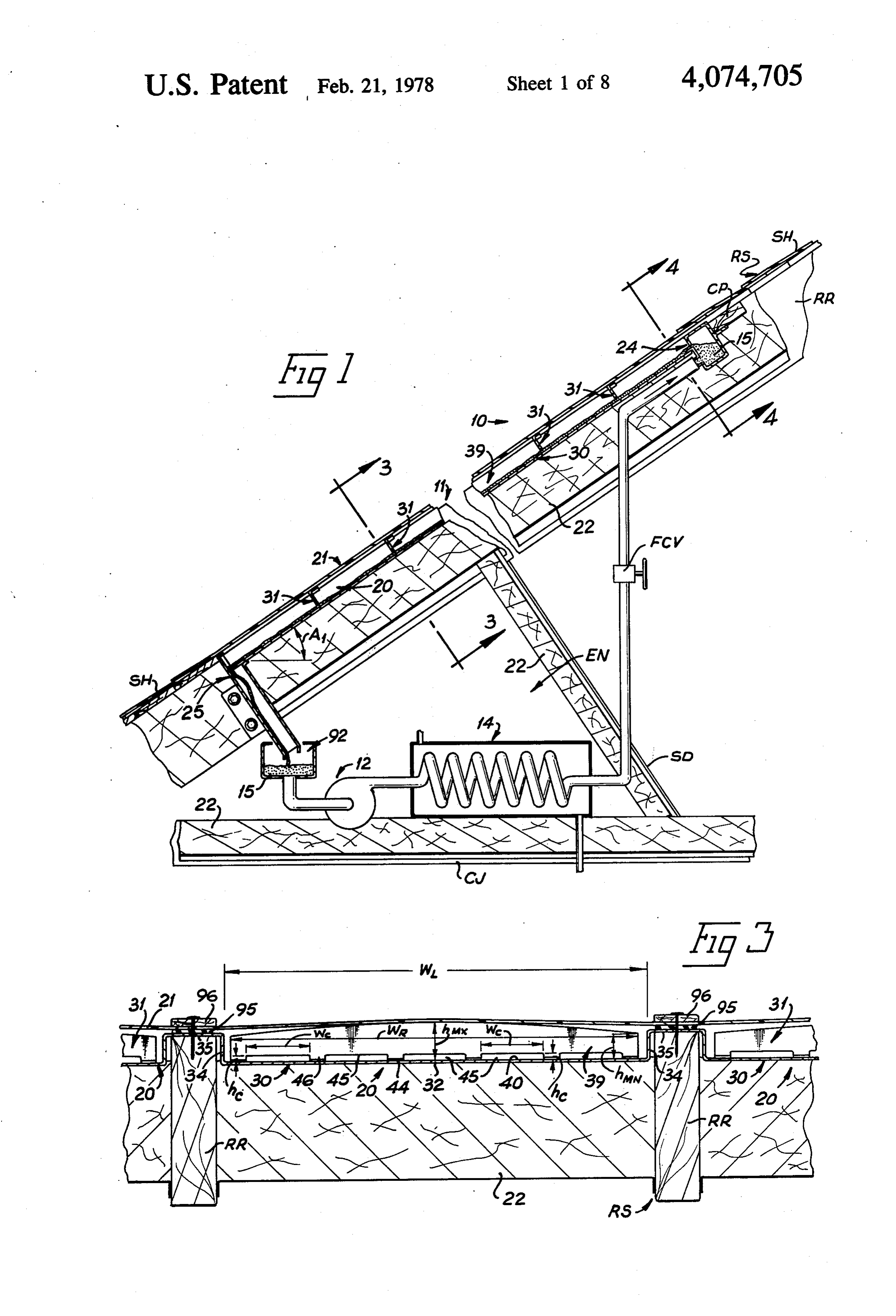
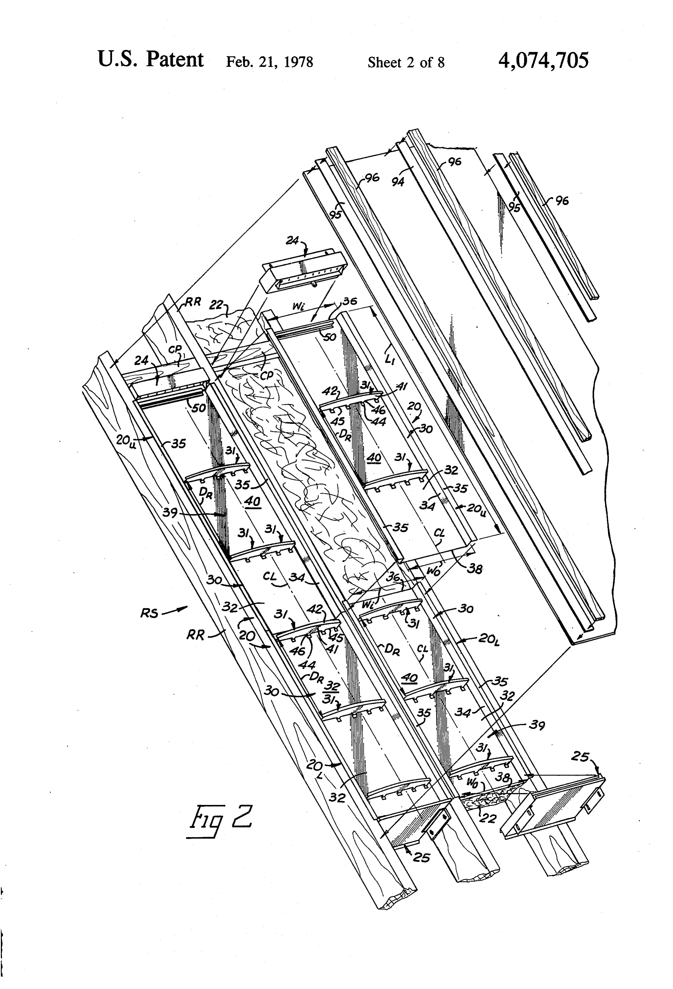
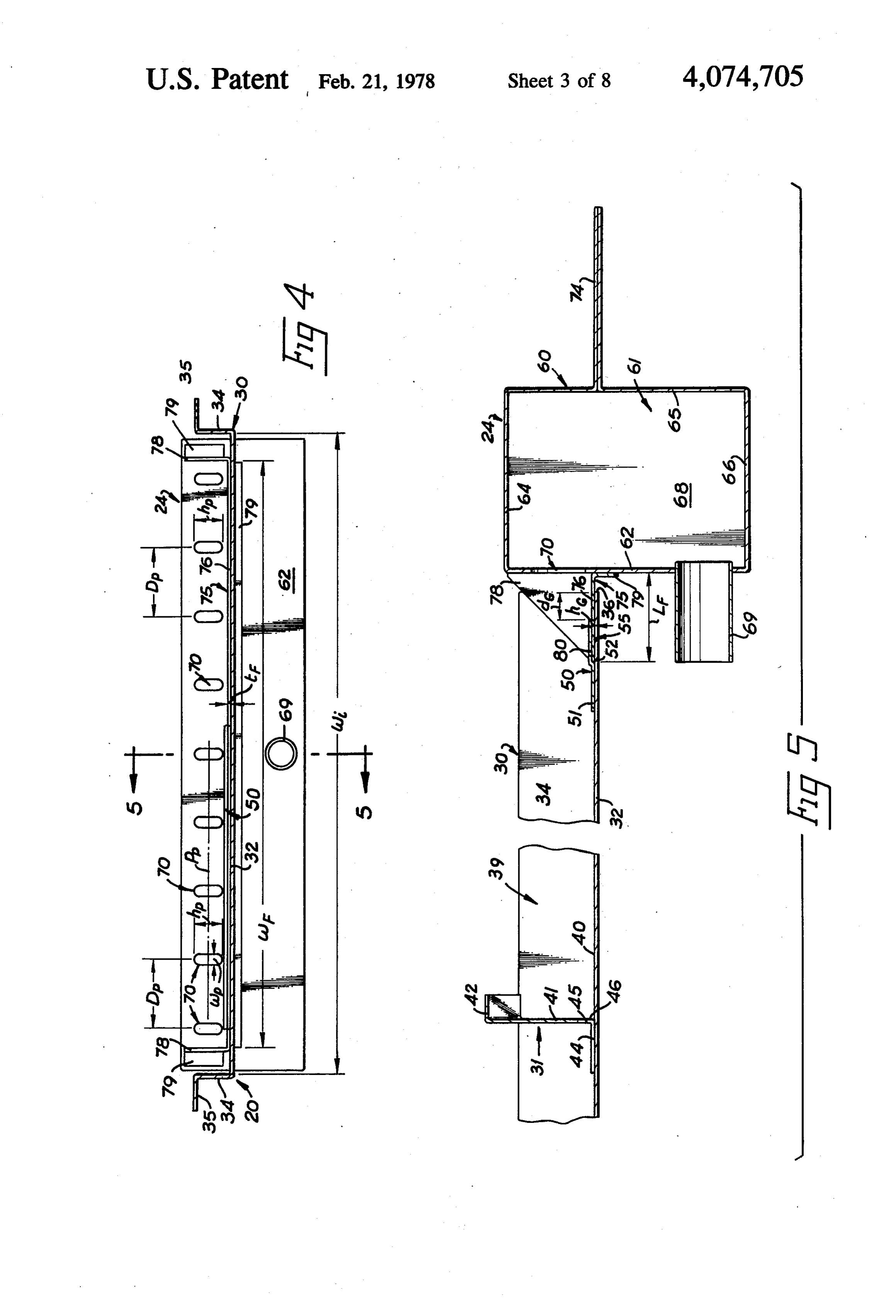
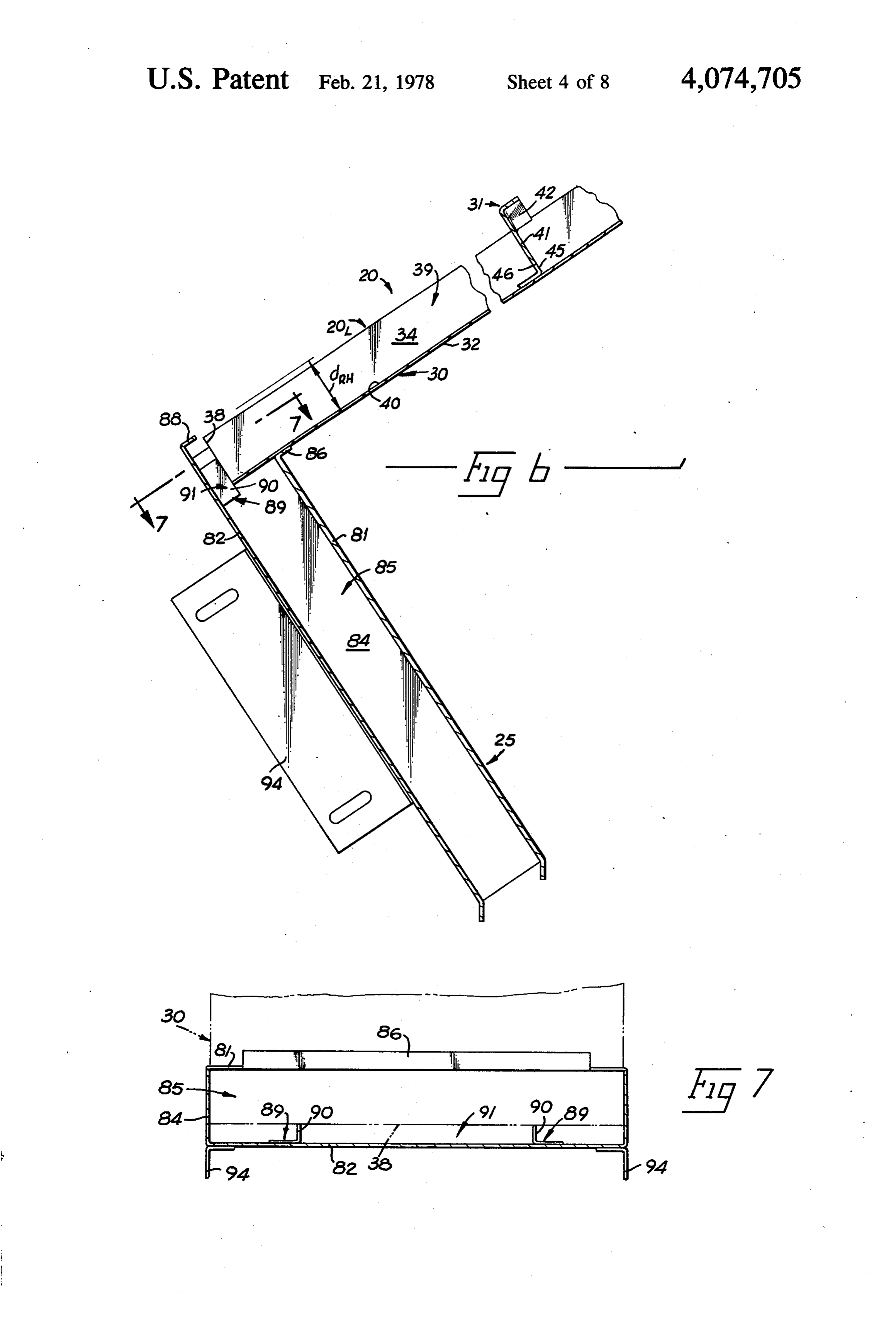
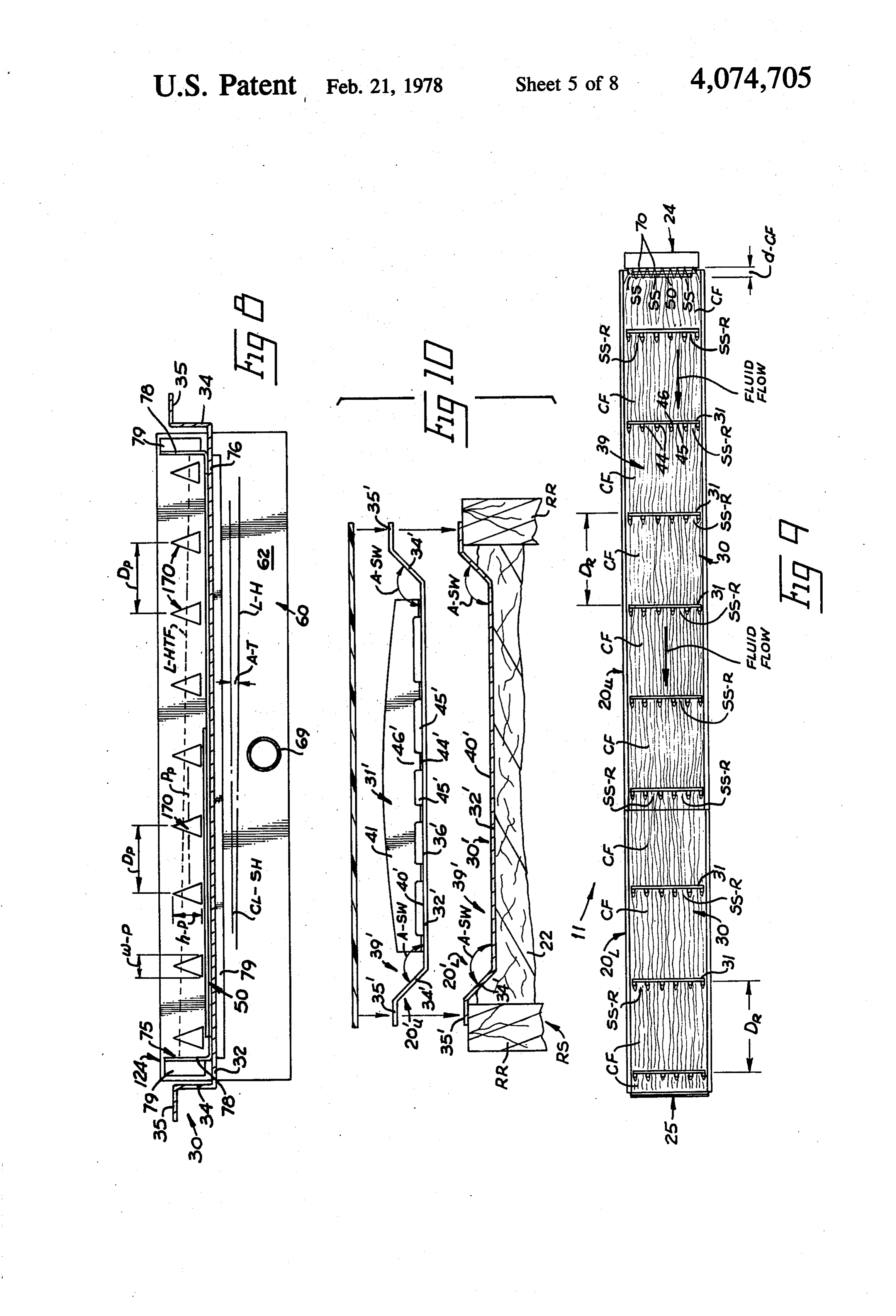
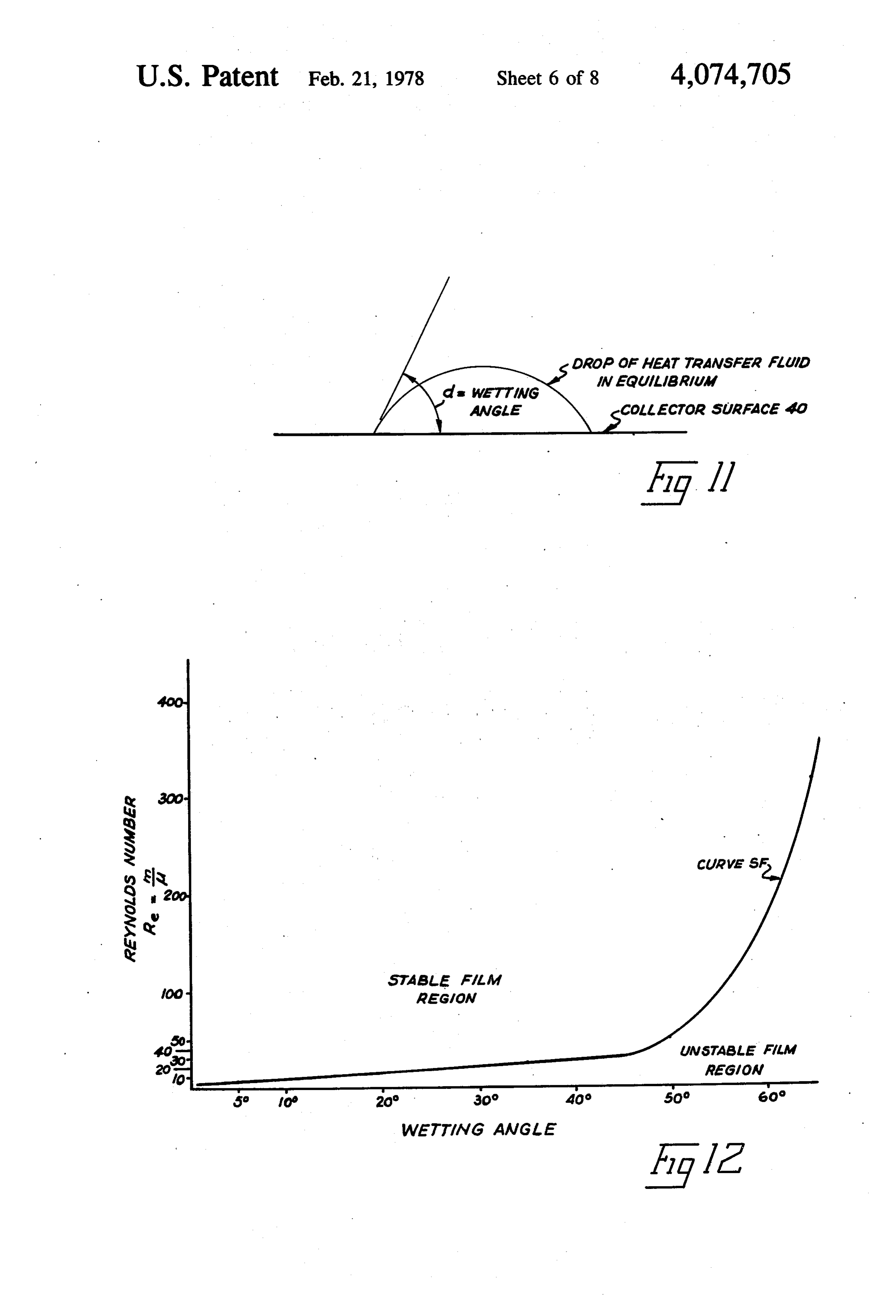
FIG. 1 is a schematic diagram illustrating one em ing pump 12. The collector 11 may include a plurality of bodiment of the invention showing the solar collector in 10 collector pans 20 as seen in FIG. 2 serially connected longitudinal cross-section; together to form a collector 11 of any desired length. FIG. 2 is an exploded perspective view of the solar Referring now to FIGS. 2, 3, 5 and 6, it will be seen collector of the invention; that each collector pan 20 includes an elongate trough FIG. 3 is an enlarged transverse cross-sectional view 30 with a plurality of transversely extending ribs 31 of the solar collector taken along line 3-3 in FIG. 1; 15 thereon. Because more than one collector pan may be FIG. 4 is an enlarged discharge side view of the sup used, the upper collector pan has been designated 20 ply header of the invention taken along line 4-4 in and the lower collector pan has been designated 20 in FIG. 1; FIG. 2 for clarity. Basically, both the upper and lower FIG. 5 is a cross-sectional view of the upper end of collector pans 20, and 20 have the same construction the invention including the supply header taken along 20 and only the upper pan 20 will be described in detail line 5-5 in FIG. 4; with like reference numbers applied to the lower pan FIG. 6 is an enlarged longitudinal cross-sectional 20.
view of the lower end of the collector of the invention; The trough 30 of each pan 20 has a centerline CL FIG. 7 is a cross-sectional view of the return header seen in FIG. 2 and a generally U-shaped transverse taken along line 7-7 in FIG. 6; 25 cross-section along its length Li best seen in FIG. 2. FIG. 8 is a view similar to FIG. 4 showing an alter Trough 30 as best seen in FIG. 3 has a generally flat nate construction for the supply header; bottom wall 32, a pair of opposed upstanding side walls FIG. 9 is a top view of the solar collector illustrating 34 integral with opposite edges of the bottom wall 32 the flow of the heat transfer fluid thereover; along the length of the trough, and a pair of opposed, FIG. 10 is an exploded transverse cross-sectional 30 outwardly extending support flanges 35 integral with view taken at the joint between modified upper and the top edges of the side walls 34 along their length. The lower collector pan assemblies; side walls 34 may be normal to bottom wall 32 and FIG. 11 is a schematic view illustrating wetting an flanges 35 are generally parallel to bottom wall 32. The gle, flanges 35 project outwardly from the side walls 34 and FIG. 12 is a graph illustrating the relationship be 35 serve to support the collector pan 20 as will become tween Reynolds Number and wetting angle to maintain more apparent.
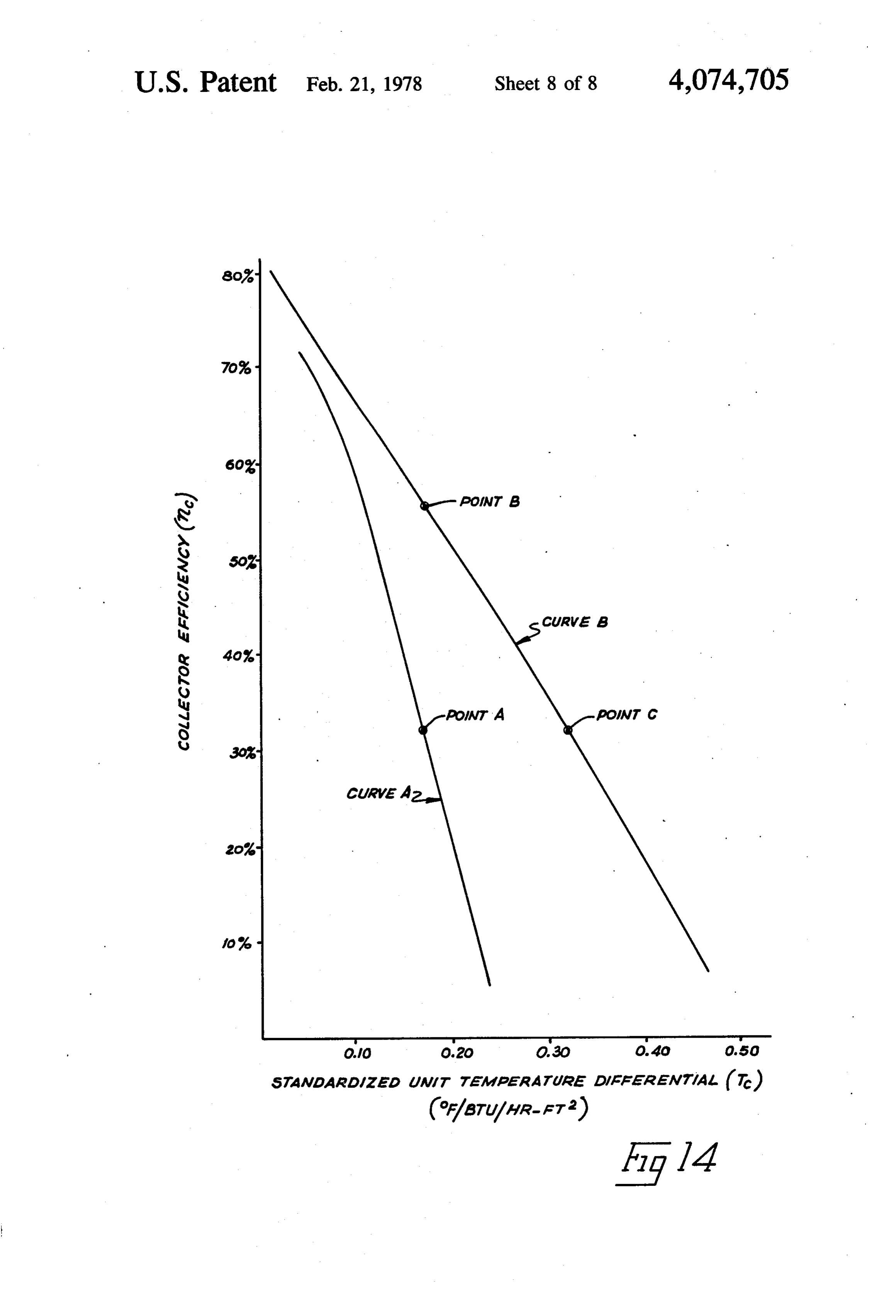
a stable heat transfer fluid film in a solar collector; The upper upstream end 36 of each trough 30 has an FIG. 13 is a graph illustrating the relationship be inside width w, between the inside surface of side walls tween thermal heat loss and vapor pressure differential 34 while the lower downstream end 38 of each trough on the heat transfer fluid; and, 30 has an outside width w, between the outside surfaces FIG. 14 is a graph comparing the collection effi of side walls 34 as best seen in FIG. 2 substantially equal ciency of the invention with the prior art. to width w so that the lower end of each trough 30 will These figures and the following detailed description fit in the upper end of another trough 30 as seen in FIG. disclose specific embodiments of the invention, how 2. This allows a plurality of the troughs 30 to fit to ever, it is to be understood that the inventive concept is 45 gether serially so that a longer collector can be fabri not limited thereto since it may be embodied in other cated using standard components as will become more forms. apparent. . .
DETAILED DESCRIPTION OF ILLUSTRATIVE The side walls 34 and bottom wall 32 of trough 30 EMBODIMENTS define an open top fluid flow channel 39 along the 50 length of trough 30. The heat transfer fluid flows over
As seen in FIG. 1, the solar collector system 10 in the bottom wall 32 within channel 39 under the force of cludes a solar collector 11, a liquid pump 12 and a heat gravity. Usually, the upper solar radiation absorbing exchanger or heat storage device 14 with a heat transfer surface 40 of bottom wall 32 is painted or plated black fluid 15 which flows from the top to the bottom of the to readily absorb almost all of the slar radiation in solar collector 11 by gravity and is returned to the top 55 pressed thereon to head the bottom wall 32. of the collector by the liquid pump 12 after passage Each collector pan 20 has a plurality of the ribs 31 through the heat exchanger 14. The solar collector 11 is mounted on the bottom wall 32 of the elongate trough usually inclined at an angle Also that it faces the sun to 30 which are oriented generally normal to the center receive solar radiation therefrom and may be incorpo line CL of the trough 30 within a prescribed distance rated into the roof structure RS of a building or sup D. seen in FIGS. 2 and 9 between each of the ribs 31. ported in a separate framework. The ribs 31 have the same construction and therefore The solar collector 11 as best seen in FIGS. 1-8 in only one rib 31 will be described in detail with like cludes generally a collector pan 20 defining a fluid flow reference numbers applied to the other ribs. Each rib 31 channel along the length thereof and typically is painted as seen in FIGS. 3 and 5 has a width w which usually or plated black on that side facing the sun to make it 65 is less than the inside width w, between the side walls 34 highly absorbent to solar radiation, one or more glass or and is centered across the width of the bottom wall 32 plastic covers 21 which close the fluid flow channel in of the trough 30. Each rib 31 has a central web 41 which pan 20 and serve to transmit the received solar radiation is oriented generally normal to the solar heat absorbing 12 surface 40 of the bottom wall 32 of the trough 30 and 64, a rear wall 65, a bottom wall 66, and a pair of end normal to the centerline CL. The upper edge of the web walls 68 which connect the walls 62 and 64-66 at oppo 41 may be arcuate as seen in FIG. 3 and is provided site ends thereof to define the reservoir 61. The lower with a support lip 42, best seen in FIG. 5, generally portion of the housing 60 is provided with a fluid inlet normal to the central web 41 to support the collector 5 tube 69, here shown as being positioned in the lower cover 21 over the fluid flow channel 39 as will become portion of the front wall 62, through which the heat apparent. The central web 41 has a minimum height transfer fluid is supplied to the reservoir 61. hiyat its opposite ends as seen in FIG.3 about equal to The heat transfer fluid is discharged from the reser the height of the side walls 34 and a maximum height voir 61 through a plurality of outlet ports 70 best seen in hat its center which is usually slightly higher than the 10 FIG. 4 in the upper portion of the front wall 62 which side walls 34 to slightly curve the collector cover 21 if communicate with the reservoir 61. The outlet ports 70 it is flexible as will become more apparent. The lower are arranged along a common path PP extending across edge of the central web 41 is provided with a plurality the width of the header 24 with the path Pebeing gener of attachment tabs 44 seen in FIGS. 3 and 5 which ally parallel to the solar radiation absorbing surface 40 extend outwardly from the central web 41 generally 15 in the trough 30 of the collector pan 20. The ports 70 normal thereto for attachment to the upper solar heat are spaced across the width of the header 24 with a absorbing surface 40 of the bottom wall 32 of trough 30 prescribed distance Detherebetween. Each of the ports by conventional means such as welding. The lower 70 has a prescribed width we and a prescribed height he edge of the central web 41 is provided with a plurality which will determine the total volume flow rate possi of cutouts 45 therethrough best seen in FIG. 3 between 20 ble from the reservoir 61. Thus, the width w and the the attachment tabs 44. The cutouts 45 have a pre height hpare selected so that the total discharge opening scribed width we and prescribed height hoto allow the area of the ports 70 is at least great enough to provide heat transfer fluid to pass under the ribs 31 around the the maximum volume flow rate for the heat transfer attachment sections 46 connecting the web 41 proper to fluid that may be required in the operation of the collec the attachment tabs 34. It will be noted that the width 25 tor system. The use of elongate ports 70 in the header 24 and number of cutouts 45 are such that the heat transfer tends to reduce the need for precise leveling of the inlet fluid can flow along over the solar heat absorbing sur header 24 to assure substantially uniform flow across face 40 on the bottom wall 32 of the trough 30 and the width of the solar radiation absorbing surface 40. through the cutouts 45 over the major portion of the This is because a change in the level of the heat transfer width of the solar radiation absorbing surface 40. The 30 fluid in the reservoir 61 across the width of the header height he of the cutouts 45 is selected to be greater than 24 generates less of an increase in flow difference be the maximum film thickness that will be encountered in tween one side of the header 24 and the other side of the the heat transfer fluid as it flows along the surface 40 of header than would be encountered if a single opening the bottom wall 32 as will become more apparent. The extending all the way across the width of the header 24 ribs 31 serve primarily to keep the solar heat absorbing 35 was used.
surface 40 on the bottom wall 32 substantially flat and to Alternatively the discharge ports from the supply support the cover 21. The ribs 31 also serve to reduce header 24 may have a generally triangular shape as convective currents in the air in the channel 39 between shown by ports 170 in FIG. 8. The rest of the header 124 is the same as header 24 and has like reference nu the cover 21 and the film of heat transfer fluid 15 flow ing down the surface 40. 40 merals applied thereto. The ports 170 are also arranged The upstream end 36 of trough 30 in upper collector along the common path PP with the prescribed distance pan 20 may be provided with a grip strip 50 seen in Detherebetween. Each port 170 tapers inwardly from FIGS. 2, 5 and 9 carried on the bottom wall 32 normal its bottom to its top with a maximum height h-Palong to centerline CL. The grip strip 50 serves to facilitate its vertical axis, and a maximum width w-P at its lower the attachment of the upper collector pan 20ty to the 45 end. The width w-P and height h-P are selected so that supply header 24 as will become more apparent. The the total discharge opening area of the ports 170 is at grip strip 50 includes an attachment flange 51 attached least great enough to provide the maximum flow rate to the solar heat absorbing surface 40 of the bottom wall for the heat transfer fluid that may be required in the 32, a central spacer section 52 integral with the attach operation of the collector system. The use of the ta ment flange 51 and generally normal to the surface 40, 50 pered ports 170 minimize the variations in fluid flow and an upper engagement lip 54 integral with the upper rate through the ports across the width of the collector edge of the spacer section 52 and extending from sec pan when the header 24 is not exactly level. This feature tion 52 opposite flange 51 over the surface 40 of the is best seen in FIG. 8 where the header 124 is shown bottom wall 32 generally parallel therewith and spaced tilted with respect to the horizontal seen as line L.-H. thereabove a prescribed heightho. The upstream end of 55 The centerline CL-SH of the supply header 124 defines lip 54 is spaced downstream of the end 36 of trough.30 an angle A-T with line L.-H. Since the heat transfer fluid a prescribed distance do. The supply header 24 then fits level L-HTF in the reservoir in header 124, seen as a within the space 55 between the connecton lip 54 and dashed line in FIG. 8, is always horizontally level, it the bottom wall 32 to connect the upstream end 36 of will cross ports 170 at different heights from their lower trough 30 to the header 34 as will become more appar 60 ends. Because the ports 170 are tapered, less of an in ent. The grip strip 50 may be replaced with a grip strip crease in flow difference between one side of the header on header 24 as will become more apparent. 124 and the other side of the header is generated than The supply header 24 best seen in FIGS. 4 and 5 would be encountered if a single opening extending all includes generally a housing 60 defining a heat transfer the way across the width of the header 124 was used. fluid reservoir 61 therein which receives the heat trans 65 Actually, the system of the invention can tolerate a fer fluid under the pressure of pump 12 for distribution considerable degree of nonuniformity in flow there in the fluid flow channel 39 in the collector pan 20. The across. The important consideration is that the mini housing 60 generally includes a front wall 62, a top wall mum flow rate be great enough to cool the surface 40 13 with an acceptable temperature gradient while the max and in alignment therewith. Thus, the downstream end imum flow rate be small enough to prevent splashing of bottom wall 32 on trough 30 abutts lips 90 as seen in waves in the flow down the surface 40. FIG. 6 to provide a discharge clearance space 91 so that A discharge ledge 75 seen in FIGS. 4 and 5 is pro the heat transfer fluid can flow out of the downstream vided on the discharge side of the front wall 62 under 5 the ports 70 to provide a connection between the header end 38 of trough 30, through passage 85 in header 25, and into a receiver 92 seen in FIG. 1 so that the heated 24 and the upstream end 36 of the trough 30 of collector fluid 15 can be pumped by pump 12 through heat ex pan 20. The discharge ledge 75 includes generally a changer 14 back to the supply header 24. Mounting bottom flange 76 with a prescribed width w greater brackets 94 are provided on opposite sides of header 25 than the distance between the outermost ports 70 and O to mount Same.
less than the distance w, between the side walls 24 of the trough 30. The flange 76 has a length Las will become The cover 21 is a relatively thin sheet of material more apparent. A pair of upturned end flanges 78 are which will transmit almost all of the solar radiant en provided at opposite ends of the bottom flange 76 and ergy incident thereon through the cover 21 into the are integral therewith. The end flanges 78 are oriented 15 channel 39 in trough 30 so that the transmitted solar generally normal to the bottom flange 76 with the bot radiation is impressed on the solar radiation absorbing tom flange 76 being parallel to the path PP of the ports surface 40 in trough 30. While a number of different 70. Appropriate mounting tabs 79 are provided along materials have this capability, a fiber glass reinforced the edges of the bottom flange 76 and the end flanges 78 polyester plastic sheet has been found quite satisfactory. for attachment to the front wall 62 of the housing 60. 20 Such sheet material is commercially available from The thickness tof the bottom flange 76 is such that the Kalwall Corporation of Manchester, New Hampshire, bottom flange 76 will just be slidably received in the and transmits about 90% of the solar energy incident on space 55 between the grip strip 50 and the solar radia it therethrough. The cover 21 is sufficiently long to tion absorbing surface 40 of the bottom wall 32 on the cover the channel 39 in trough 30 and is wider than trough 30. It will further be noted that the grip strip 50 25 channel 39. Where multiple collector pan 20 are used in is positioned the prescribed distance do downstream of parallel, the cover 21 may be made sufficiently wide to the upstream end 36 of the trough 30 so that the up span stream end 36 of the trough 30 will always extend past The more than one collector pan 20 as seen in FIG. 2. the downstream edge 80 of the bottom flange 76 on the trough 30 and21return cover is placed over the supply header 24, header 25 so that it is supported by discharge ledge 75 sufficiently to prevent leakage. This 30 the lips 42 on ribs 31 as seen in FIG. 5. The oppositeside will insure that all of the heat transfer fluid being dis edges of cover 21 are sealed with sealing gaskets 95 and tributed out of the supply header 24 will pass along the held in place by clamping strips 96 with conventional fluid flow channel 39 over the solar heat absorbing fasteners as seen in FIG. 3.
surface 40. The length LF of the bottom flange 76 is greater than the distance do so that the flange 76 will 35 It is to be understood that more than one cover 21 project into space 55 before the upper end 36 of trough may be used to cover the collector pans 20 with the 30 abutts the housing 60 of header 24. Alternatively, the covers overlying each other. When more than one grip strip 50 may be eliminated on trough 30 and an cover 21 is used, an air space is usually left between appropriate grip strip (not shown) carried by header 24 overlying covers to reduce the thermal and radiant heat to hold the upper end 36 of trough 30. A convenient 40 loss from the fluid flow channel 39. The use of these attachment flange 74 is provided on the back wall 65 of overlying covers allows the maximum available output housing 60 and extends across the width thereof. Flange temperature in the heat transfer fluid 15 to be raised 74 serves to mount header 24 as will become more ap without excessive heat loss.
parent. The troughs 30 may also be made so that they can be The return header 25 as best seen in FIGS. 6 and 7 45 overlapped while keeping their width substantially con receives the heat transfer fluid after it has flowed down stant along their lengths. Such troughs are illustrated in channel 39 under the influence of gravity and has been FIG. 10 and designated as troughs 30'. These troughs heated by the bottom wall 32 of trough 30. Header 25 30' have a generally flat bottom wall 32', a pair of op includes spaced apart front and back walls 81 and 82 posed side walls 34' integral with opposite edges of joined along opposite edges by end walls 84 to define a 50 bottom collection passage 85 therethrough with a generally tending wall 32, and a pair of opposed, outwardly ex rectilinear cross-section open at its upper and lower edges of the sideflanges support walls 55' integral with the upper 34. Unlike side walls 34 of ends. The front wall 81 terminates a prescribed distance trough 30, the side walls 34' angle di below the upper edge of back wall 82 which is bottom wall 32 at an obtuse angle outwardly from the A-SW with respect slightly greater than the total height of trough 30. The 55 to the bottom wall. Thus, when the lower upper edge of the front wall 81 is provided with an of the troughs 30' is overlapped over the end 38' of one upper end 36 outwardly extending support lip 86 normal to wall 81 and the upper edge of back wall 82 is provided with a of another trough 30, these overlapping ends will nest support lip 88 normal to wall 82 which projects over a within each other to form a liquid tight joint. Such a portion of passage 85. The header 25 is oriented so that construction allows the troughs 30' to be cut to any the walls 81 and 82 are generally normal to the bottom desired length and still be overlapped serially to form a wall 32 of trough 30 an the lower end 38 of trough 30 collector of any desired length.
projects into the passage 85 over lip 86 and under lip 88. The bottom walls 32 define the solar radiation ab To insure that the downstream end 38 of trough 30 sorbing surfaces 40' thereon and the fluid flow channel does not butt against the back wall 82 of header 25 to 65 39' therein similar to troughs 30. Ribs 31' similar to ribs restrict the flow of fluid, a pair of spacers 89 are 31 are also used with troughs 30' to complete the collec mounted on the back wall 82 of header 25, each having tor pans. The cover 21 is used to cover the troughs 30' a lip 90 oriented normal to bottom wall 32 on trough 30 similar to troughs 30.
Page 14scan →
INSTALLATION gether in parallel and that the length of each collector may be easily changed or adjusted. In parallel opera
As best seen in FIGS. 1-3, the solar collector 11 may tion, the heat transer fluid 15 is supplied to each supply be installed in the roof structure RS of the building on header 24 through a flow control valve FCV seen in which it is to be used provided the roof angle and orien- 5 FIG. 1 connected to a master supply line from the pump tation are adequate to orient the collector. Normally a 12. The flow control valves FCV are individually ad section of the roof structure is selected which generally justed to balance the flow of heat transfer fluid across faces the sun and is inclined so that the tilt angle A of the array of solar collectors 11. the collector is about equal to the latitude of the loca HEAT TRANSFER FLUID tion of the building. Each collector 11 is generally 10 mounted between the roof rafters RR best seen in FIG. The characteristics of the heat transfer fluid 15 are 2. Since the center-to-center spacing of the rafters RR is most important in the operation of a trickle-type solar generally standardized, the width of the collector 11 collector such as that of this invention. Two basic crite can likewise be standardized. ria are required, (1) that the heat transfer fluid must The maximum width between the outside surface of 15 substantially wet the entire solar radiation absorbing the side walls 34 on each trough 30 of the collector pans surface of the solar collector with a stable film and, (2) 20 is such that the side walls 34 will just fit between that the heat transfer fluid should not be vaporized in adjacent rafters RR while the support flanges 35 project the operating temperature range of the collector. out over the top edges of rafters RR to support the The ability of the heat trasfer fluid to wet the solar collector pans 20 therebetween. The width of the sup- 20 heat absorbing surface of the solar collector has been ply header 24 is such that it will just fit between the found to be a function of wetting angle a. and the dimen rafters RR at the upper end of the collector pan 20 with sionless Reynolds number Rof the fluid flowing down the discharge ledge 75 inserted under the grip strip 50. the solar heat absorbing surface. Wetting angle a is the The header 24 may be mounted on a cross-piece CP included angle defined by the edge of a drop of heat between the rafters RR through the attachment flange 25 transfer fluid with a flat horizontal surface of the same 74 on header 24 as seen in FIG. 1. The return header 25 material and finish as the solar heat absorbing surface 40 also has a width so that it will just fit between the rafters on the collector pans 20 as seen in FIG. 10. Because the RR at the lower end of collector pan 20 with the pan 20 ability of the heat trasfer fluid to wet or cover the sur projecting into the passage 85 to abutt spacers 89 in face 40 is dependent not only on the surface tension of header 25. The header 25 is mounted on rafters RR by 30 the fluid but also on the material and the finish of the brackets 94 so that the heat transfer fluid flowing down surface on which the fluid is supported, wetting angle a the collector 11 passes out of the header 25 interiorly of is the best indication of the wetting ability since it takes the roof structure.
The sealing gaskets 95 are placed over the support all of these factors into effect. Reynolds number R is defined by the equation:
flanges 35 on collector pans 20 and the cover 21 is 35 placed over the pans 20. The clamping strips 96 are fastened to the rafters RRover the cover 21 to hold it in place with the cover 21 being supported on the ribs 31 where:
in pans 20 and the gaskets 95. The upper end of the n = fluid mass flow rate per unit width down the cover 21 extends under the roof shingles SH above the 40 collector (lb/sec-ft) collector 11 and over the roof shingles SH below col L = fluid viscosity (lb/ft-sec) lector 11 as see in FIG. 1 to provide a watertight roof. The relationship between Reynolds number R and Where more length is needed in the collector 11 than wetting angle a is best illustrated in FIG. 12. The curve the length of one collector pan 20, one simply uses more SF shown in FIG. 12 is a plot of the points at which a collector pans to extend the length as seen in FIG. 2. 45 stable film of heat transfer fluid which completely cov The upper end of the lower collector pan 20 seen in ers the solar radiation absorbing surface is achieved. It FIG. 2 is simply positioned under the lower end of the will be noted that a fully stable unbroken fluid film is upper collector pan 20. The pan 20u will fit in pan 20 achieved in that area above curve SF while the fluid since the side walls 34 taper inwarly from their upper to film below curve SF is not fully stable. Since the lower ends as already explained to provide a continuous 50 amount of heat transferred from the heated solar radia fluid flow channel 39 along the entire length of pans 20. tion absorbing surface 40 to the heat transfer fluid is Thus, a collector 11 can be made of any desired length. maximized when a fully stable fluid film is present, one From a practical standpoint, collectors 11 will usually should keep the Reynolds number Rabove curve SF in be anywhere from about 8 to about 50 feet in length. FIG. 12. On the other hand, the higher the Reynolds The pans 20 will usually be about 4-8 feet in length for 55 number R, the greater is the tendency of the fluid film ease in manufacture and handling. to form waves or ripples therein that may result in the Insulation 22 is positioned under the collector pans 20 fluid splashing onto the other surfaces of the collector. as seen in FIG. 1 and attached to the rafters RR. To This also results in lower collection efficiency. To mini simplify the insulation of the fluid receiver 92, the liquid mize the formation of waves or ripples in the fluid film pump 12 and the heat exchanger 14, studs SD may be 60 flowing down the solar radiation absorbing surface, it positioned between the rafters RR and ceiling joists CJ has been found that usually the Reynolds number R. as seen in FIG. 1 inboard of the equipment. Insulation should not exceed about 100 and should be as low as 22 is then positioned between the studs SD and also possible. From FIG. 12, it will be seen that curve SF between the ceiling joists CJ if they are not already starts rising at a rapidly increasing slope when the wet insulated to define an insulated enclosure EN about the 65 ting angle a of the heat transfer fluid exceeds 50 and equipment. very quickly requires a Reynolds number R greater Another feature of this invention is that any number than 100 to achieve a fully stable fluid film. Therefore, of individual solar collectors 11 may be connected to the wetting angle a of the heat transfer fluid 15 should 15 not exceed 50 and preferably should be lower than 10. dimethyl silicone. In FIG. 14, Curve A indicates the It will further be noted that the stable fluid film criteria collection efficiency of water as the heat transfer fluid is independent of the tilt angle A. while Curve B indicates the collection efficiency of If the heat transfer fluid 15 is heated sufficient to be dimethyl silicone as the heat transfer fluid. The ordinate evaporated by the solar radiation absorbing surface 40, 5 is the collection efficiency m and the abscissa is the the evaporated fluid will then be subsequently con standardized unit temperature differential Tof the heat densed on the lower surface of the cover 21. This causes transfer fluid as it flows through the collector. The a high thermal heat loss from the solar radiation absorb collection efficiency mis defined by: ing surface 40 to cover 21 for dissapation into the atmo sphere through a heat pipe effect. The heat transfer 10 n = (Qcoll/Qsolar) X 100 fluid condensing on the back of cover 21 also partially blocks the incoming solar radiation from reaching the where solar radiation absorbing surface 40 to further reduce Qcoll = heat output of collector fluid (Btu/hr-ft2) the collection efficiency of the collector. Qsolar = Insolation = Solar radiation impressed on The parameter which controls the thermal heat loss 15 collector (Btu/hr-ft2) by evaporation and subsequent condensation on the The standardized unit temperature differential tis de cover is the difference between the heat transfer fluid fined by:
vapor pressure at the highest temperature to which the heat transfer fluid is exposed and the lowest tempera T. = (T-T)/Qsolar ture to which the heat transfer fluid is exposed as it 20 where flows down the collector. The highest temperature for T = average heat transfer fluid temperature as it the collector illustrated is that of the solar radiation absorbing surface 40 while the lowest temperature is flows over the length of the collector (F) that of the inside surface of the cover 21 which directly Because=the
Tim ambient air temperature (F) heat transfer between the solar radiation overlies the heat transfer fluid as it flows down the 25 surface 40. Forsake of simplicity the difference in vapor collector 11 shown40isand absorbing surface the heat transfer fluid 15 in the pressures will be referred to hereinafter as the vapor the average temperature of the good, the temperature Tris also surface 40. The stan pressure differential AVP of the heat transfer fluid. The dardized unit temperature differential thermal heat loss Qis by evaporation and condensation of one curve even though the receivedtallows the use solar radiation becomes significant when the vapor pressure differen 30 varies.
tial AVP of the heat trasfer fluid exceeds about 0.3 psia As seen in FIG. 14, the collection efficiency musing as seen in FIG. 13. Thus, the vapor pressure differential water as the heat transfer fluid is considerably lower AVP should be less than about 0.3 psia and preferably than that using dimethyl silicone as the heat transfer should be less than about 0.15 psia. fluid at the same value of the temperature differential T. Based on these criteria, it will be seen that the almost 35 exclusively used prior art heat transfer fluid, water, For instance, if the ambient temperature T is 50 F, does not meet the criteria set forth above. On the other the average heat transfer fluid temperature Tis 100°F hand, many mineral and synthetic fluids and oils, espe and the received solar radiation Qsolar is 300 Btu/hr-ft, cially silicone fluids, meet these criteria. These fluids the standardized unit temperature differential T would and oils may also be obtained which are desirably fire be 0.167 F/Btu/hr-ft. Referring to FIG. 14, this value resistant, non-toxic, non-corrosive and have low oxida for the temperature differential T shows that water tion characteristics. would have a collection efficiency m of only 32% at The viscosity characteristics of the heat transfer fluid Point A on Curve A while dimethyl silicone has a col 15 are also important to the successful operation of the lection efficiency of over 55% at Point B on Curve B. collector system of the invention. On the one hand, the 45 This would permit about a 42% reduction in collector viscosity of the heat transfer fluid must be sufficiently area to supply the same quantity of heat output Qcoll at high at the maximum operating temperature of the col the temperature T or temperature differential T lector system in order to maintain the Reynolds number given.
sufficiently low to prevent undesirable waves and On the other hand, the same efficiency can be splashing in the fluid film. On the other hand, the vis 50 achieved with dimethyl silicon as can be achieved with cosity of the heat transfer fluid must be sufficiently low water but at a much higher average heat transfer fluid at the coldest temperature associated with the collector temperature T. For instance, in the above example system to allow the heat transfer fluid to be pumped where the ambient temperature T is about 50 F and without undesirably high pumping losses. The silicone the insolation Qt is about 300 Btu/hr-ft, the collec fluids mentioned above are especially suited for the heat 55 tion efficiency could be maintained at about 32%, the transfer fluid because of their very uniform viscosity same as water, with the average heat transfer fluid ten temperature characteristics. It is to be understood that perature T at about 145° F as shown by Point C on any heat transfer fluid may be used which meets the Curve Busing dimethyl silicone or an increase of about above requirements as to wetting angle a. and vapor 45% in the output temperature of the heated dimethyl pressure differential AVP. Usually, the heat transfer silicone. It will further be noted that water reaches a fluid 15 will have a viscosity range of about collection cutoff value (i.e. where mast0) at a much 0.0007-0.050 lb/ft-secover the operating temperature lower value of temperature differential T than the heat range of the collector system. transfer fluid 15 of the invention. The resulting differences between the use of the prior The equipment which the solar collector is driving art heat transfer fluid, water, and a heat transfer fluid 15 65 determines the required output temperature in the heat coming within the above criteria can best be illustrated transfer fluid. In some cases, the output temperature can by reference to FIG. 14 and attached Table I. The par be relatively low thus permitting a higher percentage of ticular heat transfer fluid 15 selected for comparison is the incoming solar radiation to be collected by the di 16 methyl silicone at the same temperature as is available re-radiate a large portion of the solar radiation back out from water. Where the output temperature must be high of the collector when it is not covered by the heat trans such as is the case with absorption type refrigeration or fer fluid and thus reduce the idle temperature of surface air conditioning systems, the same efficiency as is avail 40. When the surface 40 is again covered by the solar able with water can be obtained with dimethyl silicone 5 radiation absorbing heat transfer fluid, the reflected or but at a much higher temperature. . re-radiated solar radiation will be blocked and the solar The formation of the film of heat transfer fluid 1 radiation absorbed by the heat transfer fluid. The heat which meets the above requirements is illustrated in transfer fluid may be made absorbent to solar radiation FIG. 9. The heat transfer fluid 15 is discharged in sepa- in a number of different ways. One technique that is rate streams SS from the outlet ports 80 in the supply 10 satisfactory is to mix carbon black in the fluid. header 24 onto the solar radiation absorbing surface 40 Practically, it is preferable to maintain the maximum in the upper end of the fluid flow channel 39. These temperature of the heat transfer fluid as low as possible separate streams SS rapidly spread out to become a to reduce thermal heat losses. Ideally, the heat transfer continuous film CF within a prescribed distance d-CF fluid should either absorb therein or transmit there downstream of the header 24. This distance d-CF is 15 through to surface 40 substantially all of the received usually a few inches. When the continuous film CF solar heat thereon while at the same time not thermally strikes one of the ribs 31, it is sub-divided into separate radiate the heat therefrom in order to maximize the streams SS-R by the attachment sections 46 in the web retained heat in the heat transfer fluid.
Table i
Heat transfer fluid: water dimethyl silicone
Flow rate R;
Tile angle (A):
iscosityage
Vapor pressure differential (Tc): 0.77 psia at 100 F Below 0.01 psia at 100 F Reynolds number (R): 146 at 100 F 12 at 100
4 and tabs 44 of rib 31 so that all of the heat transfer fluid 15 passes through the cutouts 45 in the rib 31. The separate streams SS-R downstream of rib 31 again rap- We claim:
idly spread out to reform the continuous film CF as the 30 1. A solar collector system for solar radiation com fluid continues to flow down the collector. Thus, the prising:
solar radiation absorbing surface 40 is virtually com- a collector assembly defining a fluid flow, channel pletely covered by the film of heat transfer fluid 15. therein inclined with respect to the horizontal at a Because the heat generated at surface 40 by the ab- prescribed inclination angle and further defining a sorbed solar radiation is readily transferred to the heat 35 solar radiation absorbing surface along the bottom transfer fluid 15 flowing thereover, the temperature of of said fluid flow channel onto which the solar the fluid is usually substantially equal to the temperature radiation is impressed, said collector assembly fur of surface 40. Under usual operating temperatures, the ther including a cover forming one side of said temperature of the heat transfer fluid 15 as it exits the fluid flow channel and capable of transmitting solar collector may range from about 70 to about 170 F 40 radiation therethrough into said fluid flow channel; depending on the temperature required to drive the a heat transfer fluid for flowing down said fluid flow equipment associated with the collector system. To channel over said solar radiation absorbing surface maintain good efficiency of operation the temperature under said cover, said heat transfer fluid having a differential between the inlet and outlet temperatures of fluid vapor pressure differential between the maxi the heat transfer fluid may vary from about 10 to about 45 mum and minimum temperatures to which said 50 F. heat transfer fluid is exposed during flow down Where the solar radiation is absorbed by the surface said fluid flow channel of less than about 0.3 psia; 40 and then transferred to the heat transfer fluid 15 from and, surface 40, the film of heat transfer fluid flowing down means for supplying said heat transfer fluid to the surface 40 should be relativly thin in order that the film 50 upper end of said channel for the flow of said heat blocks very little of the solar energy from reaching the transfer fluid along said channel over said solar surface 40. This film thickness is less than about 0.25 radiation absorbing surface under the force of inch and typically is about 0.025 inch. gravity to heat said transfer fluid. On the other hand, the heat transfer fluid itself may 2. The solar collector system of claim 1 wherein said be capable of absorbing the solar radiation to heat the 55 heat transfer fluid further defines a wetting angle with fluid directly. Where the fluid absorbs the solar radia respect to said solar radiation absorbing surface of less tion directly, it would not be necessary to make the than about 50'.
surface 40 highly absorbent to solar radiation. This 3. The solar collector system of claim 2 wherein said feature may be desirable, especially where the collector heat transfer fluid defines a wetting angle with respect has idle times in which the heat transfer fluid is not to said solar radiation absorbing surface of no greater being pumped onto the surface 40 and the surface 40 is than about 10 and wherein said heat transfer fluid has a being exposed to solar radiation without being cooled fluid vapor pressure differential at the temperatures to by the heat transfer fluid. An uncooled, dark solar radia which said fluid is exposed in the system of no greater tion absorbing surface 40 may reach sufficiently high than about 0.15 psia.
temperatures to undesirably degrade collector compo 65 4. The solar collector system of claim 3 wherein said nents since temperatures in excess of 250 F can be heat transfer fluid is a silicone fluid. reached. By using a solar radiation absorbing heat trans 5. The solar collector system of claim 4 wherein said fer fluid, the surface 40 may be left bright to reflect or heat transfer fluid is dimethyl silicone.
Page 17scan →
6. The solar collector system of claim 3 wherein said 10. The method of claim 9 wherein the heat transfer collector assembly includes a plurality of collector pans; fluid supplied in step (b) is further selected to have a each of said collector pans having an upper end and a wetting angle with respect to the solar radiation absorb lower end, and comprising a generally flat bottom wall ing surface of no greater than about 50. and a pair of opposed side walls along opposite sides of 5 11. The method of claim 10 wherein step (b) further said bottom wall to define a portion of said fluid flow includes supplying the heat transfer fluid to the fluid channel therebetween extending along the length of flow channel so that the generated Reynolds number said collector pan; and each of said collector pans hav does not exceed 100.
ing a transverse cross-sectional shape so that the lower 12. The method of claim 9 wherein the heat transfer end of said one of said collector pans will nest in the O fluid supplied in step (b) is further selected to have a upper end of another of said collector pans in order for vapor pressure differential at the temperatures to which the lower end of said bottom wall of said one of said the fluid is exposed in the system of no greater than collector pans to overlap the upper end of said bottom about 0.15 psia.
wall of said another of said collector-pans to form a 13. The method of claim 12 wherein the heat transfer fluid tight connection between said collector pans when 15 fluid supplied in step (b) is further selected to have a said one of said collector pans is generally higher with wetting angle with respect to the solar radiation absorb respect to the horizontal than said another of said col ing surface of no greater than about 10. lector pans with said collector pans serially connected 14. The method of claim 9 wherein step (b) further and forming said fluid flow channel substantially as long 20 includes supplying the heat transfer fluid to the upper as the total length of said collector pans. end of the fluid flow channel at a sufficient rate to pro 7. The solar collector system of claim 1 wherein the duce a generated Reynolds number therein larger than the stable film Reynolds number required to produce a heat transfer fluid has a fluid vapor pressure differential stable film of the heat transfer fluid on the solar radia at the temperatures to which said fluid is exposed in the tion absorbing system of no greater than about 0.15 psia. surface substantially covering the solar 25 radiation absorbing surface across its width.
8. The solar collector system of claim 1 wherein said 15. A solar collector system for solar radiation com collector assembly includes a plurality of collector pans; prising:
each of said collector pans having an upper end and a a collector assembly defining a fluid flow channel lower end, and comprising a generally flat bottom wall therein inclined with respect to the horizontal at a and a pair of opposed side walls along opposite sides of 30 prescribed inclination angle and further defining a said bottom wall to define a portion of said fluid flow substantially flat, reflective channel bottom surface channel therebetween extending along the length of along the bottom of said flow channel, said collec said collector pan; and each of said collector pans hav tor assembly further including a cover extending ing a transverse cross-sectional shape so that the lower along and closing the top of said fluid flow channel, end of said one of said collector pans will nest in the 35 said cover transmitting solar radiation to which upper end of another of said collector pans in order for said cover is exposed therethrough into said fluid the lower end of said bottom wall of said one of said flow channel toward said reflective channel bot collector pans to overlap the upper end of said bottom tom surface, said channel bottom surface reflecting wall of said another of said collector pans to form a fluid most of the solar radiation transmitted through said tight connection between said collector pans when said cover back through said cover and out of said fluid one of said collector pans is generally higher with re flow channel when the solar radiation is impressed spect to the horizontal than said another of said collec directly on said channel bottom surface; tor pans with said collector pans serially connected and a heat transfer fluid for flowing down said fluid flow forming said fluid flow channel substantially as long as channel over said channel bottom surface under the total length of said collector pans. 45 said cover, said heat transfer fluid directly absorb 9. A method of operating a solar collector system for ing the solar radiation impressed thereon to di solar radiation where the collector system defines a rectly heat said heat transfer fluid while substan fluid flow channel therein with a solar radiation absorb tially preventing transmission of the solar radiation ing surface along the bottom of the fluid flow channel therethrough; and, and with the top of the fluid flow channel formed by a 50 means for selectively supplying said heat transfer cover which transmits the solar radiation therethrough fluid to the upper end of said fluid flow channel for onto the solar absorbing surface comprising the steps of: the flow of said heat transfer fluid along said fluid a. positioning the fluid flow channel so that the solar flow channel over said channel bottom surface radiation absorbing surface defines a prescribed under the force of gravity while covering said inclination angle with respect to the horizontal and 55 channel bottom surface so that the solar radiation the solar radiation absorbing surface is exposed to transmitted through said cover will be impressed the solar radiation; and, directly on the surface of said heat transfer fluid supplying heat transfer fluid to the upper end of the when said heat transfer fluid cover said channel fluid flow channel so that the heat transfer fluid bottom surface for directly heating said heat trans will flow along the solar radiation absorbing sur 60 fer fluid without transmission of the solar radiation face within the fluid flow channel under the force to said channel bottom surface and so that the solar of gravity and the solar radiation absorbing surface radiation will be impressed directly on said reflec will heat the heat transfer fluid, the heat transfer tive bottom surface and reflected back through said fluid having been selected to have a vapor pressure cover when said heat transfer fluid is not covering differential between the maximum and minimum 65 said channel bottom surface to prevent overheating temperatures to which said heat transfer fluid is of said channel bottom surface. exposed during flow down said fluid flow channel 16. A solar collector system for solar radiation com of no greater than about 0.3 psia. prising:
Page 18scan →
a collector assembly defining a fluid flow channel said bottom walls of said collector troughs under therein inclined with respect to the horizontal at a the influence of gravity to be heated by the solar prescribed inclination angle and further defining a radiation transmitted through said cover, said fluid channel bottom surface along the bottom of said supply means including a fluid supply header defin flow channel, said channel bottom surface reflect ing a fluid reservoir therein and a plurality of dis ing a prescribed portion of the solar radiation im charge ports from said fluid reservoir to discharge pressed thereon when said heat transfer fluid is not said heat transfer fluid carried in said fluid reser flowing thereover to prevent overheating of said voir therefrom through said discharge ports in a channel bottom surface; and, plurality of individual and separate streams into heat transfer fluid flowing down said fluid flow 10 said fluid flow channel in said collector pan assem channel over said channel bottom surface under bly at spaced apart positions across the width of the force of gravity so that the solar radiation is said fluid flow channel; and, impressed thereon, said heat transfer fluid directly fluid return means for receiving said heat transfer absorbing the solar radiation impressed thereon to fluid from said fluid flow channel in said collector directly heat said heat transfer fluid and having a 15 trough at a point downstream of the upper end of fluid vapor pressure differential between the maxi said collector trough for recirculation of the fluid. mum and minimum temperatures to which said 20. The modular solar collector construction of claim heat transfer fluid is exposed during flow down 19 wherein said discharge ports defined in said header said fluid flow channel of less than about 0.3 psia. are vertically elongated and define a substantially con 17. The solar collector system of claim 16 wherein 20 stant cross-sectional width along the height thereof to said heat transfer fluid further defines a wetting angle minimize the variation in the amount of said heat trans with respect to said channel bottom surface of less than fer fluid discharged therefrom into said fluid flow chan about 50. nel due to said header being unlevel. 18. The solar collector system of claim 16 wherein 21. The modular solar collector construction of claim said heat transfer fluid includes carbon black particles. 25 19 wherein each of said discharge ports defined in said 19. A modular solar collector construction for use in header is vertically elongated and has a generally de collecting solar energy and adapted to be supported creasing cross-sectional width from its lower end to its between adjacent rafters in the roof structure of a build upper end to minimize the variation in the amount of ing comprising: said heat transfer fluid discharged therethrough due to a collector pan assembly adapted to be supported 30 said header being unlevel.
between adjacent rafters of the roof structure, said 22. A modular solar collector construction for use in collector pan assembly including at least two col collecting solar energy and adapted to be supported lector troughs, each of said collector troughs hav between adjacent rafters in the roof structure of a build ing an upper end and a lower end, and comprising ing comprising:
a generally flat bottom wall and a pair of opposed 35 a collector pan assembly adapted to be supported side walls along opposite sides of said flat bottom between adjacent rafters of the roof structure, said wall, said bottom wall and said side walls defining collector pan assembly including at least two col an open top fluid flow channel along the length of lector troughs, each of said collector troughs hav each of said collector troughs, the lower end of ing an upper end and a lower end, and comprising each of said collector troughs having a first pre 40 a generally flat bottom wall and a pair of opposed scribed interior shape and size and the upper end of side walls along opposite sides of said flat bottom each of said collector troughs having a second wall, said bottom wall and said side walls defining prescribed exterior shape and size complimentary an open top fluid flow channel along the length of to said first prescribed shape and size of the lower each of said collector troughs, the lower end of end of said collector trough so that the lower end 45 each of said collector troughs having a first pre of said one of said troughs will nest in the upper scribed interior shape and size and the upper end of end of said other of said troughs in order for the each of said collector troughs having a second lower end of said bottom wall of said one of said prescribed exterior shape and size complimentary troughs to overlap the upper end of said bottom to said first prescribed shape and size of the lower wall of said other of said troughs to form a fluid 50 end of said collector trough so that the lower end tight connection between said troughs when said of said one of said troughs will nest in the upper one of said troughs is generally higher than said end of said other of said troughs in order for the other of said troughs with respect to the horizontal lower end of said bottom wall of said one of said with said troughs serially connected and forming troughs to overlap the upper end of said bottom said collection pan assembly with a common fluid 55 wall of said other of said troughs to form a fluid flow channel substantially as long as the total tight connection between said troughs when said length of said collector troughs; one of said troughs is generally higher than said at least one cover extending between said side walls other of said troughs with respect to the horizontal of said collector trough to close the open top of the with said troughs serially connected and forming common fluid flow channel, said cover capable of 60 said collection pan assembly with a common fluid transmitting solar radiation therethrough into the flow channel substantially as long as the total common fluid flow channel; length of said collector troughs, said collector pan a heat transfer fluid; assembly further including rib means for maintain fluid supply means for introducing said heat transfer ing said generally flat bottom wall of said collector fluid into the common fluid flow channel at the 65 troughs in a substantially flat plane; upper higher end of said collector trough assembly at least one cover extending between said side walls so that said heat transfer fluid flows in the common of said collector trough to close the open top of the fluid flow channel along the combined lengths of common fluid flow channel, said cover capable of 19 transmitting solar radiation therethrough into the fluid supply means for introducing said heat transfer common fluid flow channel; fluid into the common fluid flow channel at the a heat transfer fluid; upper higher end of said collector trough assembly fluid supply means for introducing said heat transfer so that said heat transfer fluid flows in the common fluid into the common fluid flow channel at the 5 fluid flow channel along the combined lengths of upper higher end of said collector trough assembly said bottom walls of said collector troughs under so that said heat transfer fluid flows in the common the influence of gravity to be heated by the solar fluid flow channel along the combined lengths of radiation transmitted through said cover; and, said bottom walls of said collector troughs under fluid return means for receiving said heat transfer the influence of gravity to be heated by the solar 10 fluid from said fluid flow channel in said collector radiation transmitted through said cover; and trough at a point downstrean of the upper end of fluid return means for receiving said heat transfer said collector trough for recirculation of the fluid. fluid from said fluid flow channel in said collector 24. A solar collector system for solar radiation com trough at a point downstream of the upper end of prising said collector trough for recirculation of the fluid. 15 23. A modular solar collector construction for use in a collector assembly defining a fluid flow channel collecting solar energy and adapted to be supported therein inclined with respect to the horizontal at a prescribed inclination angle and further defining a between adjacent rafters in the roof structure of a build bottom surface along the bottom of said fluid flow ing comprising: channel onto which the solar radiation is im a heat transfer fluid; 20 pressed;
a collector pan assembly adapted to be supported a heat transfer fluid for flowing down said fluid flow between adjacent rafters of the roof structure, said channel over said channel bottom surface under collector pan assembly including at least two col the influence of gravity to be heated by the solar lector troughs, each of said collector troughs hav radiation;
ing an upper end and a lower end, and comprising 25 a fluid supply header defining a fluid reservoir therein a generally flat bottom wall and a pair of opposed and a plurality of discharge ports from said fluid side walls along opposite sides of said flat bottom reservoir to discharge said heat transfer fluid car wall, said bottom wall and said side walls defining ried in said fluid reservoir therefrom through said an open top fluid channel along the length of each discharge ports in a plurality of individual and of said collector troughs, the lower end of each of 30 separate streams into said fluid flow channel in said said collector troughs having a first prescribed collector assembly at spaced apart positions across interior shape and size and the upper end of each of the width of said fluid flow channel, each of said said collector troughs having a second prescribed discharge ports being vertically elongated and hav exterior shape and size complimentary to said first ing a substantially constant cross-sectional width prescribed shape and size of the lower end of said 35 along the height thereof to minimize the variation collector trough so that the lower end of said one in the amount of said heat transfer fluid discharged of said troughs will nest in the upper end of said therefrom into said fluid flow channel due to said other of said troughs in order for the lower end of header being unlevel; and, said bottom wall of said one of said troughs to supply means for supplying said heat transfer fluid to overlap the upper end of said bottom wall of said 40 said fluid reservoir in said supply header to raise other of said troughs to form a fluid tight connec the level of said heat transfer fluid in said reservoir tion between said troughs when said one of said sufficiently to cause said heat transfer fluid to flow troughs is generally higher than said other of said from said discharge ports in said supply header. troughs with respect to the horizontal with said troughs serially connected and forming said collec- 45 25. A solar collector system for solar radiation com tion pan assembly with a common fluid flow chan- prising:
nel substantially as long as the total length of said a collector assembly defining a fluid flow channel collector troughs, said collector pan assembly fur therein inclined with respect to the horizontal at a ther including a plurality of reinforcing ribs prescribed inclination angle and further defining a mounted on said bottom wall of said collector 50 bottom surface along the bottom of said fluid flow trough within said fluid flow channel and arranged channel onto which the solar radiation is im generally normal to the flow of said heat transfer pressed;
fluid down said bottom wall of said collector a heat transfer fluid for flowing down said fluid flow trough, each of said reinforcing ribs attached to channel over said channel bottom surface under said bottom wall at a plurality of spaced apart posi- 55 the influence of gravity to be heated by the solar tions across the width of said bottom wall to main radiation;
tain said bottom wall in a generally flat plane and a fluid supply header defining a fluid reservoir therein each of said ribs further defining a plurality of and a plurality of discharge ports from said fluid cutouts therein between said positions at which reservoir to discharge said heat transfer fluid car said rib is attached to said bottom wall for said heat 60 ried in said fluid reservoir therefrom through said transfer fluid to flow through said cutouts as said discharge ports in a plurality of individual and heat transfer fluid flows down said bottom wall of separate streams into said fluid flow channel in said said collector pan assembly; collector assembly at spaced apart positions across at least one cover extending between said side walls the width of said fluid flow channel, each of said of said collector trough to close the open top of the 65 discharge ports defined in said header being verti common fluid flow channel, said cover capable of cally elongated and having a generally decreasing transmitting solar radiation therethrough into the cross-sectional width from its lower end to its common fluid flow channel; upper end to minimize the variation in the amount 20 of said heat transfer fluid discharged therethrough the solar radiation absorbing surface is exposed to due to said header being unlevel; and, the solar radiation; and, supply means for supplying said heat transfer fluid to b. supplying heat transfer fluid to the upper end of the said fluid reservoir in said supply header to raise fluid flow channel so that the heat transfer fluid the level of said heat transfer fluid in said reservoir 5 will flow along the solar radiation absorbing sur sufficiently to cause said heat transfer fluid to flow face within the fluid flow channel under the force from said discharge ports in said supply header. of gravity and the solar radiation absorbing surface 26. A method of operating a solar collector system will heat the heat transfer fluid, the heat transfer for solar radiation where the collector system defines a 10 fluid having been selected to define a wetting angle fluid flow channel therein with a solar radiation absorb ing surface along the bottom of the fluid flow channel with respect to said solar radiation absorbing sur and with the top of the fluid flow channel formed by a face of less than about 50. cover which transmits the solar radiation therethrough 27. The method of claim 26 wherein the heat transfer onto the solar absorbing surface comprising the steps of: fluid supplied in step (b) is further selected to define a a. positioning the fluid flow channel so that the solar 15 wetting angle with respect to the solar radiation absorb radiation absorbing surface defines a prescribed ing surface of less than about 10. inclination angle with respect to the horizontal and
Provenance
- Collection
- Patents citing this work
- Pages
- 20
- Method
- pdftotext (the PDF's own text layer) + pdftoppm 300dpi page scans
- Patent office record
- patents.google.com →
- Source
- Google Patents citing-documents table
- Assignee
- Scientific-Atlanta, Inc.
- Published
- 1978-02-21
- Transcribed from
- patentimages.storage.googleapis.com →