

patent · US4290412A
Solar collector and process for its operation
22 September 1981
Text
Page 1bibliographic recordscan →
United States Patent (19.
Krauss
54). SOLAR COLLECTOR AND PROCESS FOR
ETS OPERATION
75 Inventor: Ralf Krauss, Palma de Mallorca,
Spain (73) Assignee: Walter Steinricke, Cologne, Fed.
Rep. of Germany
Foreign Application Priority Data
Oct. 6, 1978 DE Fed. Rep. of Germany ....... 2825509
52 U.S. Cl. .................................... 126/419, 126/445;
1,946,184 2/1934 Abbot .................................. 126/424
2,595,905 5/1952 Telkes. ... 126/419 3,174,915 3/1965 Golin ... ... 126/444 3,270,802 9/1966 Lindberg. ... 165/135 3,675,023 7/1972 Kunke et al. ... 126/419 3,860,055 1/1975 Wild ............. ... 126/419 3,916,871 1 1/1975 Estes et al. ... 126/444 4,016,861 4/1977 Taylor ................................. 126/449
4,038,965 8/1977 Lyon ................................... 126/446 4,061,132 12/1977 Ashton et al. ... ... 26/49 4,069,811 1/1978 Tabor ............... ... 126/446 4,078,548 3/1978 Kapany ... ... 126/449 4,088, 119 5/1978 O’Hanlon ............. ... 126/419 4,142,509 3/1979 Hermann et al. ... ... 26/419 4,153,037 5/1979 Isaacson ............... ... 126/449 4,154,222 5/1979 Yu ............ ... 126/449 4,177,795 12/1979 Schultz..... ... 126/419 4,185,616 1/1980 Johnson ....... ... 126/444 4,191,165 3/1980 Faudarole .... ... 126/445 4,203,425 5/1980 Clark ................................... 126/445 Primary Examiner-Daniel J. O'Connor
Attorney, Agent, or Firm-Neil F. Markva
The invention relates to a solar collector assembly com prising a hollow housing body that is at least partially transparent. An absorber means is contained in the housing and a vacuum pump means is connected to the housing. A particular process of operating the solar collector assembly also forms a part of this invention. Solar collector assemblies are used for converting sun energy into other forms of energy such as heat used to
prepare hot water or heat for energy production. Many attempts have been made to design solar collectors having a compact structural shape and satisfactory effi ciency to render them suitable as an energy source in dwelling houses. However, such a solar collector has not yet been attained.
31 Claims, 11 Drawing Figures
Drawings
Page 2drawing sheetscan →
Page 3drawing sheetscan →
Page 4drawing sheetscan →
Page 5drawing sheetscan →
Page 6drawing sheetscan →
Page 7scan →
in obtaining a greater efficiency of solar collector as
SOLAR COLLECTOR AND PROCESS FORTS semblies through the control of flow conditions of the (OPERATION fluid medium traveling through the absorber.
The solar collector assembly of the present invention
BACKGROUND OF THE INVENTION 5 comprises a hollow housing at least partially transpar Known solar collector assemblies include a box-type ent to solar rays. Absorber means are disposed in the bottom portion made of sheet metal and having an housing to receive the solar rays. Vacuum pump means upper aperture closed by a glass plate. An absorber is are connected to the housing to evacuate the inside of disposed in the sheet metal housing. An insulating mate O the housing. Means are provided for controlling the rial such as foamed styrene, glass wool or the like is amount of vacuum in the housing in correlation with located between the absorber and the bottom of the prevailing ambient atmospheric conditions. A particular sheet metal housing. Such collectors are referred to as feature of the invention provides for the controlling mono-cover single collectors. These prior art collectors means to automatically adjust the vacuum within the are not well suited for dwelling houses because of the 15 housing in response to changes in the prevailing ambi considerable height resulting from the inclusion of the ent atmospheric conditions. Various features of the insulating packages required to prevent heat loss in a invention are disclosed herein as effective portions of downward direction. It is not possible to reduce the the solar collector assembly.
height of the prior art structure without sacrificing the The process according to the invention herein is for insulating effect. Furthermore, this type of collector has 20 operating a solar collector including a hollow housing a relatively large weight constituting a further disad containing an absorber with the housing being con vantage. Moreover, the high edge of the box-type sheet nected to a vacuum pump. The process comprises the metal housing throws shadows over a large part of the steps of adjusting the amount of vacuum in the housing absorber inside the housing. Thus, the efficiency of the up to its complete cancellation. The adjusting step is absorber is reduced and the output of the collector is 25 maintained in correlation with prevailing ambient atmo insufficient when an angular incidence of the sun rays spheric conditions. The adjusting of the vacuum is occurs to produce these shadows. With the prior art collectors, the sun energy is effectively converted into therefor effective to control the efficiency of the func heat only when there is a relatively vertical incidence of of the solarabsorber tion of the disposed within the hollow housing collector.
sun radiation. Without insulation on the upper side of the collector, there is a further restrictive effect upon 30 BRIEF DESCRIPTION OF DRAWINGS the efficiency and output of the prior art solar collector Other objects of this invention will appear in the assemblies.
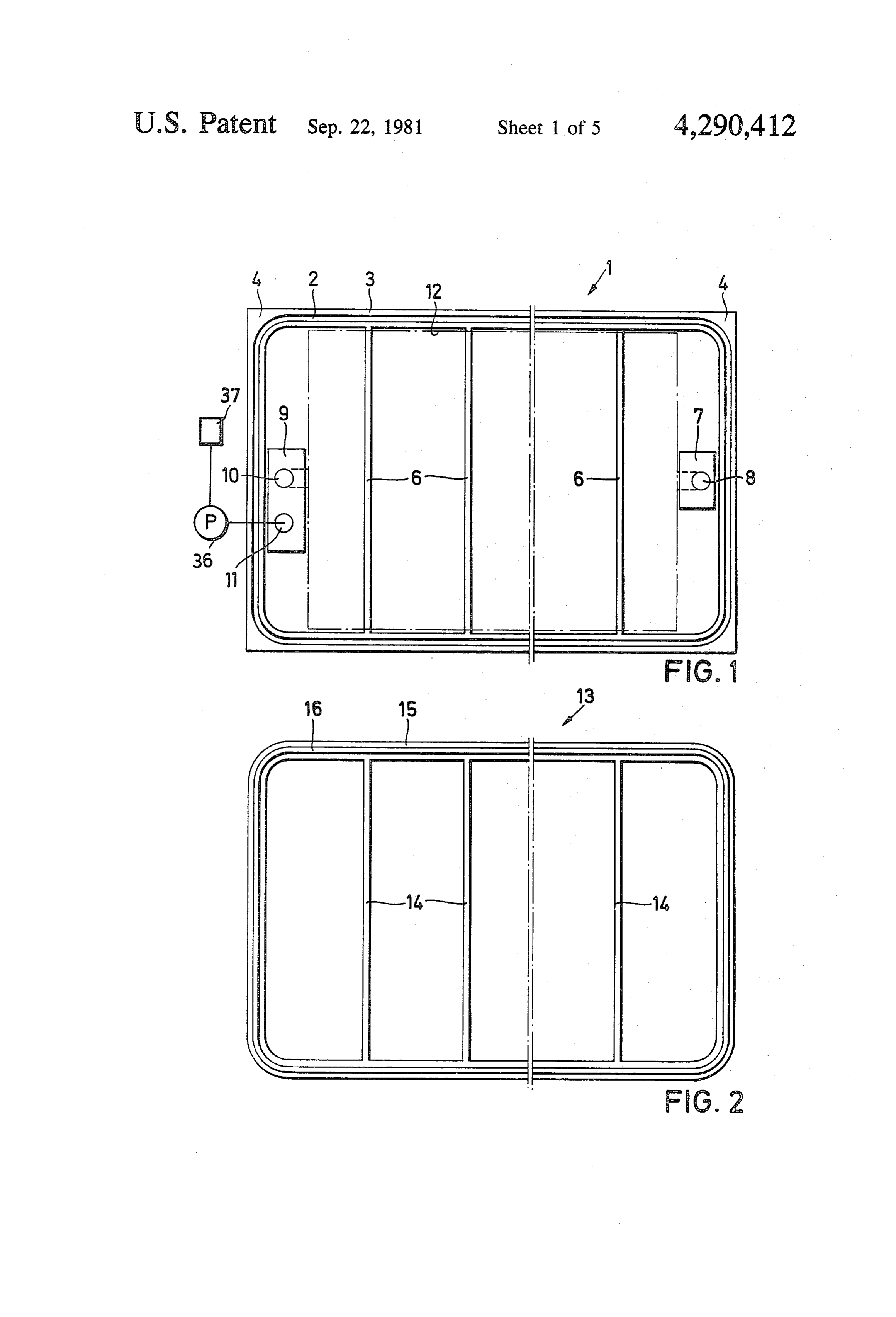
The known double cover solar collector is identical following description and appended claims, reference to the mono-cover single collector with respect to the being made to the accompanying drawings forming a box-type sheet metal housing and the required thick 35 part designateof the specification wherein like reference charac insulating package. In this collector, however, two tersFIG. 1 is a corresponding parts in the several views.
plan view of the cup-shaped bottom por glass covers are superimposed in spaced relationship tion of a solar collector made in accordance with this with respect to each other forming an air cushion be tween them. This configuration reduces the amount of invention;
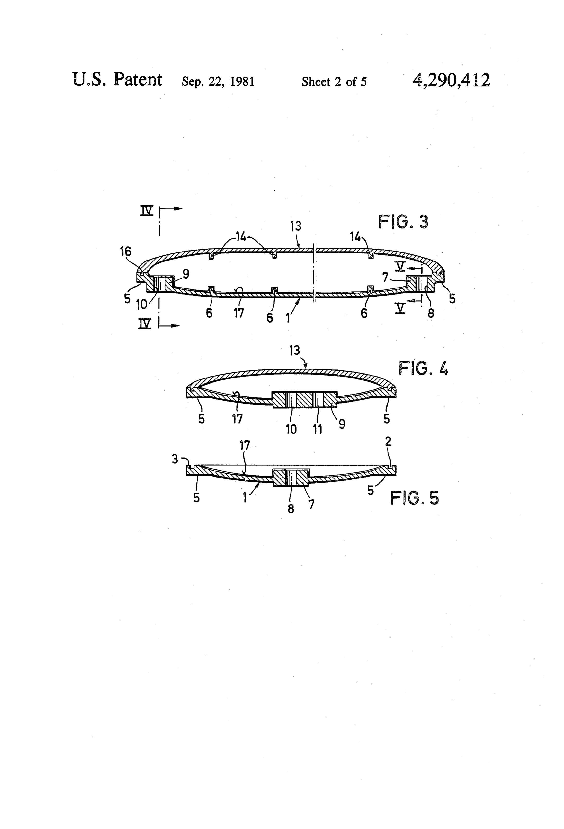
thermal loss of the absorber in upward direction to 40 FIG. 2 is a top plan view of the cup-shaped cover obtain a heat storage in the absorber when solar radia portion of the collector of FIG. 1;
tion decreases. The double cover collector involves the FIG. 3 is a longitudinal sectional view of the solar Same disadvantages in its structure and use as the mono collector composed of the cup-shaped bottom portion cover single collector. and the cup-shaped cover portion; The solar collector disclosed in U.S. Pat. No. 45 FIG. 4 is a cross-sectional view along the line 3,916,871 discloses the use of a vacuum pump con IV-IV of FIG. 3;
nected to the hollow body containing the absorber. The FIG. 5 is a cross-sectional view along line V-V of vacuum pump is used to evacuate the hollow body from FIG. 3;
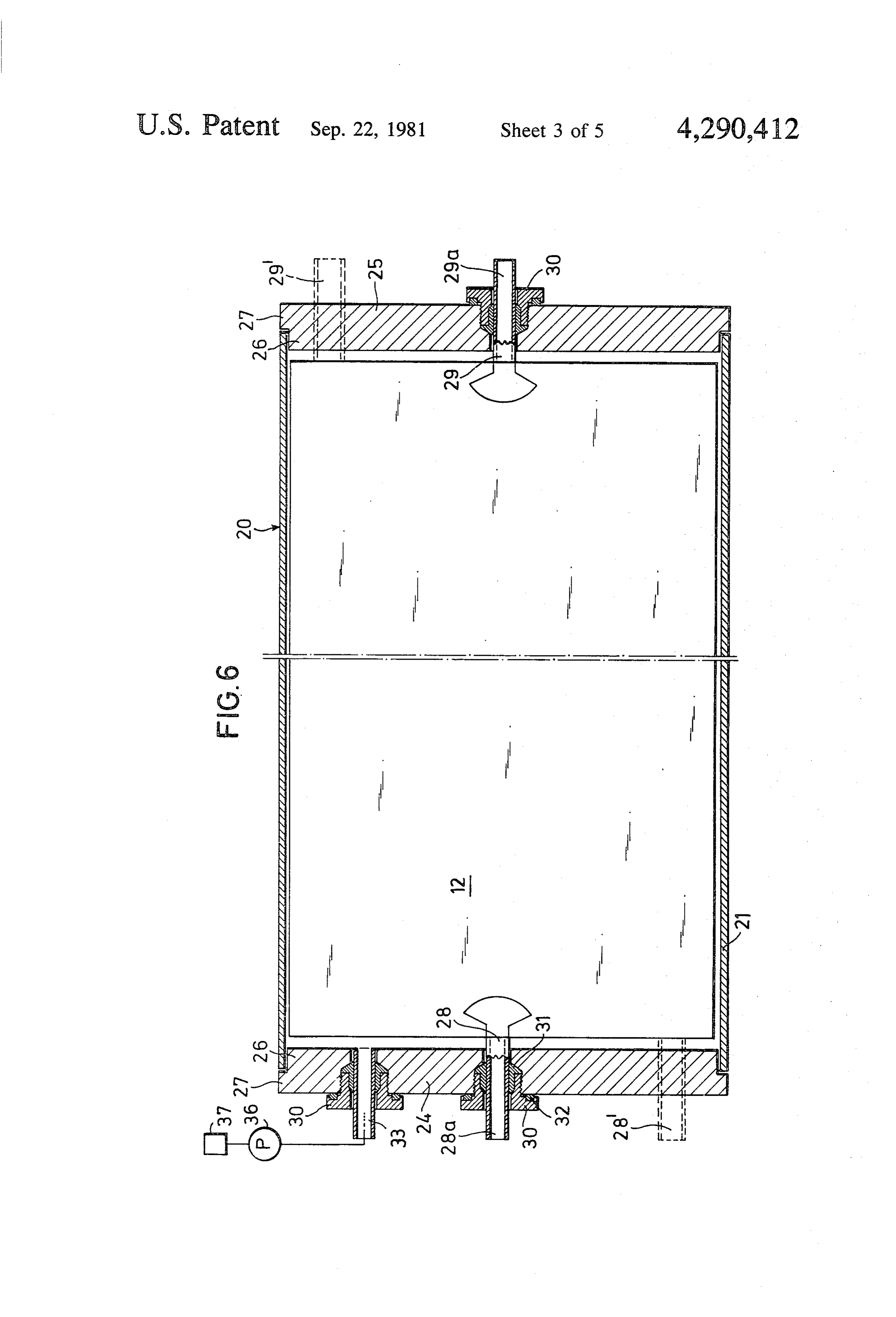
time to time and maintain a constant pressure level. The FIG. 6 is a longitudinal cross-section of another em vacuum in the hollow body insulates the absorber to 50 bodiment of a solar collector made in accordance with thereby eliminate the necessity for insulating packages this invention;
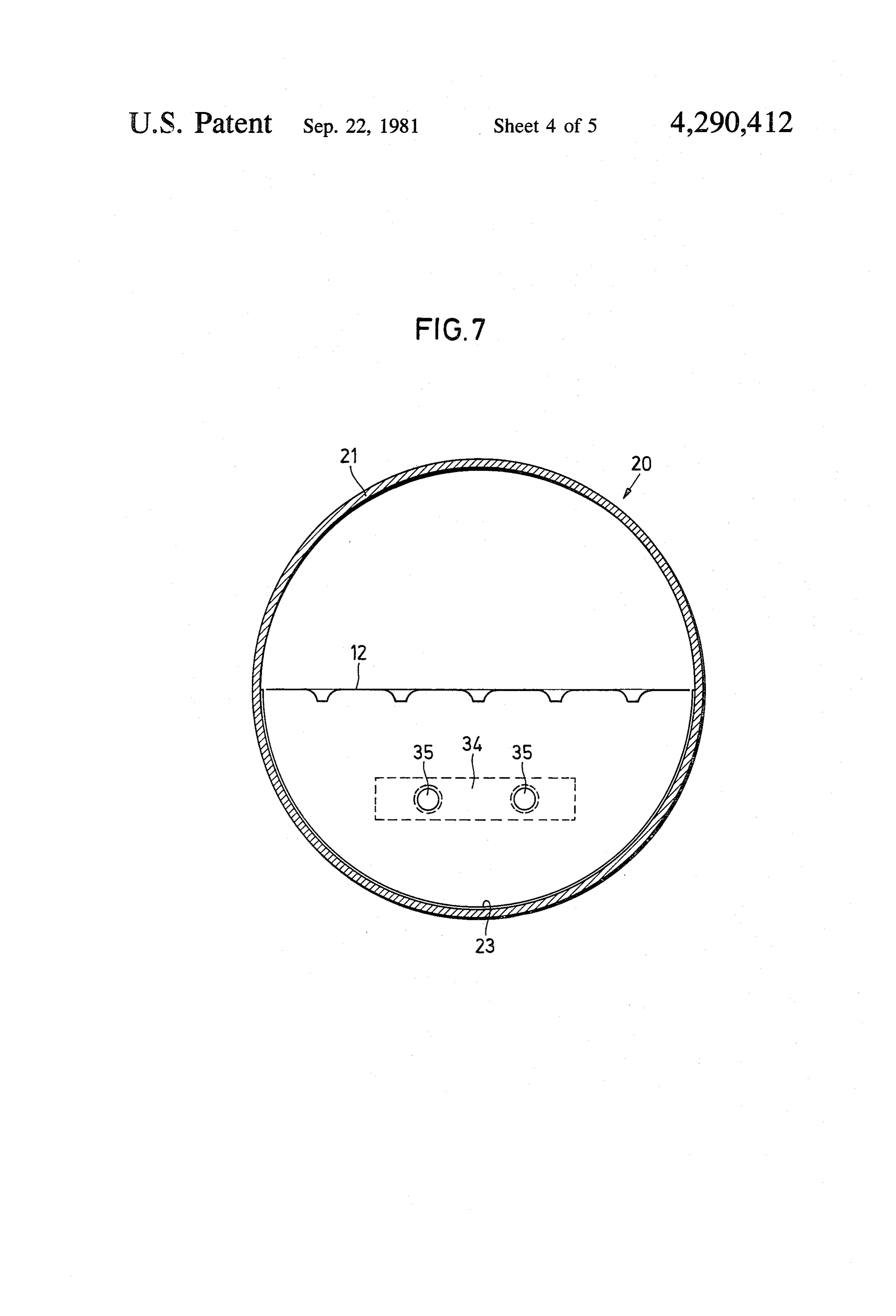
thus permitting the construction of the solar collector FIG. 7 is a cross-sectional view along a transverse with a more compact structural configuration. plane of the solar collector as shown in FIG. 6; SUMMARY OF THE INVENTION FIG. 8 is a plan view of a bottom plate of the absorber 55 in a solar collector made in accordance with this inven
The primary object of the invention is to operate a tion;
Solar collector having an absorber disposed within a FIG. 9 is a sectional view along line IX-IX of FIG. housing connected to a vacuum pump having a means 8 having a mounted cover plate thereon;
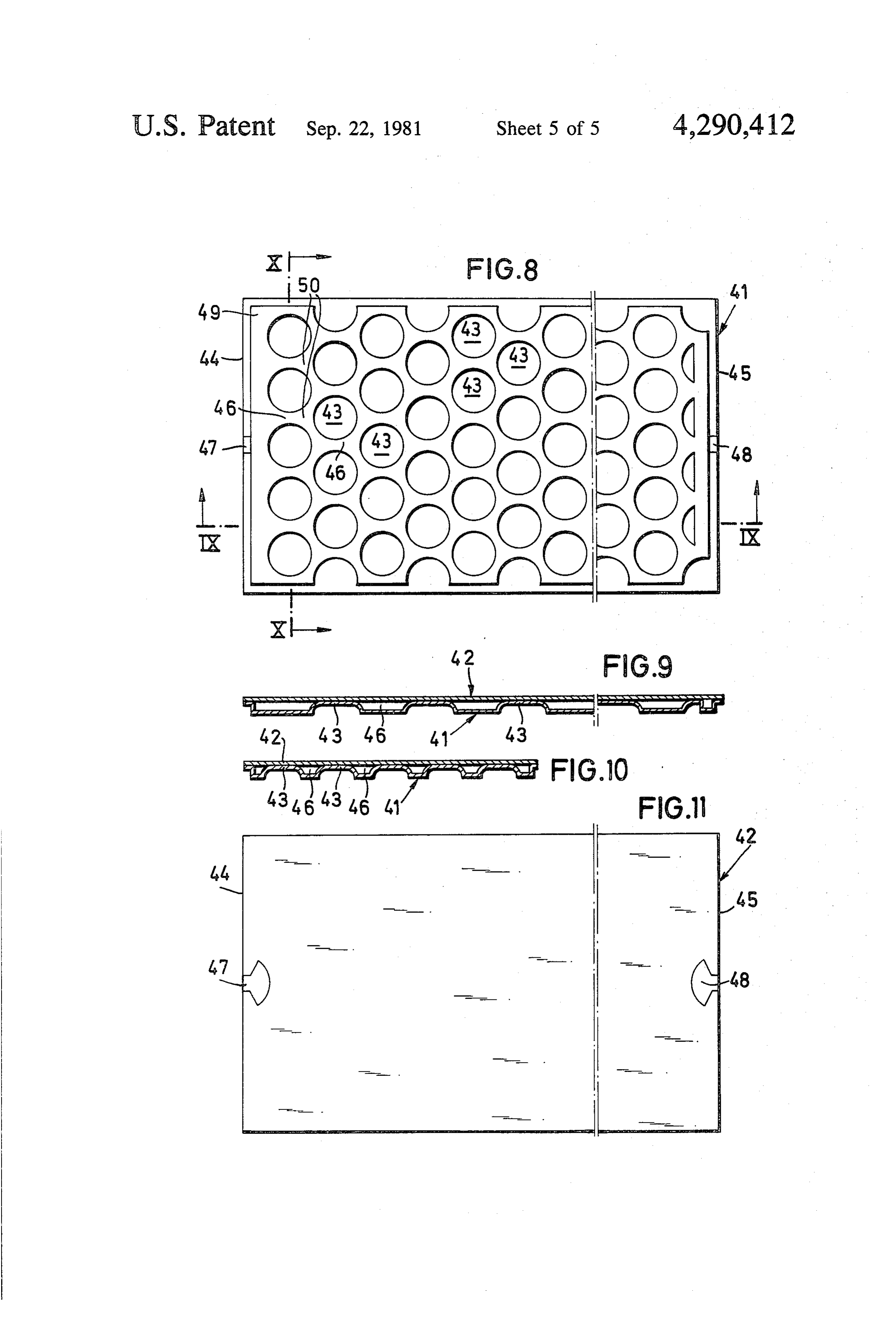
for controlling the vacuum within the collector to cor FIG. 10 is a sectional view along line X-X of FIG. respond to the prevailing conditions of thermal radia 60 8 with a mounted cover plate thereon; and tion and to the prevailing demand of heat of the con FIG. 11 is a plan view of the cover plate as shown in Sumer while an optimum output of the absorber is ob FIGS. 9 and 10.
tained.
Detailed description
Another object of the invention is to provide a solar collector having suitable constructional shapes to per 65 Referring to FIGS. 1 through 5, a solar collector mit its assembly in dwelling houses and the like. includes a bottom portion, generally designated , and a A further feature of the invention is to provide a cover portion, generally designated 13. Bottom portion particular structural configuration of an absorber useful 1 may be made of glass such as acrylic glass or of metal 8 and has a substantially rectangular shape in plan view There is very little danger of implosion with respect to and be cup-shaped in cross-section. The cup-shaped the structure of the solar collector while operating cross-section is shallow and free of edged corners. A under vacuum conditions. Control means 37 may be peripheral groove 2 is located around the edge of bot used to automatically control vacuum pump 36 to main tom portion 1. A supporting edge 3 is extended at cor tain the appropriate environment inside the solar collec ners 4 to facilitate assembly of the solar collector. tor with respect to the prevailing conditions outside the As noted, bottom portion 1 may be made of metal or collector.
any transparent material. When glass or transparent The vacuum in the vacuum-proof collector substan material is used, bottom portion should have a reflect tially surrounds and insulates absorber 12 from all sides. ing internal face. When bottom portion 1 is composed of 10 There are no heat losses of absorber 12 to the top, to the metal, the reflectivity of a polished face will provide the bottom, or to the sides thereof. The flat construction of necessary reflecting characteristics. A reflective coat collector 12 contributes significantly to substantially ing 17 is shown on bottom plate 1 in this first embodi improving the efficiency of the collector. That is, there ent. are no overshadowing effects of absorber 12 even with A supporting edge 5 is located at the under side of 15 an inclined incidence of the sun rays. If the heat be bottom portion 1 and is straight in cross-section without comes too intense or too high as in summer, the collec a curvature. Transverse ribs 6 extend along the inner tor housing will be ventilated, the insulation of absorber surface of bottom portion 1 to allow the walls to be 12 is suppressed and any surplus heat is exhausted to the made as thin as possible in cross-section. atmosphere.
An opening 8 is located in a reinforced zone 7 at one 20 Thus, the primary advantage of a solar collector end of bottom portion 1 and two openings or apertures made in accordance with this invention is its adaptabil 10 and 11 are located in a broader reinforced zone 9 at ity to prevailing conditions of heat radiation and corre the other end thereof. An absorber (not shown) is sponding demand of heat by the consumer by changing placed into cup-shaped bottom portion 1 and includes the insulating effect of the vacuum inside the collector. an output or outlet extending through opening 8 and an 25 The insulating effect may be completely neutralized at input or inlet extending through opening 10. A vacuum any time so that absorber 12 is no longer insulated to the pump (not shown) may be connected to the absorber outside. On the other hand, it is possible to apply a high through opening 11 and incorporate an adjustment vacuum to increase the insulating effect. A continuous means for controlling the pressure within the absorber. regulation may be effected between the two extreme This connection may be as shown in conjunction with 30 points by corresponding control of vacuum pump 36. the embodiment of FIG. 6. As noted above, the double shell body of the collector Cover portion 13 conforms to bottom portion 1 in may be open to the atmosphere thereby completely that it is rectangular and has a flat, cup-shaped cross cancelling the effect of a vacuum. When increased insu section reinforced by transverse ribs 14. A continuous lation is required due to reduced solar radiation, vac peripheral rib 16 is located along its outer edge 15 and 35 uum pump 36 is put into operation and evacuation of the fits' into peripheral groove 2 of bottom portion 1 when collector is effected. Operational losses of this type of assembled to form the flat hollow body of the solar an arrangement are extremely low due to possible collector made in accordance with this invention. The abrupt changes of characteristics of the solar collector. engaged peripheral rib 16 and peripheral groove 2 may Empirical data shows that the efficiency of the collector be bonded to each other to obtain a vacuum proof con in the present invention is twice as high as that of nection between the bottom portion 1 and top cover 13. known collectors.
The absorber disposed therein is mounted contactlessly A further embodiment of the invention is shown in to all sides of the hollow body of this collector. FIGS. 6 and 7. The solar collector 20 comprises a cylin The shallow cup-shaped cross section of the solar drical tube 21 composed of acrylic glass or any other collector body permits its integration into the roof 45 transparent material resistant to weather. Tube 21 forms membrane of a building. The resulting flat hollow body a housing for absorber 12 having a flat design and di is free of any corners. Thus, the bottom portion 1 has no mensions adapted to the interior of tube 21. Absorber 12 high edges so that the absorber housed within the dou is disposed at substantially the longitudinal center of ble shell collector body is fully exposed at any point on tube 21 to obtain the maximum width of absorber 12. In its surfaces by the sun rays even when at an extreme 50 this embodiment, the top half of tube 21 is transparent inclined degree of radiation. Furthermore, the disclosed so that the full solar radiation will act on the surface of structure prevents overshadowing or reflection and the absorber 12. An internal reflective coating 23 is dis output of the absorber disposed within the hollow body posed on the inside of the lower half of tube 21 as collector is always at optimum efficiency. It is impor shown. Coating 23 is covered by a transparent protec tant that a certain curvature is associated with both the 55 tive varnish layer (not shown). An outer reflective coat bottom portion 1 and top cover portion 13 to enable ing may be used on the outside of the lower half of tube them to catch the pressure acting from the outside even 21 which is turned away from the sun instead of the if the walls of the body are relatively thin. The straight internal reflective coating 23. The lower half of tube 21 or flat supporting edge 5 facilitates the assembly of the may be covered by a dark colored of protective varnish. solar collector onto an under frame or the like structure. 60 Circular front plates 24 and 25 may be made of The solar collector of this invention designed as flat acrylic glass or the like and close the two ends of tube hollow body is supplied and assembled with the interior 21. Each front plate 24 and 25 has a plug-type design thereof at ambient pressure. With vacuum pump 36 with a plug portion 26 protruding into the end of tube attached to the vacuum connection opening 11, it is 21 and another portion having a flange ring 27 resting possible to achieve the desired evacuation of the solar 65 against the outer edge of tube 21. Thus, front plates 24 collector at any desired moment. The vacuum may be and 25 form end covers which may be bonded to the increased to any amount or completely eliminated ends of tube 21 or connected in any other desired form thereby controlling the efficiency of the solar collector. to establish a vacuum proof seal. When the solar collec 9 tor 20 is under vacuum, the outer pressure on tube 21 rigid mounting of absorber 12 is casured. Solar coilec urges the two balls against plug portion 26 to insure the tor 20 may be mounted vertically or in inclined standing tightness of the interior of tube 21. The plug portions 26 position or horizontally or in an inclined lying position. impart an internal supporting quality against the force Rotation of the tube 23 provides angular adjustment of exerted by the vacuum from inside tube 21. Apertures 5 absorber 12 about its longitudinal axis as disciosed are located in each front plate 24 and 25 for effecting the herein, Thus, it is possible to adapt collector 2 to the connection of absorber 12 and vacuum pump 36. Ab conditions of radiation and to constructional and local sorber input 28 extends through the opening in plate 24 prerequisites at the mounting site where necessary. and absorber output 29 extends through the opening in The tubular collector 20 offers relativeiy small sur front plate 25. Connecting pipes 28a and 29a protrude O faces of attack to wind when disposed in a horizontal outside the respective front plates 24 and 25 and may be assembly. Thus, the requirement for expensive holding fitted with external threads, olive profile or the like (not mechanisms is eliminated. When in a vertical position, shown). The apertures in plates 24 and 25 are located in solar collector 20 may have a relatively small diameter the center thereof and in the same plane with absorber so that it can be fitted very easily to the prevailing 12. Connecting pipes 28a and 29a extend through 15 building conditions and in a constructional form which threaded bushings 30 which have sealing washers 31 attracts no attention.
and 32 which are composed of high temperature plastic The waii thickness of tube 23 is sufficient to realize material. Thus, a vacuum proof feed construction is the maximum incidence of sun radiation thereihrough effected with respect to the input and output connec on absorber 12 while maintaining sufficient stability due tions 28 and 29, respectively. Threaded bushings 30 are 20 to its geometric cross-sectional design go that it may be extremely suitable when solar collector 20 is used for suspended at both ends without an interrinediate sup energy production. A potting compound such as molten port. Additionally, the wall thickness must be sufficient acrylic glass may be used to seal input and output con for tube 21 so that it is sufficiently stable to withstand nections 28 and 29 when solar collector 20 is designed the vacuum existing inside collector 23. to operate at low temperatures. 25 A potting compound may be used to bond or consoli Under certain circumstances, it may be advantageous date the connection between tube 21 and front plates 24 to provide the input and output connections at a lateral and 25 to ensure a vacuum proof sea. As noted, the position 28' and 29' respectively, rather than in the ends of tube 21 are reinforced internally by the plug center of front plates 24 and 25. Connections 28' and 29 portions 26. An axially symmetrical tube body may are also maintained in the plane of absorber 12 however. 30 have an optional shape, e.g., one end at least may have A connecting pipe 33 is disposed in an additional a contracted neck configuration.
aperture of front plate 24 to connect vacuum pump 36 At least one of the two end plates 24 and 25 should be to the inner chamber of tube 21. A threaded plug 30 transparent in one partial zone, if necessary, the other mounts connecting pipe 33 in a vacuum proof manner. end cover may have at least one partial zone with a The specific location of connecting pipe 33 in front 35 reflective coating having a protective warnish thereon. plate 24 is optional with respect to absorber 12. A con The selection of the two types of end cover is dictated trol means 37 is used to maintain an automatic switching by the position of solar collector 20 when mounted in of the vacuum pump 36 on and off to change the vac either a standing or lying position. it is imperative that uum in tube 21 and thus the insulation qualities of ab a non-transparent end cover should not cause overshad Sorber 12 accordingly. As is evident as disclosed herein, 40 owing or reflections on absorber 2. Thus, a transparent control means 37 constitutes a heat or thermal radiation end cover should be used where the inclined incidence Sensing device which is directly connected to a switch of sun rays are to impinge upon each point of the sur for the vacuum pump 36. face of the absorber 2 so that maximum output of the The tubular shape of solar collector 20 enables low collector 20 is achieved.
cost construction through the use of standard elements 45 As shown in FIG. 7, a strip 34 is mounted to the requiring little expenditure as to tools. The large hollow surface of front plates 24 and 25 within the reflected Space volume at both surfaces of absorber 12 provides coating zone of tube 21. Strips 34 consist preferably of excellent insulating effect even with the application of a the same material as tube 21 to obtain an accommoda low vacuum. Absorber 12 is mounted so that it may be tion of the expansion behavior of the material. Strips 34 introduced from one end of tube 12. An end wall por 50 preferably extend in a direction parallel to the plane of tion integrally formed with the tube wall may be used in absorber 12. Each strip 34 has several threaded bores 35 place of one end cover. Thus, only one front plate 24 or into which fixing bolts may be screwed for the assembly 25 will be used with the distribution of apertures therein of solar collector 23 at a supporting fraine construction. provided accordingly. In either case, it is possible to fit As noted above, front plates 24 and 25 finay be trans all openings in one end cover only. Production can be 55 parent to avoid overshadowing effects as shown in the facilitated further when all openings for connections are drawings. Alternatively, one or both front plates 24 and only provided in end covers while the tube jacket is free 25 may have a reflective coating with a protective war of any perforations. nish at least in a partial area. This, of course, will de With tube 21 free of any openings, there is no risk that pend upon the particular position of operation of solar fissures or breaks will form therein thereby jeopardizing 60 collector 20. As further noted above, the openings in the vacuum tightness of solar collector 20. Further the end plates 24 and 25 may be fitted either in the more, there is no requirement for reinforced zones to be center thereof or at opposite sides at the edges thereof. located in the tube jacket. Thicker material may be used it is the purpose of such alternatives to excluse hydro in end plates 24 and 25 thereby facilitating the formation static problems depending upon the position of solar of holes therein through a simple and non-critical opera 65 collector 20. Such problems cause a decrease of effi tion without concern of forming cracks. ciency of the solar collector and are brought about, for With the absorber input 28 and output 29 disposed in example, when the coilector 20 is mounted i? a lying the openings of end covers 24 and 25, respectively, the position with the absorber 12 fitted at an angle with 10 respect to the horizontal plane. Thus, the fluid current utive row thereafter. The fluid medium takes up the in the upper portion of absorber 12 is different from that heat generated in each of the zones by solar radiation as in the lower portion. This difference is compensated by it moves between the consecutive rows of bulges 43 the eccentric arrangement of the input and output of the through the constricted channels 46. The whirling prin absorber 12. Both the central and offset positions of ciple continues to work in different modes within the openings in end plates 24 and 25 are maintained in the total absorber and is analagously applicable to all chan plane of absorber 12 so that its assembly is facilitated by nels 46 and zones of confluence 50. A large amount of a straight extension of the absorber input and output turbulence is effected in the zones of confluence 50 and lines through the openings. The connecting pipes 28a thereby causes an improved heat transfer to the work and 29b are attached by the threaded bushings of high 10 ing fluid medium and an increase in efficiency of the temperature plastic when the collector 20 is operating absorber.
at temperatures above about 120. As already stated, Thus, this construction of the absorber causes the potting material may be used to embed connecting pipes 28 and 29a when collector 20 is operating at lower current of liquid to be distributed by branching into partial currents so that highly turbulent zones are temperatures. 15 formed over the total surface of the absorber. Due to Efficiency of solar collector 20 is further improved the narrow channels between adjacent interference through the particular configuration of the absorber 12, points of a first group of interference points, the work details of which are more specifically shown in FIGS. 8 ing fluid medium is first subdivided into several small through 11. As shown, the absorber includes a bottom currents where it takes up a large amount of heat gener plate 41 turned away from the sun and a cover plate 42. 20 ated in the absorber zone. After the first interference Each of the plates 41 and 42 may be made of metal sheel points have been surrounded material. A cavity is formed between the cover plate 42 tial currents of liquid unite tobyform the flow, any two par one common fluid and the bottom plate 41.
A plurality of circular bulges 43 are pressed into current in a channel zone of a greater volume. A vortex bottom plate 41 with a flat surface being contiguous to 25 is created in the channel zones and will penetrate into the cover plate 42. Bulges 43 are arranged in straight the subsequent channels of reduced cross-section be transverse rows extending in a direction parallel to the tween the interference points of another subsequent end edges 44 and 45 as shown. Consecutive rows of group thereof.
bulges 43 are offset with respect to each other so that The efficiency of the absorber made in accordance the bulges 43 are transversely offset with respect to 30 with this invention is more than 10% higher than that of each other in the fluid flow direction. Thus, an interfer known absorbers. The simple construction of the ab ence point is always established after the rectangular sorber as disclosed herein permits an inexpensive pro channels 46 which are formed between two adjacent duction thereof. The particular absorber structure es bulges 43 of any row. The interference point provides a tablishes an optimum turbulent current which is pro positive whirling motion to the liquid flow through the 35 duced and maintained purposefully over the total sur absorber. face of the absorber. The resulting heat delivery is sub The working medium is a fluid which flows through stantially quicker and better thereby establishing a the inlet 7 through the labyrinth of channels 46 to the greater efficiency of operation than any absorber hav outlet 48. The fluid is heated by the solar energy which ing other known geometrical configurations. is then converted into other forms of energy such as 40 As discussed above, the collecting zone 49 serves to heat during the course of travel of the fluid through the relieve the absorber input 47 of any jamming effects. absorber. The heated working fluid medium is removed Further, while the circular bulges 43 as illustrated in from the absorber through outlet 48 and fed to any the drawing are very advantageous, the selected ar desirable place thereafter. rangement, dimension and relationship of other forms of The fluid medium entering inlet 47 first gets to a fluid 45 interference points may be chosen. For example, the collecting zone 49 which extends across the absorber bulges 43 may have a rectangular design to achieve an ahead of the first row of bulges 43. The fluid is distrib angular flow in the working fluid medium. Further uted from the fluid collector zone 49 into the channels more, rather than press profiles in the bottom plate 41, 46 to form several small fluid currents. The bulges 43 individual bodies may be fitted and distributed so as to symmetrically arranged on the bottom plate 41 effect 50 insure that the principle of the whirling of fluid medium this condition of fluid flow. The fluid medium which by using narrowed channels ending in enlarged and flows around the first row of bulges 43 takes up the heat branching zones of confluence is maintained. generated in this zone by solar radiation. The channels While the solar collector assembly and process for 46 unite after the first row of circular bulges 43 and operating same has been shown and described in detail, form a common fluid current in a larger triangular zone 55 it is obvious that this invention is not to be considered as 50 having a larger volume. One side of the triangular being limited to the exact form disclosed, and that zone of confluence is already formed by the next row of changes in detail and construction may be made therein circular bulges 43. A whirl is formed in the fluid me within the scope of the invention, without departing dium by the confluence of two partial currents each in from the spirit thereof.
one of the nearly triangular zones 50. This whirl contin 60 I claim:
ues to develop as it moves into the following con 1. A solar collector assembly comprising: stricted channels 46 formed between subsequently dis (a) a hollow housing at least partially transparent to posed consecutive rows of bulges 43. solar rays,
The whirl formation decreases to a large extend in the (b) absorber means disposed in the housing to receive channels 46 between the bulges 43 of the consecutive 65 said solar rays, channels. However, the whirl formation is revived (c) vacuum pump means connected to maintain a again with the confluence of the individual partial cur normally vacuum insulating effect around the ab rents after the second row of bulges 43 and each consec sorber means inside of the housing,
Page 11scan →
(d) means for sensing the heat radiation of prevailing 15. An assembly, as defined in claim 12 wherein ambient atmospheric conditions, and at least one of the two end covers is transparent at (e) switching means responsive to said sensing means least in a partial zone. to turn off the vacuum pump means and ventilate 16. An assembly as defined in claim 12 wherein to completely neutralize said insulating effect. at least one of the two end covers includes at least one 2. An assembly as defined in claim 1 wherein partial zone having a reflective coating with a pro said absorber means includes an inlet and an outlet, tective varnish layer.
the hollow housing is a tube having opposed ends 17. An assembly as defined in claim 12 wherein closed with end covers in a vacuum-proof manner, the tube is axially symmetrical, preferably cylindrical the end covers include apertures for inlet and the 10 and made of glass, acrylic glass or another trans outlet which are located substantially in the tube parent material.
center and one of the apertures for connection of 18. An assembly as defined in claim 12 wherein the vacuum pump means. . the tube has an internal or outer reflective coating 3. An assembly as defined in claim 2 wherein with protective varnish layer on one longitudinal the one end cover includes apertures for the absorber 15 half.
inlet and the connection of the vacuum pump 19. An assembly as defined in claim 18 wherein the protective the other end cover has an opening for the absorber ing is transparent. varnish layer of the internal reflective coat outlet.
4. An assembly as defined in claim 2 wherein 20 20. An assembly as defined in claim 18 wherein three openings are formed in one end cover. the protective varnish layer of the outer reflective 5. An assembly as defined in any one of the claims 2 coating is of a dark color. to 4 wherein 21. A solar collector assembly comprising: the openings for the absorber inlet and outlet are (a) a hollow housing at least partially transparent to located in the center of the end covers. 25 solar rays, 6. An assembly as defined in any one of the claims 2 (b) absorber means disposed in the housing to receive to 4 wherein said solar rays, the openings for the absorber inlet and outlet are (c) vacuum pump means connected to the housing to located at opposite sides at the edge of the end evacuate the inside of the housing, COWerS. 30 (d) means for sensing the heat radiation of prevailing 7. An assembly as defined in any one of the claims 2 ambient atmospheric conditions, and to 4 wherein (e) means responsive to said sensing means to auto connecting pipes are positioned in a vacuum proof matically control the vacuum pump means and manner and protruding to the outside of said open thereby adjust vacuum within the housing in re 1ngS. 35 sponse to changes in prevailing atmospheric condi 8. An assembly as defined in claim 7 wherein tions, the connecting pipes are fastened by potting material (f) said hollow housing comprises a shell-shaped or the like in the end cover openings in a vacuum curved bottom portion connected in a vacuum proof manner. proof manner with a shell-shaped curved cover 9. An assembly as defined in claim 7 wherein 40 portion.
the connecting pipes are secured in the end cover 22. An assembly as defined in claim 21 wherein openings in a vacuum-proof manner with a a cavity including fluid channels formed between a threaded plug and seals made of a high temperature cover plate and a bottom plate and extending from resistant plastic. an end-side input to an end-side output, 10. An assembly as defined in any one of the claims 2 45 said cavity including a plurality of local interference to 4 wherein points in a fixed relationship to rectangular fluid at least one strip is secured on the outer surface of the channels, two end covers, said interference points being transversely offset with each said strip includes threaded bores to receive respect to each other in the fluid direction and bolts for mounting the assembly. 50 being effective to positively whirl up the fluid 11. An assembly as defined in any one of the claims 2 flow.
to 4 wherein 23. An assembly as defined in claim 21 wherein the end covers of the two tube ends comprise front the cup curvatures of the bottom portion and of the plates mounted in a vacuum-proof manner. cover portion are shallow.
12. An assembly as defined in any one of the claims 2 55 24. An assembly as defined in claim 21 wherein to 4 wherein the double shell-body has a substantially symmetrical the one end cover comprises a formed wall portion of lancet cross-sectional shape. the tube, and the other end cover comprises a front 25. An assembly as defined in any one of the claims 21 plate inserted in a vacuum-proof manner into the to 24 wherein opposed end of the tube. 60 the bottom portion and the cover portion are made of 13. An assembly as defined in claim 11 wherein glass, acrylic glass, or another transparent material. each front plate is a disk fitted to project into the tube 26. An assembly as defined in any one of the claims 21 and having one flange ring resting against the outer to 24 wherein edge of the tube. the bottom portion is made of metal and the cover 14. An assembly as defined in claim 11 wherein 65 portion is made of glass, acrylic glass or another the front plates are made of a transparent material and transparent material.
are bonded to the tube ends in a vacuum-proof 27. An assembly as defined in any one of the claims 21 flanner. to 24 wherein 12 a reflective coating is disposed on the inner face of the bottom portion has at both ends one opening each for said inlet and outlet and another opening for the bottom portion. connection of the vacuum pump means. 28. An assembly as defined in any one of the claims 21 31. A process for operating a solar collector including to 24 wherein 5 a hollow housing containing an absorber, and said hous the bottom portion and the cover portion include ing being connectd to a vacuum pump, said process reinforcing ribs at their inner surface, and comprising:
a groove pointing to the top is located along the edge (a) maintaining a normally vacuum insulating effect around the absorber disposed inside of the housing, of the bottom portion. 10 (b) sensing heat radiation existing in prevailing ambi 29. An assembly as defined in any one of the claims 21 ent atmospheric conditions, to 24 wherein (c) switching off the vacuum pump for ventilating the the bottom portion includes an edge having an under inside of the housing to completely neutralize said side with a straight design without a curvature to 5 insulating effect in the housing in response to the form a supporting edge. amount of heat radiation determined in the sensing step, and 30. An assembly as defined in any one of the claims 21 (d) said switching off step of the vacuum being effec to 24 wherein tive to control the efficiency of the fungtion of the the absorber means includes an inlet and an outlet, absorber.
Provenance
- Collection
- Patents citing this work
- Pages
- 12
- Method
- pdftotext (the PDF's own text layer) + pdftoppm 300dpi page scans
- Patent office record
- patents.google.com →
- Source
- Google Patents citing-documents table
- Assignee
- Walter Steinrucke
- Published
- 1981-09-22
- Transcribed from
- patentimages.storage.googleapis.com →