

patent · US4076015A
Solar energy collector
28 February 1978
Text
Page 1scan →
United States Patent (19)
Mattson
54). solar energy collector
(76 Inventor: John P. Mattson, 123 Lake Shore
Drive, Duxbury, Mass. 02332
Related U.S. Application Data (63. Continuation-in-part of Ser. No. 621,759, Oct. 14, 1975, abandoned.
51) Int. C.’................................................. F24J 3/02 52 U.S. C. ..................................... 126/271; 126/270
921,976 5/1909 Glass ................................... 126/271 2,213,894 9/1940 Barry ........ ... 126/27 2,625,930 l/1953 Harris................... ... 126/270 3,244,186 4/1966 Thomason et al. .. ... 26/270 3,985,116 10/1976 Kapany ................................ 126/270
Primary Examiner-Kenneth W. Sprague
Assistant Examiner-James C. Yeung
Attorney, Agent, or Firm-Edward A. Gordon
An apparatus for collecting radiant solar energy upon an energy receiving surface comprising a solar energy collecting module having a base and a plurality of radi ant energy collector module units angularly disposed to said base. The collector units consist of a raised surface or surfaces transparent to incident solar energy. The configuration and angles of the collector module unit surfaces with respect to the base and the energy receiv ing surface are varied to provide optimum collection of solar radiation. The invention also provides for a plural ity of reflective surfaces angularly disposed to the base and energy receiving surface where a combination of transparent and reflective surfaces provide for optimum collection of radiant energy. The reflective surfaces are angularly disposed to the base to reflect incident radiant energy to an adjacent transparent surface for transmis sion to the energy receiving surface.
5 Claims, 10 Drawing Figures
Drawings
Page 2drawing sheetscan →
Page 3drawing sheetscan →
Page 4drawing sheetscan →
Page 5scan →
It is also desirable to provide a radiant solar energy
SOLAR ENERGY COLLECTOR collector capable of simple modular construction, styl This application is a continuation-in-part of my co ish in appearance, which can be installed on existing pending application Ser. No. 621,759 filed Oct. 14, 1975, roofs regardless of location or pitch. abandoned.
Summary of the invention
Background of the invention
This invention relates to an apparatus for collecting 1. Field of the Invention radiant solar energy and more particularly to the radi This invention relates to an apparatus for collecting ant solar energy collector and the structure of modular radiant solar energy and more particularly to a solar 10 units.
energy collector which can be attached to a surface or In accordance with the present invention there is structure without regard to direction or angle of the provided an apparatus for collecting radiant solar en surface or structure upon which the collector is posi ergy upon an energy receiving surface for conversion to tioned. heat energy which is constructed and arranged to pro vide a modular unit having a base and a plurality of
There have been numerous systems proposed for the collector module units angularly disposed to module utilization of solar energy which generally comprise a base. The collector units are adjacently disposed to collector unit which directs solar energy on an energy form a plurality of hollow structures each having a receiving means which may be an evaporator unit or a surface or surfaces angularly disposed to the base of the conduit for a heat exchange medium. Unlike conven 20 modular unit to provide for transmission of incident tional fuel burning systems, such solar devices provide a solar energy to the energy receiving surface. Preferably non-polluting source of usable energy. In many prior art the structure is formed of four transparent surfaces systems large black aluminum collectors absorb the wherein at least three surfaces have a common vertex. sun's energy beneath rigid sheets of plastic. In these The invention also provides for a plurality of reflective systems the flat sandwich-like assembly is positioned to 25 surfaces angularly disposed to the modular base where be aimed due south and tilted at an angle of 45. While a combination of transparent and reflective surfaces such flat solar energy collector assemblies can be in provide for optimum collection of the radiant energy. stalled on an existing building with a flat roof surface, it The reflective surfaces are angularly disposed to reflect is not readily adaptable to existing structures having incident solar energy to an adjacent transparent surface inclined roofs and are particularly not suitable for in 30 for transmission to the energy receiving surface. Where clined roofs which run in a generally east-west direc transparent and reflective surfaces are employed to tion, for example, since they are then unable to utilize form the modular collector unit the transparent surfaces the total solar energy available. In such instances instal and reflective surfaces are adjacently disposed to form a lation may require the giving up of land around the 35 plurality of structures having a common base and building. For the home-owner the giving up of land wherein at least three surfaces have a common apex. may be too high a price to pay for lower heating costs. The structures preferably take the form of a hollow In other prior systems one or more reflector units are geometric pyramid having three or more sides to pro mounted on a framework which changes its inclination vide for transparent and/or reflective surfaces. An im in dependence upon the elevation of the sun, thereby 40 portant feature of this concept of the invention is that assuring that the reflected solar energy will always be the surfaces forming the collector unit can be varied in directed at the energy receiving means. These previous size as well as the angular relationship of the surfaces to systems impose severe restrictions on the size of the each other and to the modular base to provide for maxi reflector assembly since it must be capable of swinging mum collection of radiant energy. The shape of the movement in a vertical plane. 45 transparent and reflective surfaces is preferably flat In other prior systems frames have carried a plurality where a pyramidal configuration is employed, but may of individually inclinable reflector units of parabolic be curved in order to achieve maximum efficiency of cross-sections with each reflector unit having its own collecting radiant solar energy. The invention provides energy receiving means located at the focus of the pa an apparatus for collecting radiant solar energy regard rabola. In still other prior systems there is provided a 50 less of the angle or direction of the structure that it is single energy receiving means which receives reflected positioned upon.
solar energy from a plurality of individually inclinable The invention accordingly comprises the apparatus reflector units. possessing the construction, combination of elements The foregoing prior art, while providing solar energy and arrangement of parts which are exemplified in this collectors, do not provide a solar energy collector 55 disclosure and the scope and application of which will which is readily adaptable to a surface which points be indicated in the claims.
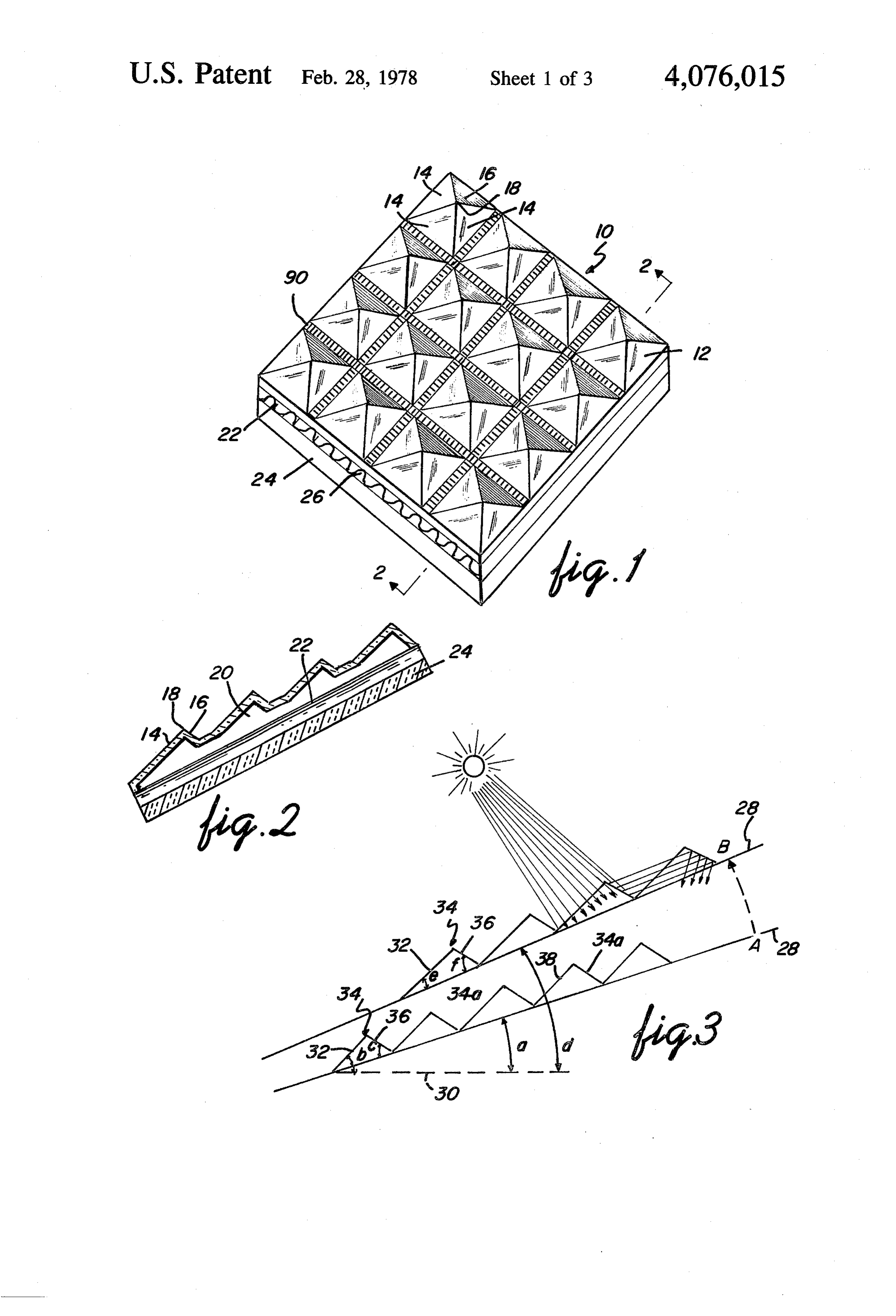
substantially in any direction and at optimum angles to horizontal or level while still providing effective collec DESCRIPTION OF PREFERRED tion of radiant solar energy. EMBODIMENTS It is, therefore, the desire of this invention to provide For a fuller understanding of the nature and desired an apparatus for collecting radiant solar energy which is objects of the invention, reference should be had to the readily adaptable to a surface which points in substan following detailed description taken in connection with tially any direction and inclined at optimum angles to the accompanying drawings wherein like reference horizontal or level while still providing effective collec characters denote corresponding parts throughout the tion of radiant energy. 65 several views and wherein: It is also desirable to provide a radiant solar energy FIG. 1 is a partially diagrammatic perspective view collector which provides structural rigidity and light of an embodiment of the invention illustrating a solar weight construction. energy collector module assembly having a plurality of 6 collecting units each having transparent and reflective such units have been properly masked, as is well known surfaces. by those skilled in the art.
FIG. 2 is a sectional view taken through 2-2 of FIG. In another embodiment of the invention the reflective 1 and illustrating the angular disposition of the surfaces, material may consist of a thin flexible sheet of plastic FIG. 3 is a diagrammatic view illustrating the change 5 material such as mylar upon which has been applied a in angular disposition of the transparent and reflective thin coating of reflective metal. Such sheet can be adhe surfaces as the angle of support is changed with respect sively applied to the surfaces to be employed as reflec to horizontal or level. tive surfaces.
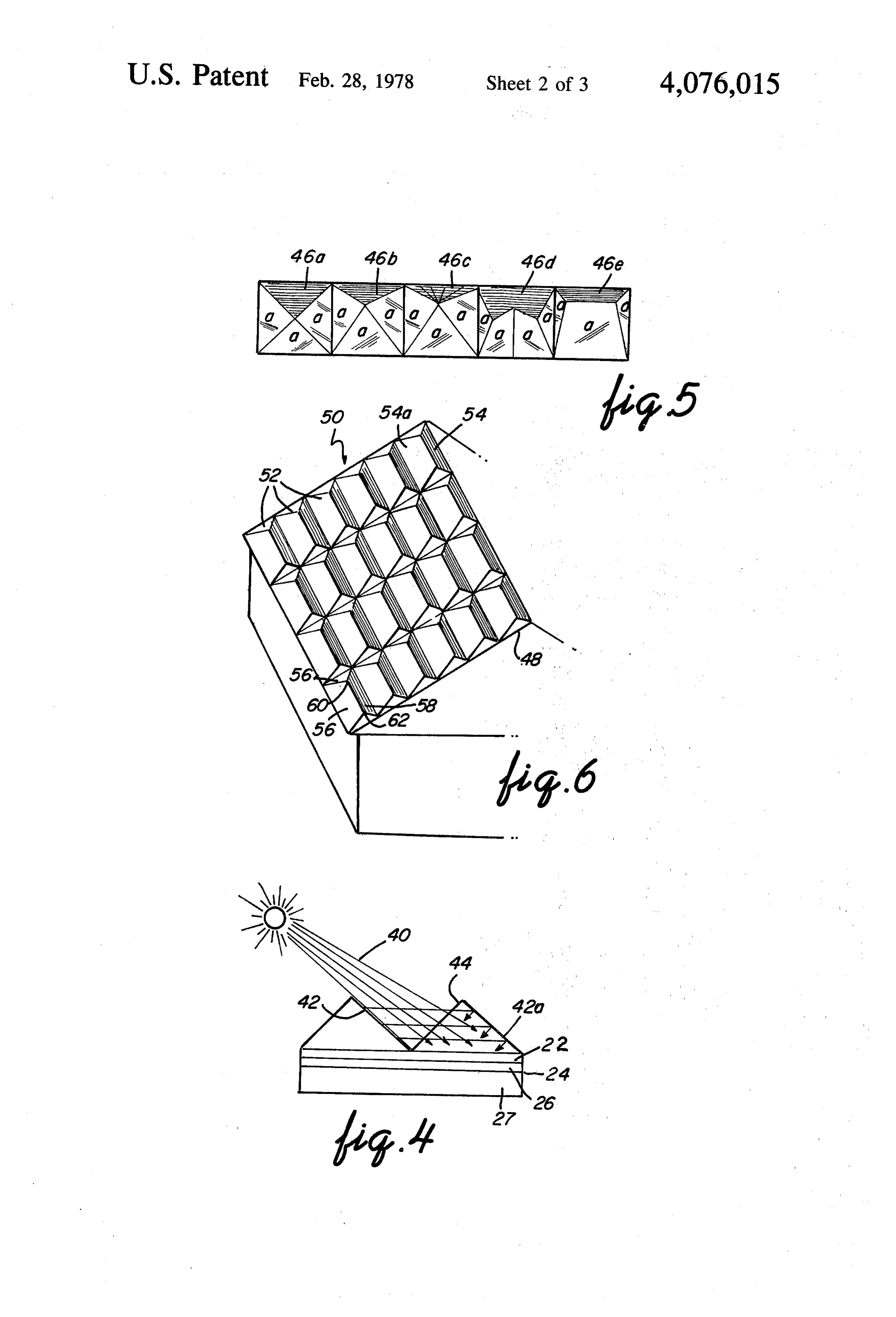
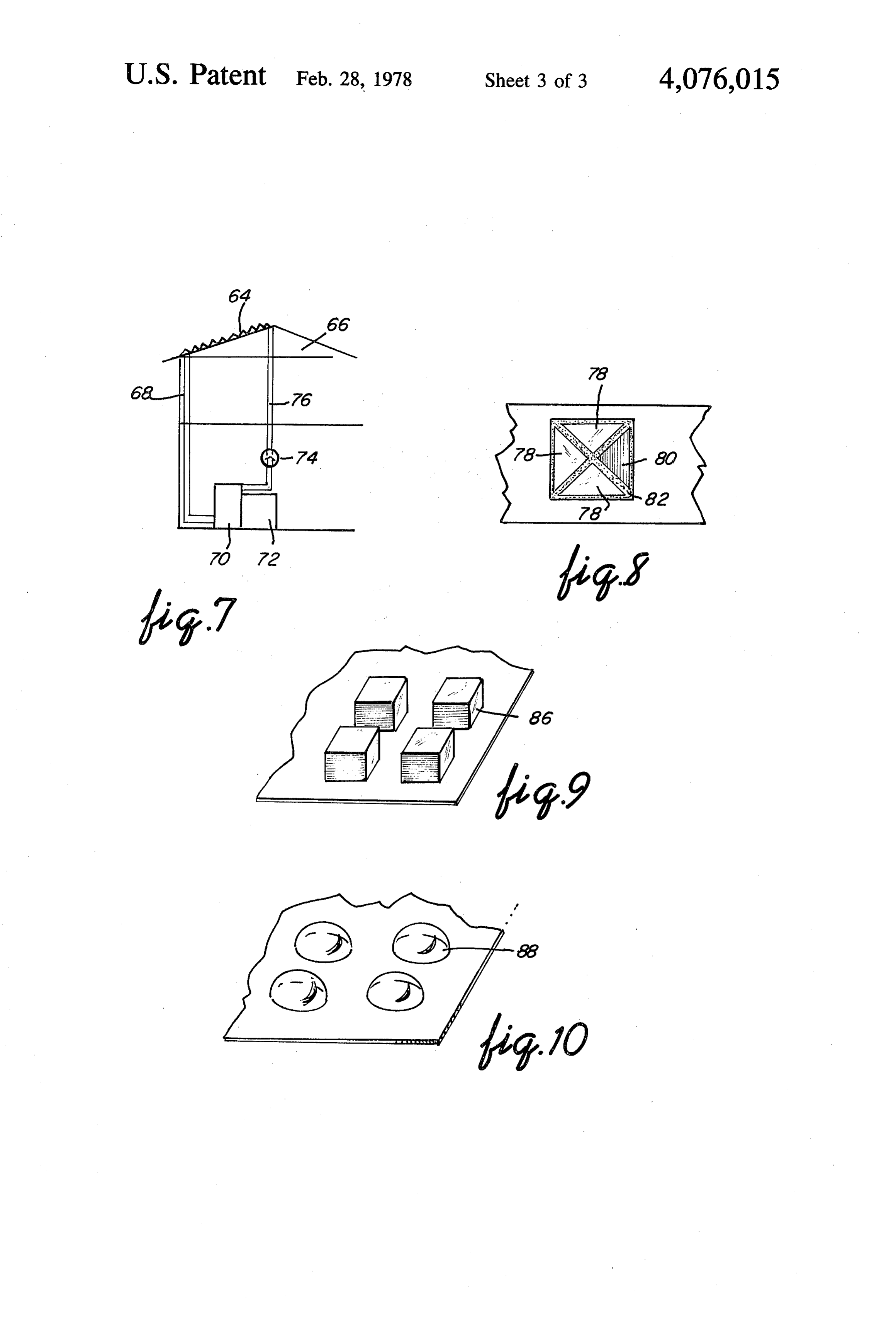
FIG. 5 is a top plan view of five embodiments of the The insulation means 24 can be formed of a plastic collector units illustrating pyramidal type collector O material such as styrofoam. Other suitable materials units within the scope of the invention. such as fiberglass, wood, and asbestos can also be used. FIG. 4 is a diagrammatic representation in section of The insulation 24 serves to insulate the structure (roof, apparatus constructed in accordance with the present for example) from transfer of heat from the collecting invention and illustrating the relationship between the 15 module, and the loss of heat from the energy receiving transparent surfaces and the reflective surfaces. means 22 through the bottom of the collecting module. FIG. 6 is a combination of a partially diagrammatic The energy receiving surface 22 is formed of a mate sectional and partially plan view illustrating modular rial which will absorb radiant energy or light energy collector with a plurality of collector units as applied to and convert it to thermal energy or heat energy and a roof structure. convert such thermal energy to a heat exchange fluid. FIG. 7 is a diagrammatic sectional view of the inven 20 In FIGS. 1 and 2 the energy receiving surface 22 is a tion as applied to a solar energy system for a building. sheet of metal such as stainless steel, aluminum or cop FIG. 8 is a fragmentary plan view of a modified em per corrugated to provide channels 26 through which bodiment of the collector unit in accordance with the the heat exchange fluid is passed. The upper surface is present invention. provided with a dull black coat to promote absorption FIG. 9 is a fragmentary plan view of a modified em 25 of the solar radiant energy. The black coating can, for bodiment of the collector unit in accordance with the example, be provided by a black paint or a layer of present invention. carbon black.
FIG. 10 is a fragmentary plan view of a modified Referring now to FIG. 3 of the drawing there is embodiment of the collector unit in accordance with 30 illustrated the change in angular disposition of the trans the present invention. parent and reflective surfaces as the angle or pitch of Referring now to FIGS. 1 and 2 of the drawing, there the supporting structure is changed or varied with re is shown generally at 10 a solar energy collector module spect to level or horizontal. As shown in FIG. 3 sup of the present invention having a plurality of collecting porting structure 28 is positioned at an angle a from line units 12, each having three transparent surfaces 14 and 35 30 representing horizontal. Transparent surface 32 of one reflector surface 16. The collector units 12 are modular unit 34 is then preferably disposed at angle b shown in the shape of a pyramid with four sides having from the supporting structure 28 so that the sum of a common apex 18 and defining a space 20. The trans angles a and b is 45 where such angle is optimum with parent surfaces 14 and reflector surfaces 16 are triangu respect to incident solar radiation. The angle c of reflec lar in shape. As particularly illustrated in FIG. 2 the tor surface 36 is selected to provide reflection of inci transparent surfaces and the reflector surfaces are dis dent radiant energy 40 to the transparent surface 38 of posed at an angle to the energy receiving means 22. The the adjacent module unit 34a. When a supporting struc size of the angle for each surface 14 and 16 with respect ture 28 is moved from position. A to position B to repre to the energy receiving means 22 can be varied as a sent a greater angled with respect to the horizontal 30 function of the pitch of the surface to which the collect 45 than angle a then angle e of transparent surface 32 is ing module is attached and the direction of such surface reduced to maintain the angular relationship as at posi to the radiant energy source as will be discussed herein tion A. Similarly angle fis increased to maintain opti after. The energy receiving surface also serves as a heat mum reflection of radiant energy 40 from reflector exchanger. Positioned adjacent the energy receiving surface 36 to adjacent transparent surface 38. In position surface is an insulation layer 24 to prevent heat loss 50 B the sum of angles d and e is 45 where such angle is through the bottom of the module assembly. optimum for incident solar radiation. It is to be under In the preferred embodiment the modular units 12 are stood that while the foregoing angular relationship has formed of a plastic material, such as a clear acrylic been described with respect to 45, it is not to be consid plastic which will transmit radiant energy and reduce ered a critical feature of the invention but an optimum heat loss by conduction and convection. Additionally, 55 angular relationship.
the plastic material is of a type that can be moulded in FIG. 4 illustrates the relationship between the trans sheet form to provide a collecting module containing a parent and reflector surfaces. It is seen that radiant plurality of collector module units. Such moulding op energy 40 strikes reflector surface 42 and is reflected to erations are well known to those skilled in the art. In adjacent transparent surface 44 and transmitted onto this manner the collecting module 10 and module units energy receiving means 22. A portion of the radiant 12 are formed of one continuous integral structure. energy is reflected by reflector surface 42a back to the In the preferred embodiment the reflector surfaces energy receiving means 22 below reflector surface 42a. are provided by applying a reflective coating to the In FIG. 5 there is illustrated five embodiments of the surfaces designated as reflective surfaces. Such reflec collecting module units 46a, 46b, 46c, 46d, and 46e, of tive coating may be selected from the group consisting 65 the present invention showing various configurations of reflective paints and reflective metallic coatings. and arrangements of surfaces to achieve optimum col Such metallic coatings can be applied, for example, by lection of radiant energy depending on the angle (pitch) Vacuum vapor deposition upon the modular units after and direction of supporting structure. In this illustration
Page 7scan →
5: 4,076,015 6 the transparent surfaces are indicated by a, the remain such as aluminum, stainless steel, or copper, with. its ing surfaces being reflective surfaces, upper surface coated black to promote absorption of the In the preferred embodiment there are three transpar solar radiant energy, In this case, the heat exchanger ent surfaces and one reflector surface when the module may consist of metal tubing, such as stainless steel or unit has at least four surfaces. copper tubing, positioned in heat transfer relationship to In FIG. 6 there is illustrated an embodiment of the the energy receiving surface whereby a heat exchange module units of the present invention as applied to a fluid conducted through the tubing is heated. roof structure. In this illustration the collection module Since certain changes may be made in the above indicated generally at 50 is shown positioned on a roof apparatus without departing from the scope of the in structure 48. The collection module 50 consists of a 10 vention herein involved, it is intended that all matter plurality of module units 52. Each of the module units contained in the above description or shown in the 52 is an elongated structure having a rectangular base accompanying drawing shall be interpreted as illustra and four sides including two elongated surfaces 54 and tive and not in a limiting sense. 54a. Each of the module units 52 is provided with three What is claimed is:
transparent surfaces 56, one reflective surface 58, and 15 1. An apparatus for collecting radiant solar energy two apexes 60 and 62. This collection module 50 is upon an energy receiving means for conversion to heat particularly suitable for structures built in a north-south energy comprising a solar energy collecting module, direction whereby both transparent and reflective sur said module having a base and a plurality of radiant faces are in the path of radiant solar energy for a greater energy transparent means angularly disposed to said period of time, thereby increasing the radiant energy 20 base for transmitting radiant energy to said energy re collected and transmitted to the energy receiving sur ceiving means for conversion to heat energy, and a face. plurality of reflective means angularly disposed to said Referring now to FIG. 7 there is shown a collecting base and adjacent said transparent means to reflect inci module 64 constructed, for example, as illustrated in dent radiant energy to an adjacent transparent surface FIGS. 1 and 2 and attached to the roof of the structure 25 for transmission to said energy receiving means, said indicated generally at 66. The collecting module 64 is transparent and reflective surfaces forming a plurality connected by conduit 68 to heat storage tank 70. Heat of discrete structures having a common base and at least storage tank 70 is connected to solar heat exchanger 72. one reflective surface, and means for transfer of said A heat exchange fluid such as a solution consisting of heat energy to a heat exchange fluid. water and anti-freeze is pumped by pump 74 to the heat 30 2. An apparatus for collecting radiant solar energy exchange conduits associated with the collecting mod and directing said energy upon an energy receiving ule 64 where it is heated by transmitted solar radiant means for conversion to heat energy comprising a plu energy. The fluid then flows through conduit 68 to heat rality of solar energy collecting modular units, each of storage tank 70 and then to heat exchanger 72 where the said units having radiant energy transparent means and thermal energy is utilized in the form of heated air, for 35 reflective means, said transparent means being angu example, to heat the structure by means (not shown) larly disposed to said energy receiving means to trans well known to those skilled in the art. The fluid is thenmit radiant solar energy to said energy receiving means, recirculated via pump 74 and conduit 76 to be reheated said reflective means being angularly disposed to said by solar radiant energy. energy receiving means and the transparent means of an Referring now to FIGS. 9 and 10 there is illustrated adjacent modular unit whereby radiant energy is re modified embodiments of the collector module unit. In flected to the transparent means of said adjacent modu FIG. 9 the collector unit 86 is square in configuration. lar unit for transmission to said energy receiving means, In FIG. 10 the collector unit 88 is dome shaped. means for holding said transparent means and said re It is to be understood that while the invention has flective means in spaced relationship to each other and been described with respect to preferred embodiments 45 about said energy receiving means, and means for trans thereof, modification may be made within the scope of fer of said heat energy to a heat exchange fluid. the invention. For example, the collector units of a 3. An apparatus for collecting radiant solar energy collecting module can be disposed and positioned in a upon an energy receiving means for conversion to heat staggered manner rather than in rows. Additionally, energy comprising a solar energy collection module, module units can be constructed and arranged to pro 50 said module having a base and a plurality of module vide a double layer (not shown) of the collector unit units disposed about said base, each said module unit surfaces thereby providing greater thermal insulation having at least three radiant energy transparent surfaces where the heat exchange fluid is a gas, for example, to receive incident solar energy about said surfaces and such as air. Also, referring now to FIG. 8, the module transmit said energy to said energy receiving means for unit can be constructed of individual transparent sur 55 conversion to heat energy, said transparent surfaces faces 78 and reflective surface 80 held in position by a having a common base and forming a module unit hav suitable frame means 82 on support means 84. In this ing a continuous integral structure with other module embodiment of the invention the individual surfaces 78 units and said module base, and means for transfer of and 80 and frame means 82 are constructed and ar said heat energy to a heat exchange fluid. ranged so that each surface can be replaced should any 4. The apparatus of claim3 wherein said raised modu damage occur. Also, the transparent and reflective sur lar units form a rectangular configuration. faces can be constructed of material such as glass. Also, 5. An apparatus for collecting radiant solar energy when the collecting module 10 of FIG. 1 is constructed upon an energy receiving means for conversion of radi of an integral material, such as plastic, the space be ant energy to heat energy constructed for disposition to tween module units 12 can be corrugated in form as 65 horizontal comprising a solar energy collecting module, shown at 90 of FIG. 1 to provide added strength to the said module having a base and a plurality of radiant collecting module. Additionally, the energy receiving energy collecting module units angularly disposed to surface may consist of a sheet of heat conducting metal, said module base, said module units having a plurality of 8 radiant energy transparent surfaces to receive incident said transparent surface and said module base and the radiant energy and transmit said energy to said energy angle defined by said module base and horizontal is a receiving means, said module units each having at least predetermined constant angle corresponding to the one said transparent surface disposed at an angle to said optimum angle for incident solar radiation. module base whereby the sum of the angle defined by 5 is
20 * . . . . . .
35 w is
Provenance
- Collection
- Patents citing this work
- Pages
- 8
- Method
- pdftotext (the PDF's own text layer) + pdftoppm 300dpi page scans
- Patent office record
- patents.google.com →
- Source
- Google Patents citing-documents table
- Assignee
- Mattson John P
- Published
- 1978-02-28
- Transcribed from
- patentimages.storage.googleapis.com →