

patent · US4341203A
Solar energy collector
27 July 1982
Text
Page 1scan →
United States Patent (19)
Bloxsom
(54) solar energy collector
(76 Inventor: Dan E. Bloxsom, P.O. Box 361 16,
Houston, Tex. 77042
Related U.S. Application Data 62 Division of Ser. No. 956,220, Oct. 30, 1978, Pat No.
(51) Int, Cl............................. F24J 3/02; G02B 1/06 (52) U.S. C. .................................... 126/440; 126/449;
3,600,063 8/1971 Bowen .... ... 350/418
4,057,048 11/1977 Maine ..... ... 126/440 4,069,812 1/1978 O'Neill ....... ... 126/440 4,098,263 6/1978 Lanciault ... 126/440 4,134,393 1/1979 Stark ...... ... 126/440 4,194,949 3/1980 Stark ...... ... 126/440 4,305,383 12/1981 Bloxsom .............................. 350/416
Foreign patent documents
Primary Examiner-Albert W. Davis
Assistant Examiner-G. Anderson
Attorney, Agent, or Firm-Murray Robinson; Ned L. Conley; William E. Shull
A solar energy collector having an energy concentrat ing unit and an energy collecting unit is disclosed. The concentrating unit includes at least one converging lens for concentrating the sun's rays onto the collecting unit. Each lens may be blow-formed from sheets of thermo plastic. Each lens may be hollow or filled with a liquid. The collecting unit includes a fluid-transporting mem ber having a heat transfer fluid therein. Input and out put pipes connected to the fluid-transporting member carry the heat transfer fluid to and from the fluid-tran sporting member, respectively. The fluid-transporting member may be a coil, or it may be a double-walled dome, or an arch of flat hollow plates.
The solar energy collector further includes a backplate for fixing the position of the collecting unit relative to the concentrating unit such that the focus of each lens is on or near the fluid-transporting member. The back plate may have translucent portions for allowing a por tion of the sun's rays to pass through the solar energy collector.
5 Claims, 9 Drawing Figures
Drawings
Page 2drawing sheetscan →
Page 3drawing sheetscan →
Page 4drawing sheetscan →
Page 5drawing sheetscan →
Page 6scan →
Extensive research has been directed toward designing
SOLAR ENERGY COLLECTOR reflectors that direct the sun's rays onto a fluid-carrying conduit. See, e.g., U.S. Pat. Nos. 3,923,039, issued to
This is a division of application Ser. No. 956,220, filed Fallbel on Dec. 2, 1975; 3,923,381, issued to Winston on on Oct. 30, 1978, now U.S. Pat. No. 4,305,383. Dec. 2, 1975; 3,951,128, issued to Schoenfelder on Apr. BACKGROUND OF THE INVENTION 20, 1976; 3,964,464, issued to Hockman on June 22,
1. Field of the Invention 3,982,527, issued to Cheng et al. on Sept. 28, 1976; The present invention relates generally to systems for 3,985,116, issued to Kapany on Oct. 12, 1976; 3,990,430, collecting electromagnetic energy, and more particu 10 issued to Robertson on Nov. 9, 1976; 3,991,740, issued larly to a system for concentrating the sun's rays onto to Rabl on Nov. 16, 1976; 4,003,638, issued to Winston an energy collecting unit. on Jan. 18, 1977; 4,011,855, issued to Eshelman on Mar. 2. Description of the Prior Art 15, 1977; and 4,007,729, issued to Chao et al. on Feb. 15, The prior art includes numerous systems for collect 1977. One of the principal objectives of these designs is ing and utilizing solar radiant energy. In such systems, 15 to provide a collector that will direct the sun's rays onto the solar energy is typically used to heat a fluid, either the conduit regardless of the position of the sun in the liquid orgas. Water and air are widely used. The heated sky. The reflectors of these designs are generally costly fluid is then conveyed, generally by means of pumps, to because they involve fairly complex geometrical con a remote location where it is stored in an insulated figurations.
chamber for subsequent utilization. 20 Other research has been directed to mechanisms Systems for utilizing solar energy have included, for known as heliostats that move the reflectors to track the example, systems for heating and/or cooling rooms or sun's path. See, e.g., U.S. Pat. Nos. 3,884,217, issued to buildings and the like. See, e.g., U.S. Pat. Nos. Wartes on May 20, 1975; 3,994,279, issued to Burak on 4,030,312, issued to Wallin et al. on June 21, 1977; Nov. 30, 1976; and 4,011,858, issued to Hurkett on Mar. 4,028,904, issued to Anderson on June 14, 1977; 25 15, 1977. These mechanisms are extremely costly and 4,028,078, issued to Peckham on June 7, 1977; 4,018,581, may require repair from time to time. issued to Ruffet al. on Apr. 19, 1977; 4,007,776, issued None of the prior art discloses the use of a plurality of to Alkasab on Feb. 15, 1977; 3,242,679, issued to Puck converging lenses to focus the sun's rays onto a fluid ett et al. on Mar. 29, 1966; 2,713,252, issued to Jackson transporting coil, nor onto a fluid-transporting double et al. on July 19, 1955; 2,529,154, issued to Hammond et 30 walled dome, nor onto an arch of flat hollow plates. al. on Nov. 7, 1950; 2,342,211, issued to Newton on Feb. Also, none of the prior art teaches that the lenses in 22, 1944; German Pat. No. 473,729, issued Mar. 7, 1929. cluded in such a plurality of lenses may be filled with a Other systems for utilizing solar energy have been pro liquid. Further, the prior art does not disclose that a unit posed. See, e.g., 817 O.G. 1680, Aug. 31, 1965 re carrying such a plurality of lenses may be mounted on a "Means and Method of Utilizing Solar Energy.” 35 house or other structure to concentrate and collect solar Prior art solar energy systems have included both energy while allowing a portion of the sun's rays to pass reflective and refractive means for concentrating and through the unit into the interior of the house or struc directing the sun's rays. Such refractive means have ture.
included converging lenses for focusing the sun's rays SUMMARY OF THE INVENTION on various devices. See, e.g., U.S. Pat. No. 389,125, issued to Weston on Sept. 4, 1888; 887 O.G. 1513, June The present invention is a system for collecting solar 28, 1971 re "Water-Heating Apparatus Utilizing Solar radiant energy that is very simple and inexpensive to Rays'; 814 O.G. 469-470, May 11, 1965 re “Solar En manufacture. The system includes no moving parts, ergy Heating Apparatus”. A plurality of such lenses resulting not only in ease and low cost of manufacture, have been disposed on a spherical shell for concentrat 45 but also in minimal repair and maintenance. The system ing solar energy onto a boiler inside of and concentric is designed to collect the sun's rays regardless of the with the shell. See U.S. Pat. No. 3,934,573, issued to position of the sun in the sky and regardless of the sea Dandini on Jan. 27, 1976. A plurality of such lenses son. The system may be readily installed on a house or have also been combined into a compound lens. See, other structure. No substantial adjustment is necessary e.g., 871 O.G. 182, Feb. 3, 1970 re "High Temperature 50 either at the time of installation or during use. The Lens Construction'. The lenses used for such purposes, system will concentrate and collect solar radiant energy however, have typically been manufactured by fine while allowing a portion of the sun's rays to pass grinding and polishing and, as a result, are fairly costly, through, into the interior of the house or structure. especially when the lenses are large. The system includes a concentrating unit and a col Concentrating lenses of the prior art have sometimes 55 lecting unit. The concentrating unit includes at least one been filled with a liquid. The Roman philosopher Sen converging lens for concentrating the sun's rays onto eca (3 B.C.-65 A.D.) pointed out that a glass globe filled the collecting unit. Each lens may be blow-formed from with water could be used for magnifying purposes. E. sheets of thermoplastic. Each lens may be hollow or Hecht and A. Zajac, Optics, at 1 (Addison-Wesley, filled with a liquid.
1976). Also, concentrating lenses in a fluid-filled 60 The collecting unit includes a fluid-transporting spheriod are found in nature, though the lenses them member having a heat transfer fluid therein. Input and selves may not be fluid-filled. For example, the human output pipes connected to the fluid-transporting mem eye includes a biconvex lens on either side of which is ber carry the heat transfer fluid to and from the fluid disposed a transpartent fluid, i.e., the aqueous humor on transporting member, respectively. The fluid-transport one side, and the vitreous humor on the other. 65 ing member may be a coil, or it may be a double-walled Of late, however, systems for collecting and utilizing dome, or an arch of flat hollow plates. solar radiant energy have generally included reflective The collector further includes a backplate for fixing means for concentrating and directing the sun's rays. the position of the collecting unit relative to the concen 7 trating unit such that the focus of each lens is on or near 0 to its optical axis A will be converged at a point f to the fluid-transporting member. The backplate may have one side of the focal point fin the focal plane of the lens, translucent portions for allowing a portion of the sun's the location of f in the focal plane depending upon rays to pass through the collector. angle 0. Thus, when the sun is positioned on optical axis BRIEF DESCRIPTION OF THE DRAWINGS A of lens 11, the sun's rays 13 which are generally paral lel rays will be refracted generally as at 4 and concen
For a further understanding of the nature and objects trated proximate focal point f. When the sun is posi of the present invention, reference should be had to the tioned at an angle 8 to optical axis A of lens 11, the sun's following detailed description, taken in conjunction rays will be concentrated proximate f.
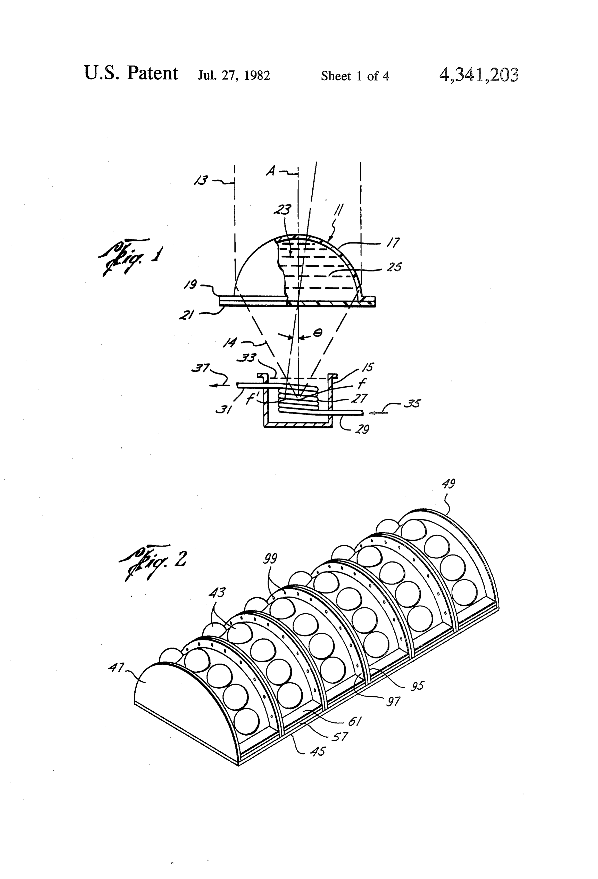
with the accompanying drawings, in which like parts O The energy of the sun's rays converged by lens 11 are given like reference numerals and wherein: into cup 15 may be used to heat coil 27 directly, by FIG. 1 is an elevation, partly in section and with some focusing the rays on the coil, or indirectly, by focusing parts broken away, illustrating the use of a liquid-filled the rays in the heat transfer liquid 33 surrounding the lens to heat by solar radiant energy a coil disposed in a coil. In the latter case, the liquid 33 conveys heatenergy liquid-filled cup; 15 to the coil 27. The coil 27 when heated directly or FIG. 2 is a pictorial view of a plurality of solar energy indirectly then conveys heat energy to the heat transfer collectors of the preferred embodiment of the present fluid indicated at 35, 37 flowing within the coil. The invention interconnected for use, for example, on the heated fluid within the coil may then be conveyed roof of a building; through output tube 31 to an immediate use, or to a FIG. 3 is an elevation, partly in section and with some 20 storage area for subsequent use.
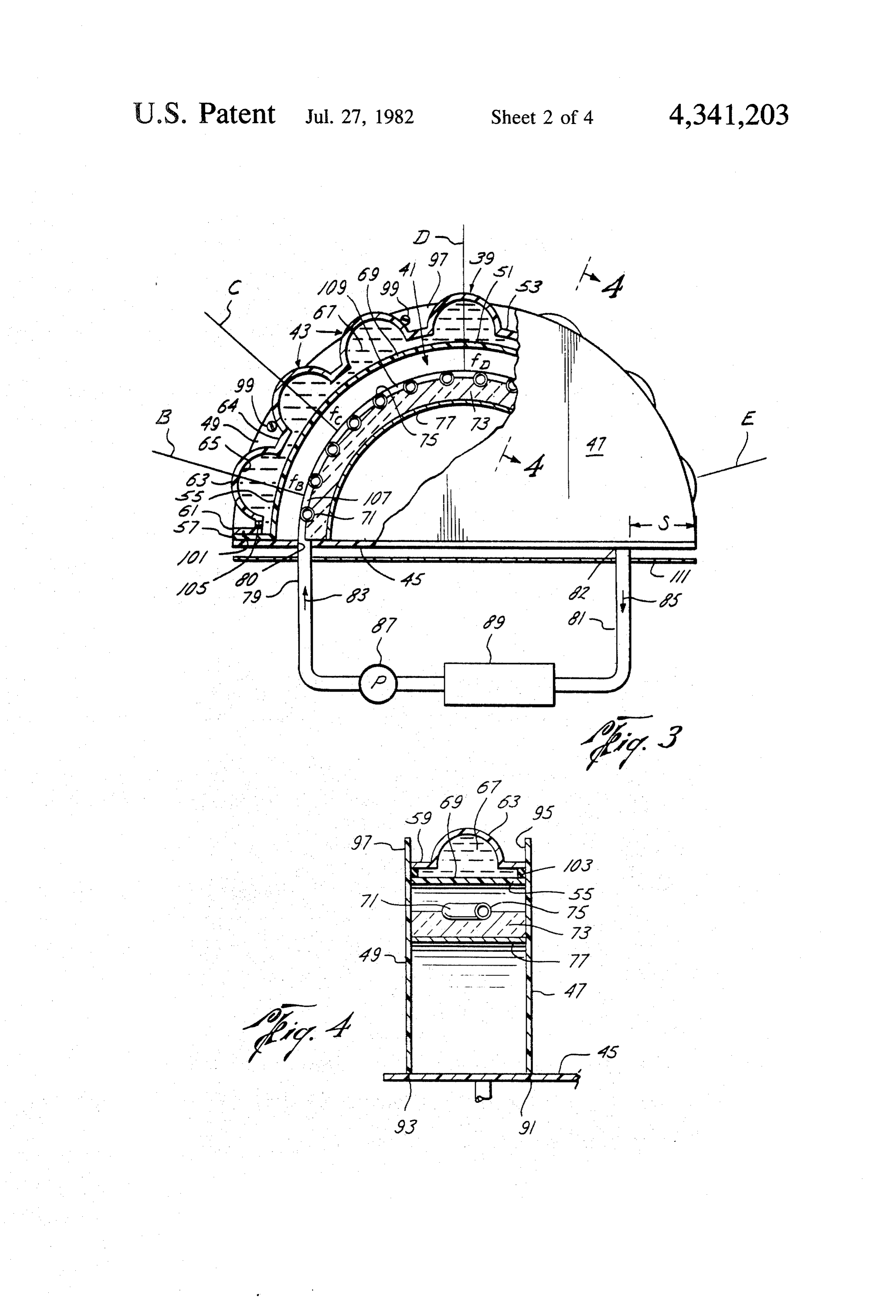
parts broken away, of the preferred embodiment of the Referring now to FIG. 3, there is shown a solar en solar energy collector of the invention; ergy collector including an energy concentrating unit, FIG. 4 is a section of the preferred embodiment of the indicated generally at 39, and an energy collecting unit, present invention as taken along section lines 4-4 of indicated generally at 4:... Energy concentrating unit 39 FIG. 3; 25 comprises a plurality of converging lenses 43 disposed FIG. 5 is an elevation, partly insection and with some in a curved, arch-like configuration over and spaced parts broken away, of an alternative embodiment of the apart from energy collecting unit 41. Unit 39 may, for solar energy collector of the invention; example, have the shape of a round arch. Collecting FIG. 6 is an elevation, partly insection and with some unit 41 is likewise disposed in a curved, arch-like config parts broken away, of another alternative embodiment 30 uration, which preferably conforms to the curvature of, of the solar energy collector of the invention; or is parallel to, the concentrating unit 39. A backplate FIG. 7 is a pictorial view of an alternative collecting 45 and sides plates 47, 49 are provided for supporting unit of the embodiment shown in FIG. 5; the concentrating unit 39 and the collecting unit 4 in FIG. 8 is a pictorial view of an alternative collecting fixed, preferably parallel uniformly spaced apart rela unit of the embodiment of FIG. 3; and 35 tionship with each other.
FIG. 9 is a pictorial view of a mold used to form the Concentrating unit 39 includes an inner strip 5 and lenses of the collecting unit of the preferred embodi an outer strip 53 of transparent thermoplastic such as, ment of the invention. for example, Lucite acrylic. Inner plastic strip 5 com DETAILED DESCRIPTION OF THE prises curved central body portion 55 and first out PREFERRED EMBODIMENT OF THE wardly extending flanged portions 57 at both ends of INVENTION the strip 51. Central body portion 55 is generally semi circular in curvature and has parallel sides, i.e., body
Referring to FIG. 1, converging lens 11 refracts the portion 55 is generally of the shape of a hollow, right sun's rays 13 impinging upon the lens 1 and the re circular semicylinder.
fracted rays 14 are converged into a cup 15. Lens 11 45 Outer plastic strip 53 comprises curved main body includes a transparent curved portion 17 that is gener section or portion 59 (FIG. 4), second outwardly ex ally of the shape of a hollow hemisphere with an out tending flanged portions 61 at both ends of the strip 53, wardly extending circumferential flange 19 disposed and a plurality of spherical bulges or bubbles 63 on main around its edge. Lens 11 also includes a transparent disk body section or portion 59. Spherical bulges or bubbles portion 21 of substantially the same diameter as the 50 63 form the outer surfaces of converging lenses 43. The outer diameter of flange 19. Disk portion 21 is attached area 64 of main body section 59 between and to the sides to curved portion 17 at flange 19. The chamber 23 be of bubbles 63 conforms generally to the shape of a hol tween lens portions 17, 21 is filled with a transparent low, right circular semicylinder in like manner as does liquid 25. central body portion 55 of inner plastic strip 51. The A helical coil 27 of hollow tubing is disposed in cup 55 inner 51 and outer 53 strips are parallel, the curved 5. The tubing forming coil 27 extends from the bottom portion 55 of inner strip 5; being nested within and and the top of the coil through the walls of the cup 15 uniformly spaced apart from the curved section 59 of to form input tube 29 and output tube 31. Cup 15 con outer strip 53. Flanges 61 of outer strip 53 rest upon tains a heat transfer liquid 33 which fills the cup to a flanges 57 of inner strip 51 and are attached thereto, as level above the top of coil 27. A heat transfer fluid, the by cement, thereby supporting outer strip 53 in fixed flow of which is indicated by arrows 35, 37, flows nesting relationship with inner strip 51. through the hollow tubing forming coil 27 and tubes 29, The space between the inner and outer strips, 51, 53, 3. The fluid indicated by 35, 37 may be either a liquid including the chambers between the inner surfaces 65 of or a gas. bubbles 63 and the curved portion 55 of inner strip 51, Parallel light rays impinging upon lens 11 will be 65 is preferably filled with a transparent liquid 67. A liquid converged at focal point fof the lens when such parallel having optical properties similar to those of the plastic rays are also parallel to the optical axis A of the lens. used for the strips 5,53 should be used. Also, liquid 67 Parallel light rays that impinge upon lens 11 at an angle should be substantially immune from deterioration 8 when exposed to the sun. Liquid 67 is preferably min strip 53 and backing strip 77, as by cement. Plates 47, 49 eral oil such as, for example, Nujol. There is fluid com extend upward from curved section 59 as at 95, 97 to munication between the liquid-filled chambers under provide flanges through which bolts 99 may be inserted the bubbles 63 through passageways 69 between and to for attaching a plurality of collectors together into a the sides of the bubbles. larger unit (FIG. 2).
Bubbles 63, the corresponding liquid-filled chambers Backplate 45 and side plates 47, 49 may be made of beneath the bubbles and the respective segments of any suitably rigid material such as, for example, wood, curved strip portion 55 thereunder comprise meniscus plastic or metal. It is preferred to use a transparent type converging lenses 43 of concentrating unit 39. thermoplastic such as that used for concentrating unit Although it is preferred to employ liquid-filled lenses, 10 39, e.g., Lucite acrylic.
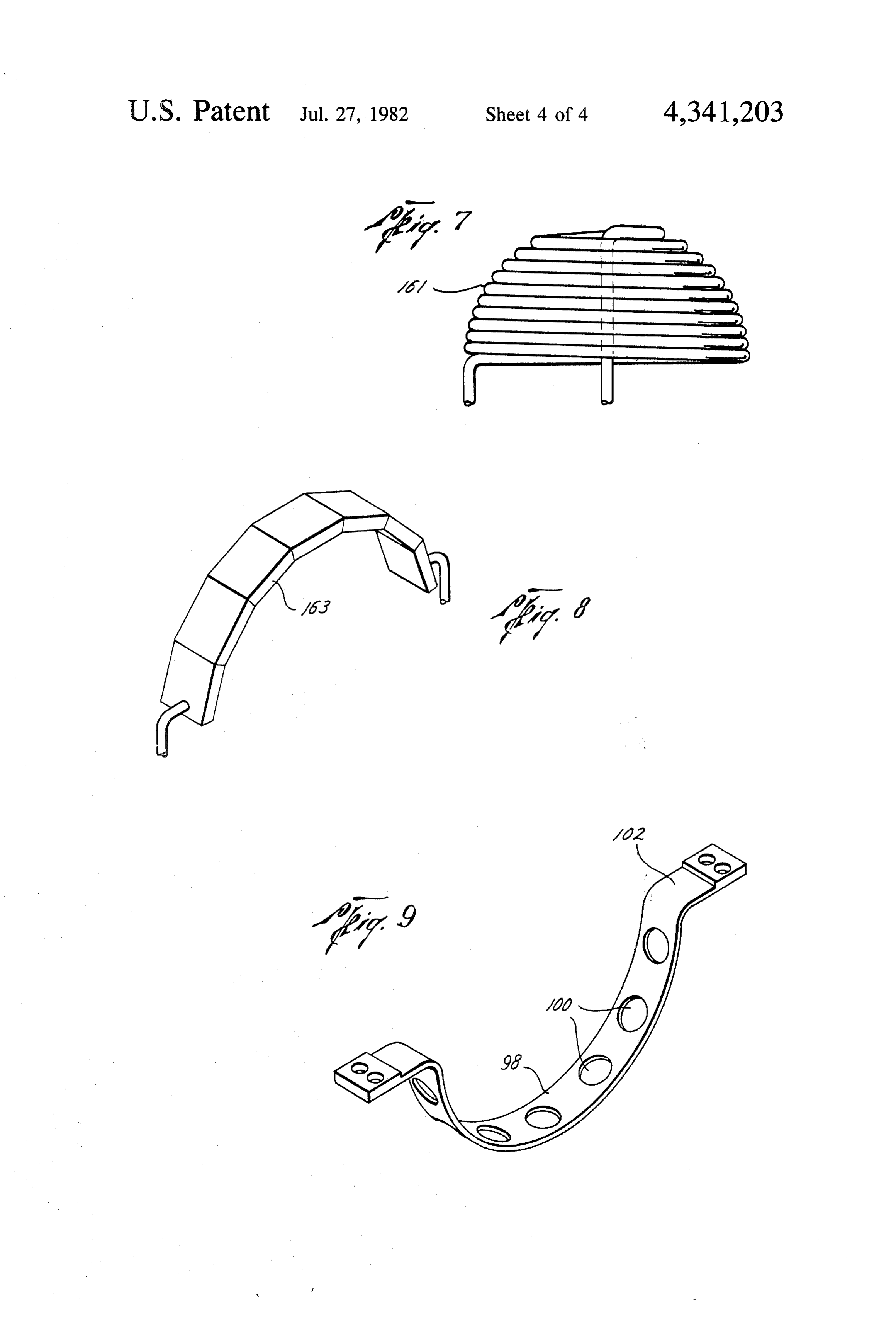
liquid 67 may be eliminated, in which case lenses 43 The plastic strips 51, 53 of energy concentrating unit would be hollow. Lenses 43 are preferably uniformly 39 may be manufactured quickly and inexpensively by a angularly spaced on unit 39 around its transverse axis or process known in the art as "blow-forming', wherein a its center of curvature. The number of lenses 43 that strip of sheet of plastic such as Lucite acrylic is warmed may be used depends, of course, upon the size of the 15 to a softened state at a temperature of 300 plus or minus lenses and the size of the unit 39. In a solar energy 30 F., is forced by air pressure into conformity with the collector of six feet in outside diameter, for example, inner surface of a rigid mold, and is then cooled and five to seven lenses often to twelve inch diameter may hardened. The mold for the outer strip 53 may have an be used. inner semicylindrical surface portion conforming in Collecting unit 41 comprises a serpentine coil 71 of 20 shape with the main body section 59, a plurality of tubing disposed in curved, arch-like configuration spherical recesses or depressions uniformly spaced under and uniformly spaced apart from or parallel to along the semicylindrical portion conforming in shape inner strip 51 of concentrating unit 39. Coil 71 may be with bubbles or bulges 63, and planar surfaces at the made of copper tubing of, for example, one-eighth inch ends of the semicylindrical portion conforming in shape to one quarter inch diameter. An insulative material 73 25 with flanged portions 61. The mold for the inner strip 51. such as, for example, fiberglass is disposed around the may have an inner semicylindrical surface portion con sides and the lower portion of the tubing for partially forming in shape with central body portion 55, and thermally insulating the coil 71, leaving an upper por planar surface portions at the ends of the semicylindri tion 75 of the tubing exposed to the lenses 43. A rigid cal portion conforming in shape with flanged portions backing strip 77 is disposed under the coil 71 for sup 30 57. Another mold that may be used to form outer strip porting the coil and the insulative material 73. Backing 53 is shown in FIG. 9 and has an inner semicylindrical strip 77 is attached at its ends to backplate 45, as by surface portion 98 conforming in shape with body sec cement. Backing strip 77 may be made of suitably rigid tion 59, a plurality of round holes 100 uniformly spaced metal or plastic or other materials. along the semicylindrical portion, and planar surfaces An input pipe 79 and an output pipe 81 extend 35 102 at the ends of the semicylindrical portion. When a through openings 80, 82, respectively, in backplate 45 softened plastic strip or sheet is placed in a mold, air and are connected to the ends of coil 71. Input pipe 79 pressure is applied to the interior of the mold so as to and output pipe 81 may be extensions of the tubing force the plastic against the inner surface of the mold forming coil 71, or they may be separate pipe joints into conforming contact therewith. When a mold such coupled to the coil. as that shown in FIG. 9 is used, the plastic is forced into A heat transfer fluid, the flow of which is indicated conformity with surfaces 98 and 102, and "pops' out by arrows 83, 85, is pumped by a pump 87 through input through holes 100, thus forming bubbles 63. When the pipe 79 to coil 71, through coil 71 and then away from plastic is then cooled and hardened, it may be removed coil 71 through output pipe 81. It will be appreciated, from the mold, retaining the shape of the inner surface however, that the direction of flow may be reversed if 45 of the mold.
desired, whereupon pipe 81 would serve as the input The plastic strips 51, 53 are attached together, as by pipe and pipe 79, the output pipe. The heat transfer fluid cement, at their ends at flanges 57, 61. A seal 01 of indicated by 83, 85 may be either a liquid or a gas. The rubber or the like is disposed between the flanges ex unit from which the fluid is pumped to coil 71 and to tending the width of the flanges in grooves cut in the which the fluid returns from the coil is indicated at 89. 50 adjoining surfaces of the flanges. Seal 101 prevents Unit 89 may be either a unit for immediate utilization of leakage of liquid 67 from between the flanges. the heat transfer fluid, such as a heater or an air condi Sealing strips 103 (FIG. 4) of rubber or the like are tioner, or a unit for storing the fluid for subsequent tightly wedged or sandwiched between the inner and utilization. outer plastic strips 51, 53 at the sides thereof to contain Flanges 57 of concentrating unit 39 are disposed upon 55 liquid 67 between the strips and to prevent leakage of the upper surface of backplate 45, unit 39 being sup liquid 67 from the sides of the plastic strips. When plas ported thereby. Flanges 57 may be affixed to backplate tic sttrips 51,53 are cemented together and seal 10, and 45, as by cement. Collecting unit 41 is also supported by sealing strips 103 are in place, a filling hole may be backplate 45, input and output pipes 79, 81 being pro drilled in the outer strip 53 in the main body section 59 vided a tight fit in openings 80, 82 or otherwise being thereof through which liquid 67 may be injected to fill secured within said openings, as by cement. the space between the strips, including the chambers Semicircular side plates 47, 49 provide additional under the bubbles 63. When the liquid 67 has been in rigidity and support for the elements of the solar energy jected so as to fill all the space between the strips, a collector of FIG. 3. Plates 47, 49 are attached at their rubber plug 105 is then wedged in the filling hole to seal straight edges 91, 93 (FIG.4) to backplate 45, as by 65 the hole and prevent leakage of liquid 67 therefroin. cement. Plates 47, 49 extend perpendicularly upward Lenses 43 may be of any size from, for example, ten from backplate 45 and are affixed to the side of curved inches to forty inches in diameter. For a typical home portion 55 of inner strip 5i, curved section 59 of outer installation for heating or air conditioning purposes, 9 five to seven lenses of from ten to twelve inches in fixed position such that lenses 43 are exposed to the sun diameter are preferred. A concentrating unit 39 of four during the day and such that the track of the sun will feet in diameter will accommodate five of such lenses, pass sequentially through, or near, each of the optical and a unit 39 of six feet in diameter will accommodate axes of the lenses 43, several of such optical axes being seven of such lenses. shown at B, C, D and E. For example, the collector can The lenses 43 are preferably meniscus-type converg be mounted on the roof of a house with its backplate ing spherical lenses, but other shapes of converging horizontally disposed and with the semicircular arc of lenses may be used such as, for example, plano-convex lenses oriented in a generally east-west direction. In this or biconvex spherical lenses, or aspherical lenses. The position, optical axis D of the topmost lens will be verti shape of the lenses 43 depends, of course, on the shape 10 cal, and the optical axes B, E of the lowermost lenses on of the mold used to blow-form the plastic strips or each side of the arc will be at a small angle, typically sheets 5E, 53 which form the surfaces of the lenses. If fifteen degrees or less, to the horizontal. Axis C of a lens the inner plastic strip 51 is formed with bubbles or adjacent the lowermost lens will be at an intermediate bulges thereon protruding inwardly toward collecting angle, such as forty degrees, to the horizontal, that is, unit 4R and corresponding to the bubbles 63 so that the 15 greater than such small angle but less than ninety de two sets of bubbles may be aligned, then lenses 43 grees, the value of such intermediate angle depending would be of the biconvex type. Alternatively, flat por on the size and number of lenses used and the spacing tions of sufficient size, e.g., squares with sides equal to between them.
the diameter of bubbles 63, may be provided on inner strips 51 in alignment with bubbles 63, thus forming 20 to The a collector is set up for use by connecting coil 71 usage system 89, such as a domestic absorption type plano-convex lenses. Other shapes of lenses may be air conditioning system, a heating system or a storage obtained by further varying the shape of the blow-form tank, through pipes 79, 81 and pump 87. A heat transfer ing molds. fluid, such as one of Monsanto Industrial Chemical Moreover, several types of converging lenses may be Co.'s Therminols, or Dow Chemical Co.'s Dowtherm, formed by providing the inner plastic strip 51 with the 25 is forced through coil 71 by pump 87. Such a heat trans bubbles 63 and providing the outer plastic strip 53 with fer fluid may be, for example, an alkylated benzene. The appropriate curved surfaces in alignement with the bubbles on the inner strip. For example, by providing particular fluid used will depend on the temperature ranges it will be subject to in operation. Therminol 66, inner strip 51 with a plurality of bubbles bulging inward for toward coil 7, plano-convex lenses may be formed by turesexample, range may be used where the operating tempera from 15 F. to 650 F., and Therminol 88 providing outer strip 53 with flat portions in alignment may be used for temperatures up to 750 F. Applicant with the bubbles; meniscus convex lenses may be has found that an installation such as shown in FIG. 1, formed by providing outer strips 53 with curved sur using Nujol inside the lens, may reach a temperature of faces in alignment with the bubbles and oriented toward coil 71; and biconvex lenses may be formed by provid 35 600At F.dawn, inside the cup.
the sun's rays will be directed in a generally ing outer strip 53 with curved surfaces in alignment horizontal direction toward one of the ends of the col with the bubbles and oriented away from coil 71. lector. Assuming for the purposes of this description Lenses 43 are disposed in concentrating unit 39 with their optical axes lying in a single plane. All the lenses that the easternmost lens is the one with axis B, the sun's 43 have the same focal length. Applicant has found that 40 rays will be at an angle of, for example, fifteen degrees a piano-convex lens such as lens it shown in FIG. , to axis B. The sun's rays will generally be concentrated made of acrylic plastic three sixteenths inches thick, by this easternmost lens to one side of focal point fB in filled with mineral oil and having a diameter of twelve the focal plane of such lens and will impinge upon coil inches and a depth of four inches, has a focal length of 71 near the portion 07 of the coil proximate the focal eight inches. Each of the lenses 43 is spaced from the 45 point fB. This will cause the portion 107 of the coil to be coil 7 a distance equal to its focal length, so that all the warmed slightly. This in turn will cause the heat trans foci of all the lenses 43 are on or near the coil 7. fer fluid being forced through coil 71 by pump 87 to be The solar energy collector of FIG.3 may be installed warmed. The actual amount of warming will depend to in any location providing exposure to the sun's rays, for a large extent on the optical characteristics of the lens, example, on the roof of a house or other building, or on 50 including its aperture.
the ground. Preferably, such a location should be ex At the same time, the sun's rays are at a larger angle, posed to the sun's rays from dawn until dusk, because for example, forty degrees, to the adjacent lens, i.e., that the greater the exposure time to the sun's rays, the more lens having optical axis C, so that the rays are generally solar energy will be collected by the invention. The concentrated farther to one side of the corresponding solar energy collector of FIG. 3 has its lenses disposed 55 focal point fo than is the case with the rays focused by generally in a semicircular arc and will be, therefore, the easternmost lens with respect to fp. Consequently, particularly effective when the collector is mounted the portion of the coil proximate fowill be warmed to a with its backplate horizontally disposed with respect to lesser extent than is coil portion 107, and the heat trans the ground and in a location having maximum exposure fer fluid will in turn be warmed to a lesser incremental time to the sun's rays. If a location having maximum extent. Now, the sun's rays are at an increasingly larger exposure time cannot be found in the vicinity in which angle to the axes of successive lenses so that the rays are the invention is to be used, then it may be desirable to concentrated at points increasingly farther from the use a concentrating unit having less than a complete respective focal points, resulting in diminishing warm semicircular arc of lenses, the shape of the arc to be used ing of the coil, for example at coil portion i09, and corresponding to that portion of a complete arc that 65 hence the fluid, with respect to successive lenses. would be exposed to the sun's rays. Because axis D is essentially normal to the sun's rays Operation of the preferred embodiment of the collec at dawn and axis E actually extends away from the sun, tor of the invention includes securing the collector in a very little, if any, warming of the coil and the fluid 10 therewithin will be accomplished by the corresponding such as Lucite acrylic plastic is used for backplate 45, a lenses, and those between such lenses, at this time. portion of the sun's rays will pass through collecting At some point in time after dawn, the sun's rays will unit 39 and backplate 45 at strips S and into the room or be positioned on or near axis B of the easternmost lens. building. A translucent, non-transparent panel 111 may At such time, the sun's rays will be focused at focal be disposed between the collector and the observer is point fB by such lens. On a clear day, i.e., when the sun's desired, for example, as a part of the ceiling of the room, rays are primarily direct as opposed to diffuse, the tem to allow light to pass into the room while partially perature at the focal point of a lens of the type described masking the collector apparatus from view. For exam above may be approximately 600 F. when the sun is ple, positioned on or near its optical axis. Thus, coil portion O 11i atodecorative provide or colorful panel may be used for panel aesthetically pleasing results. Such a 107 is heated extensively at fB, as is the heat transfer panel may instead be used for backplate 45 itself, fluid within the coil. Furthermore, the sun's rays are at thereby avoiding using both a backplate and a separate a smaller angle than at dawn to the adjacent and succes panel.
sive lenses, so that warming of the coil, and hence the fluid, by such adjacent and successive lenses is greater 15 of Ifa single energy usage demand is greater than the capacity than at dawn. As a result, fluid flowing through coil 71 be installedcollector, on the then a plurality of collectors may same roof and may be attached to is heated extensively at fB, and is heated further by the gether, for example, as shown in FIG. 2, to increase the adjacent and successive lenses in successively decreas total amount of solar energy collected. If a plurality of ing amounts. collectors are used, the coils of the individual collectors It will be appreciated that during the course of a day, 20 may be connected in series so that the heat transfer fluid the sun will be positioned on or near the axes of each lens successively, e.g., on axes C, D and E. At such therein flows from one collector to the next, or the coils times, the portions of the coil proximate the respective may be individually connected to a common source, focal points of the lenses, and hence the fluid within the suchcommon as a large storage tank, so the fluid flows from the source, to one of the coils, and then back to the coil, will be warmed extensively. At the same time, the 25 adjacent and successive lenses in both directions from common source. As shown in FIG. 2, adjacent collec the lens on whose axis the sun is positioned, i.e., in the tors are attached together by bolts 99 and nuts (not direction of the sun's apparent movement and in the shown) inserted through holes in extensions 95, 97 of opposite direction, will concentrate the sun's rays to a side plates 47, 49.
lesser degree and will warm the coil, and the fluid, in 30 Although the collector described above and shown in successively diminishing incremental amounts. FIGS. 3 and 4 is preferred, many variations in structure Furthermore, even when the sun is positioned be are possible.
tween and at an angle to the optical axes of two adjacent For example, the lenses may be disposed with their lenses, such as between axes B and C, the lenses corre axes in a plurality of planes rather than in a single plane sponding to such axes will concentrate the sun's rays in 35 as in the preferred embodiment. In such an alternative the manner previously described with respect to rays embodiment, the sun may be positioned on an optical arriving at an angle to an optical axis, and will warm the axis of a lens even if the sun passes over the collector at coil and fluid accordingly. In like manner, the lenses an angle to such a single plane. As a result, substantial adjacent to such two lenses in both directions, and the solar energy can be collected regardless of the season of lenses successive to them, will warm the coil and the the year.
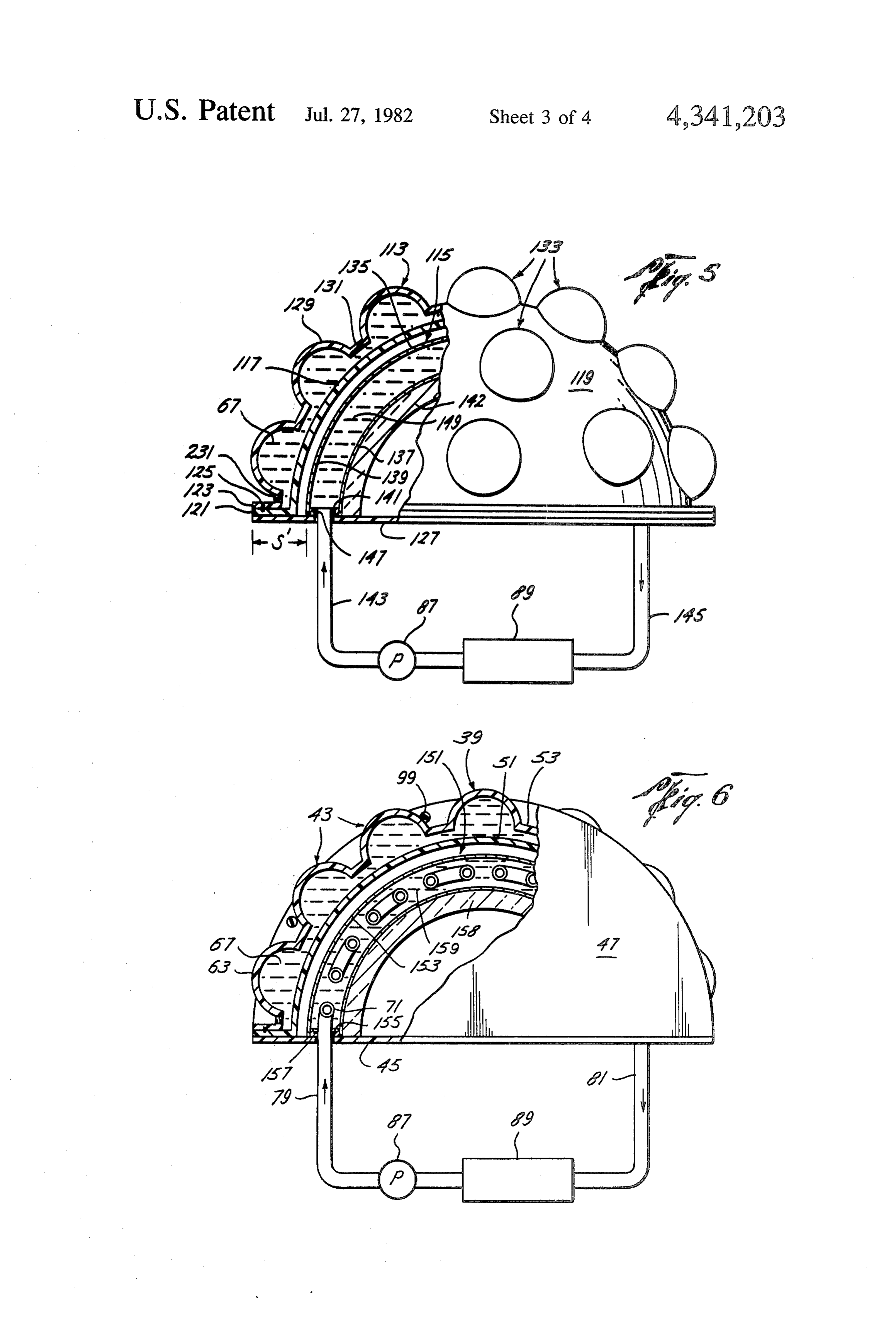
fluid in successively smaller increments. Thus, the alternative embodiment of the invention Thus, even though the collector has no moving parts, shown in FIG. S is especially suited for multi-season the sun's rays are collected continuously between sun use. In FIG. 5, there is shown a solar energy collector rise and sunset. The actual amount of solar energy col having a concentrating unit 113 and a collecting unit lected, of course, will vary during the course of a day 45 115. Concentrating unit 113 comprises inner and outer depending on the position of the sun relative to the transparent plastic domes 117, 119, respectively. Inner optical axes of the lenses, with the peak energy-collect dome 117 is nested within and spaced apart from outer ing periods occurring during those times when the sun dome 119. The domes 117, 119 may be made from Lu is positioned on or near one of the axes. cite acrylic plastic. The domes 117, 119 each have a As described above, the axes of the lenses are in a 50 body portion generally of hollow hemispherical config common plane. If the axis D of the topmost lens is verti uration, and have outwardly extending circumferential cal, then this common plane is vertical. When such flanges 121, 123, respectively, at their edges. The domes positioning will give best results for positions on the 117, 19 are attached together, as by cement, at the equator during an equinox, the results for other geo flanges 121, 123, the lower surface of flange 123 being graphical locations at other times of the year may not be 55 cemented to the upper surface of flange 121. A circular optimum. Therefore, it may be desirable to fix the posi seal 25 of rubber or other suitable material is sand tion of the collector so that the average results are opti wiched between flanges 121, 123 in opposing grooves mum over the course of a year. cut in the flanges so as to provide a fluid-tight sealed In addition to collecting solar energy for use in air connection between inner and outer domes 117, 119. conditioning and heating systems, the collector shown A circular disk or backing plate 127 is connected to in FIG.3 may serve as a skylight in allowing a portion the lower surface of flange 121, as by cement. Plate 127 of the sun's rays to be transmitted through the collector is preferably made from transparent plastic, such as and into the interior of the room or building on the roof Lucite acrylic.
of which it is installed. At both ends of the collector, The body portion of outer dome 119 includes a plu there is a strip indicated at S between the coil 71 and the 65 rality of hollow, outwardly protruding convex bulges collector ends that is unobstructed by the coil when or bubbles 129 uniformly disposed about its surface. viewed from below, for example, from the interior of Bubbles 129 are generally spherical in shape and are like such a room or building. Thus, if a transparent material previously described bubbles 63 shown in FIG. 3. The 11 spherical portion of dome 119 between bubbles 129 is Thus, in FIG. 6there is shown a solar energy collector indicated at 31. having a concentrating unit 39 of the preferred embodi The space between the inner and outer domes 117, ment and a modified collecting unit 151. Modified col 119, including the space between portion 131 and the lecting unit 51 includes an arched tube 153 of metal or inner dome and the space between the bubbles A29 and 5 other thermally conductive material, such as steel, sur the inner dome, is preferably filled with the transparent rounding the serpentine coil 71. The tube 153 has inserts liquid 67. Liquid 67 may be injected between the domes 155 attached to the tube just inside of its ends, as by through a hole drilled in the outer dome. A plug 231 of welding, for closing the tube. Inserts 155 have holes rubber or other suitable material is then wedged in the therein through which pipes 79, 8 extend for connec hole to seal it and prevent leakage of liquid 67 from the 10 tion to coil 7i. Seals 157 are provided around the pipes hole. 79, 81 where they pass through the holes in inserts 155 Inner and outer domes 17, 19 may be made by the to prevent fluid leakage from around the pipes. Ther blow-forming technique previously described, using mally insulative material A58 is provided under the tube appropriately shaped molds having either a smooth 53.
inner surface in the case of inner dome i7, or a plural 15 The tube 53 is filled with a heat transfer fluid 59, ity of spherical depressions in an otherwise smooth such as Therminol or Dowtherm, which may be in inner surface in the case of outer done 19. jected into the tube through a hole in the tube, which is The bubbles 29, liquid 67 thereunder and the respec then plugged or sealed. Additional heat transfer fluid, tive adjacent surfaces of inner dome i7 comprise a such as Therminol or Dowtherm, is pumped through plurality of meniscus-type convex lenses 133 like previ 20 coil 71 by pump 87.
ously described lenses 43, shown in FIG. 3. Lenses 33 in operation, the lenses 43 concentrate the sun's rays are all of the same focallength and are uniformly spaced onto tube 53, which is warmed thereby. The fluid from collecting unit 15 at a distance such that the focal within the tube and in contact therewith is warmed by point of each lens is on or near the collecting unit 15. conduction of heat from the walls of the tube to the Collecting unit 115 comprises a bouble-walled dome 25 fluid. This fluid then helps distribute the heat through 35 of metal or other thermally conductive material out the tube, and also to coil 7, by convection and such as, for example, steel. Dome 135 is of generally conduction. Since the fluid is in surrounding relation to hemispherical configuration and includes an inner wall the coil 71, the heat is more uniformly imparted to coil 837 and an outer wall 139 spaced therefrom. An annular 71 and, hence, to the additional fluid being pumped member 141 is disposed between the inner and outer 30 therewithin.
walls adjacent to their edges and is connected to each In another alternative embodiment of the invention, wall, as by welding. A layer of thermally insulative the double-walled dome 35 of the collecting unit material 142 is provided under inner dome wall 137. shown in FIG. 5 may be replaced by a coil 161 of cop An input pipe 143 and an output pipe 145 are inserted per tubing similar to coil 71 and shown in FIG. 7, only through holes in diametrically opposed sides of annular 35 convoluted to conform generally to hollow hemispheri member 4a and placed in communication with the cal configuration.
space between the inner and outer walls 37, 39. An In another alternative embodiment of the invention, 0-ring seal 47 of rubber or the like is disposed in a the arched coil 7 of FIG.3 may be replaced by a plu groove in member 41 around each pipe to prevent fluid rality of flat, hollow plates 63 as shown in FIG. 8, leakage from around the pipes. connected together and forming an arch under the in use, the collector is mounted so as to be exposed to lenses. Preferably, an equal number of plates 63 as the sun, as on a roof of a house. Since the lenses 33 are lenses are provided, each plate being aligned with and disposed with their optical axes directed from a spheri spaced from one of the lenses a distance equal to its cal surface in a plurality of planes, the sun will be on or focal length. A number of such plates 163 may be near one of the axes regardless of the position of the sun 45 welded together into an arch, for example, or one large in the sky, whether summer or winter, spring or fall. plate may be bent or crimped into the proper shape. The sun's rays will be concentrated by lenses 33 onto In another alternative embodiment of the invention, the outer surface of dome 35, which will be warmed in place of a spherical or arched coil or a double-walled thereby. dome the collecting unit may include a flat coil or a A heat transfer fluid 149 such as, for example, Ther 50 single flat hollow plate horizontally disposed with re minol or Dowtherm, is forced by pump 87 through pipe spect to the concentrating unit. In this case it is still 143 into the space between the dome walls. The fluid preferred that the foci of the lenses are all on or near the i49 circulates through the dome and collects the heat collecting unit, so lenses of different focal lengths from the dome walls and then exits from the dome should be used.
through output pipe 45, whereupon it flows to utiliza 55 The above alternative embodiments are merely exem tion system 89. In system 89, the solar energy collected plary of the possible changes or variations that may be by the fluid is either utilized immediately or stored for made.
later use. Upon the solar energy being spent, the fluid Because many varying and different embodiments 49 is pumped back to the dome 135 to collect more may be made within the scope of the inventive concept Solar energy. 60 herein taught, and because many modifications may be It will be noted that in the alternative embodiment of made in the embodiments herein detailed, it should be the invention shown in FIG. 5, the portion S' of the understood that the details described herein are to be collector that is unobstructed by the dome 35 when interpreted as illustrative and not in a limiting sense. viewed from below, thus serving as the skylight portion What is claimed as invention is: of the collector, will appear to an observer as an annular 65 1. A solar energy collector, comprising: ring. concentrating means for concentrating solar radiation The collecting unit of the preferred embodiment of including a plurality of converging lenses each the invention may also be modified in various respects. having a curved surface, an optical axis, a principal 12 focus and a focal length, said concentrating means body portion exclusive of said bubbles conforming including a first member and a second member of generally to the shapes of hollow hemispheres, said transparent thermoplastic, said first and second inner dome body portion being nested within said members each having a body portion, said body outer dome body portion.
portions being disposed in nested, spaced apart 5 2. Collector according to claim 1, wherein said pe interrelationship, one of said body portions of said ripheral portions of said domes include an outwardly members having a plurality of spaced apart hollow extending circumferential flange around the edge of hemispherical bubbles bulging away from the other each hemispherical body portion, said flanges each of said body portions and forming said curved having an upper and a lower face, said flanges being surfaces of said lenses, said bubbles being integral 10 interconnected, and having such lower face of said with and part of said one of said body portions of flange around said body portion of said outer dome said members, the interior surface of each of said adjoining such upper face of said flange around said bubbles defining a chamber, and each of said cham body portion of said inner dome.
bers being in communication with the space be 3. Collector according to claim 2, wherein said con tween said body portions of said members; 15 centrating means includes means for sealing the connec means for collecting solar radiation including a fluid tion between said flanges against fluid leakage, said transporting heat transfer unit; and sealing means including an annular rubber ring disposed frame means connected to said concentrating means between said flanges in opposing circular grooves cut in and said collecting means for fixing the position of such adjoining faces of said flanges. each of said lenses relative to said heat transfer unit 20 4. Collector according to claim 3, wherein said frame at a distance from said heat transfer unit substan means includes a rigid, flat circular disc connected to tially equal to its focal length so that said focus of such lower face of said flange around said body portion each of said lenses is located proximate said heat of said inner dome and supporting said inner and outer transfer unit, wherein said first and second mem domes.
bers each include a peripheral portion connected to 25 5. Collector according to claim 1, wherein said lenses and extending from said body portion for intercon all have the same focal length and said heat transfer unit necting said first and second members, said first includes a double-walled dome disposed under and and second members being an inner and an outer concentric with said inner dome body portion, said hollow dome, respectively, said bubbles forming double-walled dome being spaced from said lenses a said curved surfaces of said lenses being uniformly 30 distance substantially equal to said focal length of said spaced on said body portion of said outer dome, lenses.
said inner dome body portion and said outer dome
Page 13scan →
United states patent and trademark office
Certificate of correction
NVENTOR(S) : Dan E. Bloxsom it is certified that error appears in the above-identified patent and that said Letters Patent is hereby Corrected as shown below: Column l, line 64; change "transpartent" to -- transparent -- .
Column 6 line 57; change "sttrips"
Column 7 line 27; change "alignement" to -- alignment --.
Column 9 line 52; delete "When" and insert -- While -- .
Column ill, line l3; change "previously" to -- previously --.
signed and sealed this
Twenty-first D ay of September 1982
Seal
Attest
Gerald j. mossinghoff
Attesting Officer commissioner of Patents and Trademarks
Provenance
- Collection
- Patents citing this work
- Pages
- 13
- Method
- pdftotext (the PDF's own text layer) + pdftoppm 300dpi page scans
- Patent office record
- patents.google.com →
- Source
- Google Patents citing-documents table
- Assignee
- Bloxsom Dan E
- Published
- 1982-07-27
- Transcribed from
- patentimages.storage.googleapis.com →