

patent · US4176655A
Solar energy collection system and apparatus for same utilizing latent energy storage fluid
4 December 1979
Text
Page 1bibliographic recordscan →
United States Patent (19)
Levy
54). SOLAR ENERGY COLLECTION SYSTEM
AND APPARATUS FOR SAME UTILIZING
LATENTENERGY STORAGE FLUID
76 Inventor: Sidney Levy, 145 W. Cuthbert Blvd.,
Int. Cl? .......................... F24J 3/02; C09K 3/18;
52 U.S. C. .................................... 126/436; 126/400;
3,915,148 10/1975 Fletcher et al. ..................... 126/27 3,952,519 4/1976 Watson ................................ 126/400 3,957,030 5/1976 Davis ................................... 126/270 3,960,205 6/1976 Laing ..... ... 126/400 4,047,518 9/1977 Anderson ... ... 126/271 4,050,503 9/1977 Buckley ................................. 165/32 4,056,094 11/1977 Rosenbuerg ......................... 26/271 4,063,546 12/1977 Schmid et al. ....................... 126/27 4,100,091 7/1978 Powell ................................. 126/400 4,111,189 9/1978 Dizon ................................... 126/400
OTHER PUBLICATIONS
Kaelble et al., "Crystalline Polymers as Heat Storage Materials. In Passive Thermal Protection Systems',
Polymer Engineering and Science, vol. 15, No. 9, Sep. 1975, pp. 673–678. .
Primary Examiner-Samuel Scott
Assistant Examiner-Larry Jones
A solar energy collection and utilization storage system is constructed by using a lenticulated transparent ele ment closed at the back to form channels which are used to carry an energy storage fluid. The lenticulations are designed as light trapping surfaces so that virtually all of the energy from the sun at any time of day falling on the sheet is trapped by the lenticulations and trans ferred to an energy storage fluid which is in the pas sages formed by the lenticulations and the back cover panel. The rate of flow through the solar collector panel is controlled by a thermostatic valve element which opens the flow when the fluid reaches a predetermined temperature. The energy storage fluid is a dispersion of a crystalline polymer in a heat transfer fluid which has the capacity of storing heat by a latent heat of crystalli zation as well as by sensible heat. By use of a suitable polymer the energy storage fluid can store energy at a high enough temperature to produce a significant amount of shaft power utilizing a heat engine. The re mainder of the system comprises a storage container, suitable fluid connecting lines, a heat exchanger to ex tract sensible heat, and means to circulate the fluid through the system.
The combination of the flat panel collector and the efficient energy storage fluid combine to make an effec tive collector system which can be employed to drive a heat pump for heating and cooling or to generate elec tric power.
19 Claims, 7 Drawing Figures
Drawings
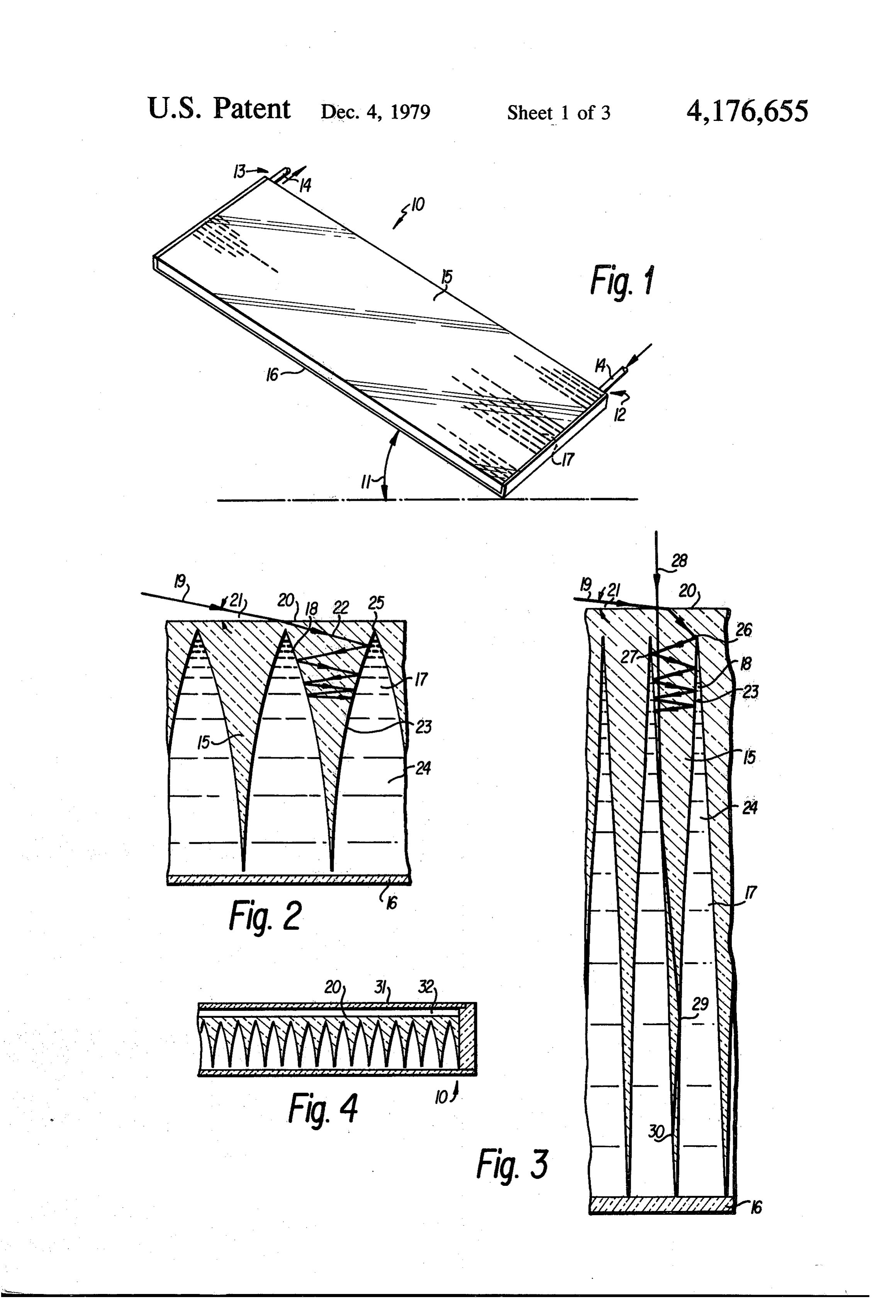
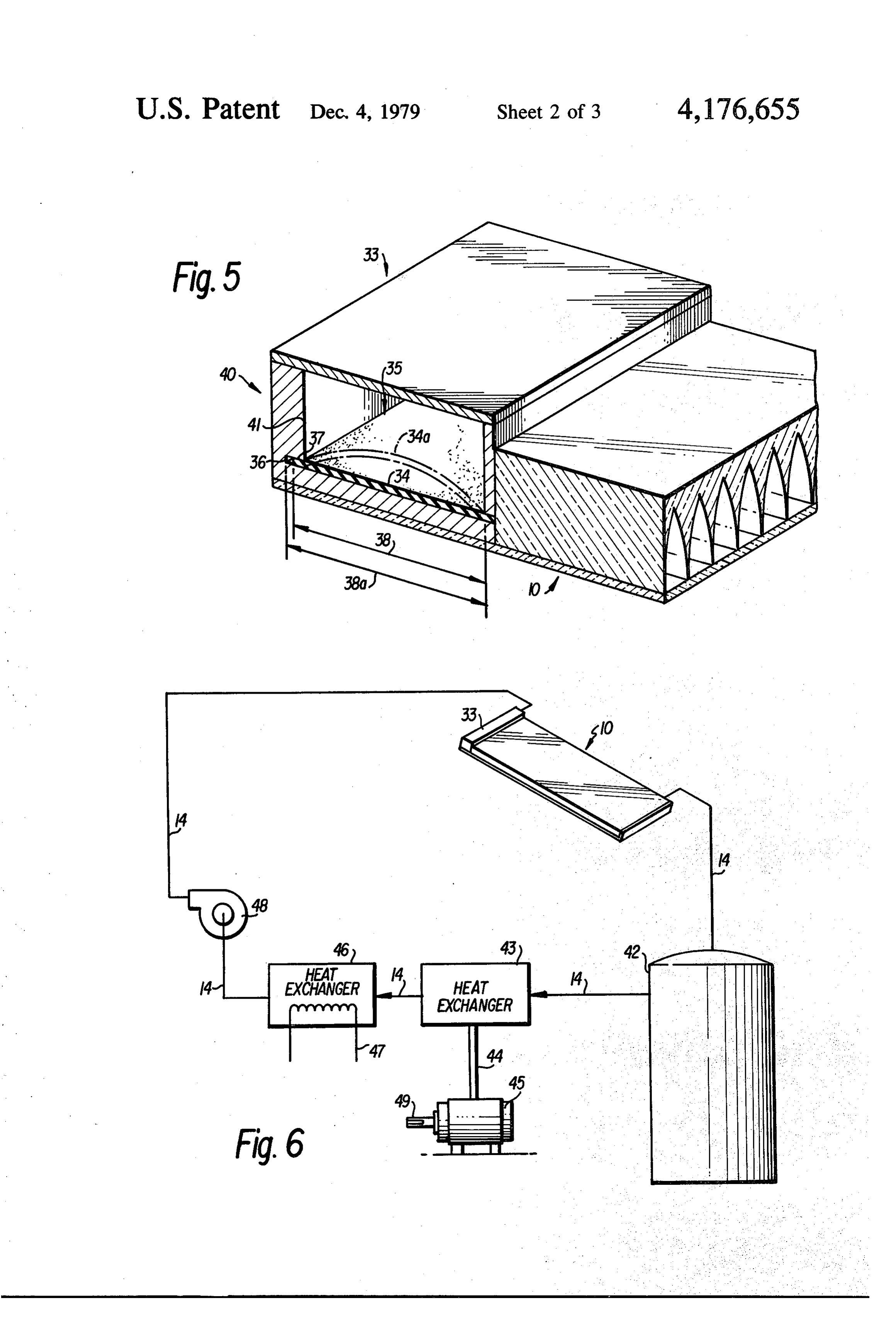
FIG. 1 is schematic of a solar collector receive the sun's radiation and cover of the collector panel or they are optical concen 10 shown tration systems which use lens or mirror optics to con moval ofwith attachments for the introduction and re the solar collector working fluid.
Page 2drawing sheetscan →
Page 3drawing sheetscan →
Page 4scan →
Table 1. Summary of Phase Change Material Properties
Product Ta' Am" Density, Therma
Polymer Supplier designation 'C F callgm btub gmcc cond. Linear polyethylene Philips Petroleum Mariex 6050 132 270 44.0 79.2 94 to .96 1 to 12.4 Bartlesville, Okla. 74003
Res. & Dev. Dept.
Isotactic polypropylene AviSun Co. Gen. purpose 1016 166 338 16.0 28.8 90 to .92 2.8
Polymethylene oxide Dupont Delrin 100 series l8l 358 38.0 68.4 1.42. 5.5
Plastics Dept.
Polyethylene oxide Union Carbide Corp. Polyox WSRN10 57 35 22.6 40.7 1.15-126 Chemicals & Plastics 270 Park Ave.
Poly E-caprolactam BASF-Color & Chem. Co., ULTRAMD-B6 ----degrades---- 1.4 5,85 (Nylon 6) 866 Third Ave. (10.70% cryst.)
Polyhexamethylene BASF ULRAMD-AK3 - - - - degrades - - - - 1,13 5,85
(Nylon 66)
Trans-polyisoprene Polymer Corp. Ltd. TRANS-PP conditioned: 23°C Sarnia, Ontario 35 95 6.65 12.0 - P -60°C 52 125.6 8.18 14.7 un us
Thermal conductivity, 10-6 cal/sec/sq cm/1(c/cm).
Page 5scan →
SOLAR ENERGY COLLECTION SYSTEM AND BRIEF DESCRIPTION OF THE DRAWINGS APPARATUS FOR SAME UTILIZING LATENT With the above advantages and with other features as ENERGY STORAGE FLUID will be hereinafter described, this invention comprises the devices, materials, constructions, combinations, and
BACKGROUND OF THE INVENTION arrangements of parts shown by way of example and Solar energy collector systems are generally one of illustrated in the accompanying drawings of a preferred two types. They are flat panel collector systems using a embodiment in which:
radiant energy absorbing fluid behind the transparent panel positioned to representation
FIG. 1 is schematic of a solar collector receive the sun's radiation and cover of the collector panel or they are optical concen 10 shown tration systems which use lens or mirror optics to con moval ofwith attachments for the introduction and re the solar collector working fluid.
centrate the incident radiation on to a smaller area col FIG. 2 is an enlargement of a small portion of the lector tube or other absorber which contains the work collector panel in section which illustrates the lenticular ing energy absorbing fluid. In general the flat panel 15 structure of the transparent cover section, and which collectors are much less costly to manufacture and they shows in general do not require tracking of the sun for good efficiency. face the track of light incident on the sur They generally do not provide high fluid temperatures the incident light isseveral of the panel at angles. The manner in which and are not suitable for generation of shaft power. The by the working fluidtrapped in the panel and absorbed shown in optical concentrator type of solar collector is usually 20 FIG. 3 where a low angle incident ray and a high fairly expensive to manufacture as compared with the angle incident ray are traced into the lenticulated flat panel and, for good efficiency, should be tracked to struction of the transparent cover section to showcon the follow the sun. The tracking system adds to the cost and manner in which the radiation is trapped and trans complexity of the system and reduces the reliability.
The optical concentrator units do have the advantage 25 ferred radiant to the working fluid by multiple reflection of the energy from the interface between the transpar that they do generate temperatures and are capable of ent cover section and the working fluid. heating the collector fluid to temperatures which are FIG. 4 is a schematic of a somewhat different em capable of generating substantial amounts of shaft bodiment of the invention where the cover section is power.
The present invention deals with a collector panel 30 supplied with a secondary transparent cover sheet to provide thermal insulation against convection cooling which combines the best features of the two types de of the panel.
scribed and which is capable of producing working FIG. 5 is a diagrammatic representation of a ther fluid temperatures high enough to generate shaft power. By the use of a novel working fluid composition poratedresponsive mally valving element which may be incor a large amount of energy can be stored per unit of mass 35 working fluid throughtothecontrol into the panel panel.
the rate of flow of the by a latent heat mechanism and released isothermally at an elevated temperature which provides for efficient theFIG. 6 is a schematic of a complete system utilizing elements of the present invention. The solar collec energy release to generate shaft work in a heat engine. tor panel is shown connected with a fluid storage reser SUMMARY OF THE INVENTION voir, a heat engine capable of extracting shaft power from the working fluid, means for extracting sensible
Accordingly, it is an object of the present invention heat to provide a solar energy collection system of novel the fluid from the working fluid and means for circulating through the entire system.
design which utilizes simplified construction and effi FIG. 7 is a table of a number of polymers usable on cient collection of incident solar radiation with high the system of the present invention.
It is another object of the present invention to pro DESCRIPTION OF THE PREFERRED vide a flat panel collector which is less costly to manu EMBODIMENT facture. Referring now to the figures, wherein indentical or It is a further object of this invention to provide a similar parts are designated by the same reference nu solar collector panel with a lenticulated construction 50 meral throughout and referring first to FIG. 1, the ref. which is capable of trapping all of the incident solar erence numeral 10 refers to a solar collector panel made radiation. ; in accordance with the present invention. It is a still further object of this invention to provide The solar collector panel comprises a cover of a a lenticulated construction solar collector panel which transparent material such as plastic or glass which has is capable of collecting the incident radiation at virtu 55 its surface formed into suitable lenticulations for the ally any angle without the necessity of tracking the sun. purpose of the invention. The collector is shown flat It is yet another object of the present invention to and this is the preferred shape although it may be provide a solar collector fluid to be used in conjunction curved for a particular situation without departing from with the flat panel collectors which is capable of storing the concept of the instant invention. large amounts of energy by a latent heat storage mecha 60 The panel is preferably disposed at a suitable angle to nism that can be isothermally released at an elevated the ground 11 which is such that the incident solar temperature. radiation will strike perpendicularly at the time of the It is a final object of the present invention to provide equinox. The angle is in fact the same as the latitude a solar energy collector system which is capable of where the panel is used. The panel is equipped with storing solar energy at a sufficiently high temperature 65 suitable means for conveying a working fluid into the that the system is capable of producing shaft work when panel 12 and out of the panel after exposure to the sun the working fluid is used in conjunction with a suitable light 13. These means will usually be a suitable form of heat engine. . . . . . . .", s pipe or tubing 14 which will be insulated to prevent 6 entry or egress of heat and which will be of a material operating temperature. Above this temperature the and size suitable for handling the working fluid in the continued expansion of the membrane. 34 causes it to quantities and at the temperatures attained. assume the alternative shape 34a by the buckling effect The panel 10 comprises a front section 15 containing caused by the attempt to confine the increased length the lenticulated pattern and a back section 16 which 5 38a in the length 40. The passage is opened and the rate closes off the sheet to provide channels 17 through of flow of the fluid is substantially increased. Since this which the working fluid is carried. These are more reduces the time the working fluid is in the solar collec clearly shown in FIG. 2. The form of the lenticulations tor panel 10, it will result in reducing the exit tempera 18 is shown in FIG. 2. The path of an incident light ture of the fluid. The membrane 34 will adjust to an beam 19 is shown as it strikes the surface 20 at a low 10 equilibrium position that will maintain the flow at a angle 21. The multiple reflection of the ray trace path 22 level to maintain a uniform exit temperature for the is shown as it enters the lenticulation 18 and is trapped working fluid.
in the material by the multiple reflection from the inter FIG. 6 is a schematic representation of a solar energy face 23 between the lenticulations 18 and the fluid 24. collection and utilization system using the instant inven The shape of the lenticulations 18 is a smooth curve 15 tion. The solar collector panel 10 is connected through which may be a circular or conic section with two the valving element 33 to a storage reservoir 42 by symmetric elements that intersect in a sharp angle at 25. means of the piping 14. The storage reservoir is of suffi It has been determined that this angle should be of the cient size so that it can contain enough of the working order of 5 in order to trap light that approaches the fluid to act as a reserve to supply energy for night time panel at an angle of 10 from the horizontal which in 20 use as well as for the extended periods when the sun most circumstances is the lowest angle that sunlight can light is not at peak. The reservoir is insulated thermally impinge on the collector panel. By reference to FIG. 3 from the environment to prevent heat losses. Working it can be seen how the entering light is trapped in the fluid is drawn from the reservoir 42 and is fed to the panel. The low angle light beam 19 is shown entering heat exchanger 43 where the sensible heat is used to the surface 20 at the low angle 21. The beam is refracted 25 drive a heat engine 45. This can be a standard steam so that it strikes the lenticulation 18 at 26. It is then turbine or engine, a vapor engine using another lower reflected from the interface 23 to the other side of the boiling fluid such as one of the fluorocarbons, or even lenticulation at 27. This is repeated a number of times an air system unit such as a Stirling engine. The shaft and as a result of the curve of the lenticulation, the power generated at 49 can be used in a variety of ways. angles of the reflections come closer to perpendicular. 30 It can be used to drive a heat pump for heating and The multiple reflections transfer all of the incident radi cooling a building. The power can be used to generate ation across the interface 23 to the working fluid 24. A electricity which may be directly used or stored. It can high angle ray 28 enters the transparent lenticulated also be used to drive the pump 48 which would provide member 15, is reflected at 29, and then subsequently at for forced circulation of the working fluid through the 30, and is trapped at the bottom of the lenticulation 18 35 system. The working fluid can also be piped by means and the energy is totally absorbed. of the lines 14 to a heat exchanger 46 which will with In many cases the solar collector panel will be used in draw sensible heat by means of the extraction element an exposed situation where there will be wind and rain 47. This heat can be utilized to heat a building, heat conditions. To minimize the convection loss of heat water for general washing use, or be used as heat in an from the panel, it can be modified as shown in FIG. 4. absorbtion cooling air conditioning system. Preferably The basic collector panel 10 has attached to the absorb this heat exchanger uses the fluid exhausted from the ing surface 20 a spaced transparent sheet 31 which heat engine system which has already extracted most ot forms a dead airspace 32 between the surface 20 and the the FREE ENERGY of the working fluid. After leav cover sheet 31 that insulates the collector thermally ing the heat exchanger 46 the fluid is conveyed by from the effects of environmental convection heat loss. 45 means of the lines 14 to a pump 48 previously noted. The flow of the working fluid through the solar col The pump 48 is an optional element in the system to be lector unit should be controlled so that the exit tempera used for the forced circulation of the working fluid ture is sufficiently high to have a high level of energy through the system. In most cases the thermal gradient storage in the fluid. The means which seems best suited in the solar collector panel should provide a sufficient to this purpose is a thermostatic valve of some type 50 drive to circulate the working fluid through the system. which is responsive to the temperature of the fluid. The working fluid is a material which comprises a While more complex systems can be used, it is one of dispersion of a polymer in a suitable liquid carrier. The the features of this invention that it uses a simple built in polymers that are used are those which are crystalline thermal sensing element that senses the temperature of over certain temperature ranges, examples of which are the working fluid at the exit point from the panel and 55 polyethylene and polypropylene. A table of a number of restricts the flow when it is too low and increases the polymers which are usuable in the system is given in flow when the temperature is at the desired level. This FIG. 7. In the case of polyethylene and polypropylene, valve arrangement is shown schematically in FIG. 5. a suitable liquid carrier could be ethylene glycol or The valving element 33 is shown attached as a header to propylene glycol which are commonly available liquids the solar collector panel 10. The exiting fluid from the 60 used for heat exchange fluids in a variety of applications panel passes between the membrane 34,34a and the wall including automobile engines. These liquids have high of the valve section 35. The membrane is in the re boiling points, 198 C. for ethylene glycol and 213 C. stricted position as 34 and in the open position as 34a. for propylene glycol, and they are mutually soluble The membrane is a material which expands when with water. They have high specific heats in the range heated. It fits into the space 36 and has on it a detent 65 of 0.6 for the operating temperatures used in the solar element 37. The dimension 38 of the membrane and of collector and, by mixing with water to bring the boiling the header 40 are made such that the membrane detent point down to slightly over the normal operating tem strikes the wall 41 when the fluid reaches the desired peratures, the specific heat of the solutions will be in the 7 range of 0.8. This makes the solutions efficient heat has good weathering properties. These materials can be storage media even without considering the effects. fabricated into the lenticulated form by extrusion, cast produced by the latent heat storage mechanism of the ing, press molding or similar processes. For higher tem polymer in the dispersion. perature systems glasses of various types would be em The specific example we will examine is the use of a ployed and these can be fabricated into the suitable high density polyethylene material Marlex 6050 dis structures persed in a 50% solution of ethylene glycol-water. The methods. Inbythe pressing or grinding or other well known case of the plastics panel members they specific heat of the solution is 0.8 in the range of interest are such that they would easily resist abuse in handling. and the boiling point is in excess of 150° C. The HD polyethylene has a crystalline melting temperature of 10 and The glass structures would be somewhat more fragile would require careful handling and design of the 132C. and a heat of fusion by crystalline melting of the polymer of 44 calories per gram. The dispersion with up assembly.
to 60% by weight of the polymer dispersed in the solu In reference to the orientation of the collector panel tion is still a relatively low viscosity fluid easily capable with respect to the sun, it should be noted that the ar of flowing through the collector unit. It should be 15 rangement suggested is only indicated as the most effi pointed out that the crystalline melting of the polymer cient one. By the nature of the light trapping lenticula does not involve an actual change of phase to a liquid. tions light which enters the sheet at an angle to the axis The material merely undergoes a change from a crystal is even more effectively trapped than the perpendicular line polymer to an amorphous material. As a conse rays since the angular approach causes the rays to inter quence the solid in liquid dispersion is not affected by 20 sect the wall at an effectively larger angle which will the change.
Advantageously the polymer has dispersed therein a If increase the penetration of the ray into the lenticulation. carbon black material which will make it an efficient the panel is tilted transversely it will not be as effi cient light and radiant energy absorber. This is done by meth ning rays, at catching either the early morning or late eve ods well known in the prior art. The polymer is then 25 relatively but since these rays are low angle ones with low energy content the full day efficiency dispersed into the glycol-water solution with the aid of will not be impaired materially. a suitable dispersing agent, e.g. glycerol triricomoleate 1%, and the use of intensive shear mixing as is done by Numerous alternatives of the collector system and a Charlotte or other colloid mill. The resulting disper collector panel as well as the working fluid will suggest sion is the working fluid which is advantageously used 30 themselves to those skilled in the art. However, it is to in the instant invention. The thermal properties of the be understood that the present disclosure relates to a fluid are as follows: preferred embodiment of the invention which is for Specific heat is the weight average for polyethylene purposes of illustration only and it is not to be construed 0.55 and the ethylene glycol-water solution 0.8 which as a limitation of the invention.
gives . . . 0.65 What is claimed is:
The latent heat storage at 60% polymer dispersion . . . 35 1. A solar energy collector system comprising a len 26.5 cal/gm ticulated collector, and substitute-an energy storage Boiling point . . . ca 150 C. fluid comprising a dispersion of a crystalline polymer in As a result, if the fluid exits from the solar collector a carrier fluid means for controllably circulating said panel at 135° C., it will have a heat content of energy storing fluid through said lenticulated collector (135'-20 C)x0.65+26.5=101.25 cal/gm panel and thence on to a heat engine and a heat ex of which 26.5 cal/gm are releasable at 132 C. which changer whereby the energy collected in said energy can be used to operate the heat engine. For example, the storage fluid is converted to useful shaft work and also use of water as the fluid for the heat engine will make exchanged with other fluids for heating. steam at a pressure of 27 psi. Utilizing other heat engine 45 2. A solar collector panel as described in claim 1 fluids would be equivalent to the relative increase over comprising a transparent member with lenticulations the boiling points. running the length of the member, a closing member on If the primary purpose of the solar collector is to the back of said lenticulated member, means for intro generate large amounts of shaft power efficiently, it is ducing said energy storage fluid into the spaces between obvious that other combinations can be utilized. 50 the longitudinal lenticulations at one of the ends of said
For example, from the table Delrin 100 has a crystal collector panel, and means for controllably removing line melting temperature of 181 C. and it could be used said energy storage fluid from the other end of said solar in conjunction with propylene glycol to generate steam at a pressure of 135 psi. The utilization of still higher collector panel.
solar collector panel as described in claim 2 melting polymers is possible up to 400-500 C. used in 55 wherein the lenticulations conjunction with suitable fluids and would extend the intersect at an acute angleare cylindrical curves which between 3' and 10 to pro operating temperature range of the system.
The transparent surface panel of the solar collector vide deep channels in the transparent cover element panel 15 is advantageously made of a transparent plastic which characteristically trap substantially all of the material when used in conjunction with the example 60 incident light.
working fluid of polyethylene/ethylene glycol/water. 4. A solar panel transparent cover element as de Among the suitable plastics materials would be a poly scribed in claim 3 wherein the portions of the collector mer or copolymer of methyl methacrylate which has panel between the lenticular elements forms a passage been shown to have excellent resistance to the outdoor for the said energy storage fluid. environment. Another material with a somewhat higher 65 5. A solar energy collector panel as described in claim heat resistance that could be employed in the lenticu 3 wherein the transparent lenticulated element is made lated cover panel 15 would be a polycarbonate polymer of a plastic such as polymethyl methacrylate by extru which is used extensively in glazing applications and SO.
Page 8scan →
6. A solar energy collector panel as described in claim 13. A solar energy collector system as described in 3 wherein the transparent lenticulated element is made claim 1 wherein the energy storage fluid is a dispersion from glass by casting. of carbon black filled linear polyethylene in a water 7. A transparent cover element as described in claim solution of ethylene glycol.
4 wherein the material of construction is selected from 14. A solar energy collector system as described in the group comprising the the transparent plastics. claim 1 wherein the energy storage fluid is a dispersion 8. A transparent cover element as described in claim of carbon black filled polyoxymethylene in a polyproly 4 wherein the material of construction is selected from lene glycol water solution.
the group comprising the transparent glasses. 15. A solar collector system energy storage fluid 9. A solar energy collector panel as described in claim 10 which comprises a dispersion of a crystalline polymer in 2 wherein the lenticulations are closed off to form chan a heat transfer fluid whereby heat energy is stored as nels for said energy storage fluid by a back plate mem both sensible heat and as latent heat of crystallization in ber which is fastened to said transparent lenticulated said storage fluid.
cover element by suitable means to provide leakproof 16. An energy storage fluid as described in claim 15 channels for the flow of said energy storage fluid. S wherein the crystalline polymer is selected from the 10. A solar energy collector panel as described in group of polyolefin comprising polyethylene, linear claim 2 wherein said means for controllably removing polyethylene, polypropylene, polybutylene, and higher said energy storage fluid from said channels in said homologues which are crystalline in structure. energy collector panel comprises a thermostatic valve 17. An energy storage fluid as described in claim 15 wherein the crystalline polymer is selected from the comprising a membrane element which is confined in a 20 group of crystalline restricted enclosure. The expansion of said membrane oxygen linked polymers comprising element as a consequence of increased temperature polymethylene oxide, polyethylene oxide, polypropyl causes it to buckle and consequently open a passage ene oxide, and higher homologues which are crystalline through said restricted enclosure to permit passage of in nature. w said energy storage fluid when the appropriate tempera 25 18. An energy storage fluid as described in claim 15 ture is reached. wherein the crystalline polymer is a polyamide typified 11. A solar energy collector system as described in by poly E-caprolactam.
claim 1 wherein the heat engine is a vapor turbine sys 19. An energy storage fluid as described in claim 15 tem utilizing water or another volatizable fluid. wherein the heat transfer fluid is selected from the 12. A solar energy collector system as described in group comprising ethylene glycol, propylene glycol claim 1 wherein the heat engine is a Stirling cycle gas and higher homologues thereof mixed with water. phase engine.
Provenance
- Collection
- Patents citing this work
- Pages
- 8
- Method
- pdftotext (the PDF's own text layer) + pdftoppm 300dpi page scans
- Patent office record
- patents.google.com →
- Source
- Google Patents citing-documents table
- Assignee
- Sidney Levy
- Published
- 1979-12-04
- Transcribed from
- patentimages.storage.googleapis.com →