

patent · US4047518A
Solar heating cell
13 September 1977
Text
Page 1bibliographic recordscan →
United States Patent (19)
Anderson
54 SOLAR HEATING CELL
76 Inventor: John Harland Anderson, 5
Woodcrest Drive, Burnsville, Minn.
Related U.S. Application Data 63 Continuation-in-part of Ser. No. 449,761, March 11, 1974, abandoned, which is a continuation-in-part of
(51) Int. Cl’................................................. F24J 3/02 52 U.S. C. .................................................... 126/271 58 Field of Search ................................ 126/270, 271
1,217,165 2/1917 Fessenden ............................ 126/271 1,951,403 3/1934 Goddard .............................. 126/271 2,460,482 2/1949 Abbot ................................... 126/271 2,489,751 1 1/1949 Candler ................................ 126/271 2,713,006 7/1955 Hunter ................................. 106/308
2,843,536 7/1958 Mount .................................. 126/27 3,107,052 10/1963 Garrison .............................. 126/271 3,270,739 9/1966 Thomason ............................ 126/271 3,277,884 10/1966 Rowekamp .......................... 126/271 3,369,539 2/1968 Thomason ............................ 126/271 3,908,632. 9/1975 Poulsen ................................ 126/271 Primary Examiner-Carroll B. Dority, Jr.
Attorney, Agent, or Firm-Orrin M. Haugen
A system for gathering solar energy which includes a solar cell having an inlet and an outlet for the transmis sion of a fluid energy transfer medium therethrough.
The fluid energy transfer medium is normally translu cent, is provided with an energy absorbing material such as carbon black, with the carbon black being dis persed through the medium possibly aided by means of a detergent or other dispersant. The cell is provided with a sun-viewing inner base surface which is respon sive to incident radiant solar energy by either being highly reflective or by being blackened or darkened in order to enhance the heat absorbing properties of the cell structure.
8 Claims, 5 Drawing Figures
Drawings
Page 2drawing sheetscan →
Page 3scan →
absorbing surface and disposed to view the rays of the
SOLAR HEATING CELL sun, preferably normally thereto, with this energy re
Cross-reference to related
ceiving surface being either polished or blacked so as to
Application
enhance or otherwise improve the efficiency of the 5 energy gathering system.
The present application is a Continuation-in-Part of In the preferred system, water is employed as the my co-pending application Ser. No. 449,761, filed Mar. fluid energy transfer medium because of its relatively 11, 1974 now abandoned, which in turn is a Continua high thermal capacity, and when water is so employed, tion-in-Part of application Ser. No. 390,852, filed Aug. carbon black together with a dispersant is also present 23, 1973 and entitled "SOLAR HEATING CELL’, 10 in the solution.
now abondoned. Normally, a system will contain a charge of water, BACKGROUND OF THE INVENTION such as approximately 100 to 1500 gallons of water for a conventional residence, depending upon demands,
The present invention relates generally to a solar with the water being arranged to deliver heat to a trans energy gathering system, and more specifically to an 15 fer substance or to a heat storage medium arranged in improved solar energy gathering system which is pro the interior of the structure. Conventional heat ex vided with a solar cell supplied with a fluid energy changers including rock chambers may be employed, transferring medium arranged to more efficiently ab with, for example 1500 and up to 3000 gallons of water sorb energy from the sun's rays. In this connection, being utilized for assisting in the heating of a conven therefore, the system of the present invention optimizes 20 tional residence dwelling. The surface area required for and renders more efficient the extraction of thermal the solar energy gathering cell is a function of the end energy from the available rays of the sun. use as is the area to be utilized for extracting energy In the normal latitudes, particularly those less than from the transfer medium. Obviously, flow rates and 50 from the equator, there is normally adequate solar residence time will be a factor for consideration as well energy to be utilized to assist in heating living enclo 25 as other design parameters. Furthermore, changes in sures and also assist in providing energy for industrial state may be undertaken with steam generation a possi operations such as steam generation or the like. Specifi bility.
cally, solar energy, which is universally available, may Energy from the sun is radiated from the planet in the be gathered in order to reduce the consumption of fossil form of a wide spectrum of wave energy. Wave lengths or other fuels normally employed in substantial quanti shorter30 ties for energy generating operations. With the short infra-redthan are the ultraviolet, as well as longer than the provided, including the intermediate visi ages of these fuels becoming more and more acute, it is ble wave lengths.
deemed desirable to obtain energy from other sources, mately 50% of theOn cloudy days, less than approxi and solar energy, being universally available, may be the earth, nearly all of thisenergysolar being reaches the surface of in the form of visible extracted for proper utilization. 35
In the past, solar energy gathering systems have been and the longer wave length, are shorter light. The other waves, that is, the wave length proposed wherein a cell is provided with a darkened or clouds back into space, or are absorbed byreflectedeither the atmo blackened surface so as to more efficiently heat the cell sphere. It is known, however, that the average amount surface with the fluid energy transfer medium being adapted to flow or otherwise move across the heated of energy which ultimately falls on the earth is far in excess of that required for daily consumption.
surface or the cell. In this connection, therefore, energy In a conventional dwelling, the rooftop is the most is transferred from the heated cell surface to the transfer medium by primarily conductive transfer. Thereafter, absorbing cell. Means are area desired or most accessible for mounting the energy provided for both receiving this heated fluid energy transfer medium is passed to a this energy in a fluid transfer medium, and thereafter second conversion area where heat is extracted, and the 45 transferring the medium to a destination where the medium either being discarded at that point, or recycled thermal energy may be extracted. through the system for re-heating. Therefore, it is a primary object of the present inven In the past, various oils, glycols, or water have been tion to provide an improved solar energy gathering utilized as the fluid energy transfer medium. While each of these materials is normally available and useful, 50 system which employs a solar cell having improved efficiency for gathering solar energy from the available water is preferred because of its availability and low cost. However, since water is either transparent or direct and diffused rays of the sun.
translucent, the energy to be transferred to or from the It is a further object of the present invention to pro water must be transferred primarily by conductive vide an improved solar energy gathering system which means. When oils, glycols, or the like are employed, 55 utilizes an improved solar cell having means for trans substantially similar considerations apply. ferring energy to an in-situ absorbant contained directly in the fluid energy transferring medium.
SUMMARY OF THE INVENTION It is yet a further object of the present invention to In accordance with the present invention, however, it provide an improved solar energy gathering system is proposed that the fluid energy transfer medium be 60 which employs a cell having a fluid energy transfer treated so as to contain an in-situ absorbant material, medium passing across the exposed surface thereof, such as carbon black or the like. The absorbant material with the fluid energy transfer medium containing an is preferably dispersed through the system by means of in-situ thermal absorbant which is substantially uni a suitable dispersant, if total miscibility is not ordinarily formly dispersed therethrough. readily obtained. The cell means of the present inven 65 Other and further objects of the present invention will tion is also provided with an internal energy viewing or become apparent to those skilled in the art upon a study receiving surface which is responsive to incident solar of the following specification, appended claims, and radiant energy so as to be a highly reflective or a highly accompanying drawings.
Page 4scan →
energy is received on the surface 16 of the cell 11. For
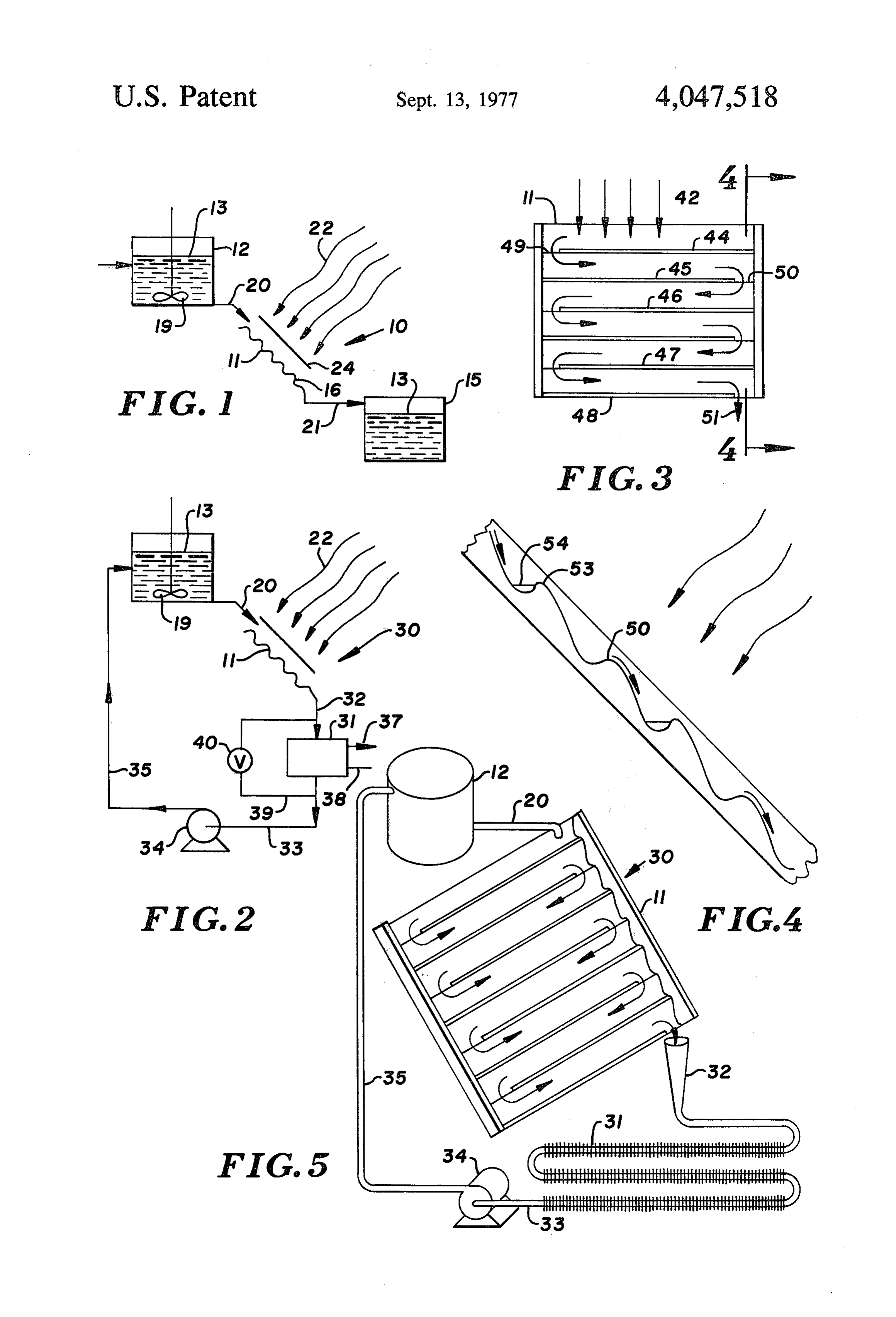
BRIEF DESCRIPTION OF THE DRAWINGS certain applications, it may be desirable to utilize an FIG. 1 is a schematic diagram of one typical embodi isolated chamber for the cell 11, and in such a situation, ment of the present invention; an infra-red transparent shield is provided such as is FIG. 2 is a schematic diagram illustrating a form or illustrated at 24. Obviously, edge surfaces will be pro embodiment of the present invention utilizing a circulat vided as well, but these isolating surfaces are not shown ing pump; here for purposes of clarity. FIG, 3 is a detail plan view of a solar energy gather Attention is now directed to FIG. 2 of the drawings ing cell prepared in accordance with the present inven wherein a modified form of embodiment is illustrated, tion; 10 and with this arrangement and system being shown FIG. 4 is a vertical sectional view taken along the line generally at 30. Where identical components are uti and in the direction of the arrows 4-4 of FIG. 3; and lized, identical reference characters will be utilized. In FIG. 5 is an isometric view illustrating one typical this arrangement, therefore, the energy extracting Zone embodiment of the present invention employing a recir is shown at 31 which is arranged to receive heated fluid culation system. 15 energy transfer medium from the cell 11 through con DESCRIPTION OF THE PREFERRED duit shown illustrated schematically at 32. Conduit 33 is EMBODIMENT utilized to transfer the medium from chamber 31 to circulating pump 34, and thence through conduit 35 to
Attention is now directed to FIG. 1 of the drawings return to chamber 12. In this arrangement, therefore, it wherein a schematic diagram is shown illustrating one 20 is possible to continuously maintain flow material aspect of the manner in which the invention may be through the system, with energy being extracted as practiced. In this illustration, the solar energy gathering required through heat exchanger or other device 31. In system generally designated 10 includes a cell 11 for the the event there is no call for additional energy in the transmission of a fluid energy transfer medium there system fed by conduits 37 and 38, bypass 39 along with through, with an input reservoir being shown at 12 for 25 appropriate valving as at 40 may be utilized. receiving and retaining a charge of fluid energy transfer Attention is now directed to FIG. 3 of the drawings medium therein, such as at 13, and with a receiving wherein the details of the flat plate collector solar cell receptacle or reservoir being shown at 15. The fluid 11 are illustrated. In this illustration, the carbon black energy transfer medium is arranged to pass through the ladened water is directed onto the surface of the struc cell, such as is illustrated by the appropriate arrows, and 30 ture 11 as at 42, with the structure having an array of the surface portion 16 of the cell is provided with a baffles, such as baffles 44-48 inclusive, with these baf black heat absorbant surface coating so as to enhance fles the amount of energy received and retained by this as atproviding 49 and 50, gates at alternate ends of the device such so as to provide a serpentine path for the surface. The fluid energy transfer medium 13 is nor 35 carbon black ladened mally translucent, and is also normally in the liquid state through end or terminalwater gate for ultimate discharge at ordinary ambient environmental conditions. The With attention being directed to FIG. 4 of the draw ordinary ambient environmental conditions are those ings, it will be observed that the device may, in certain conditions normally found for apparatus of this type, instances, employ a plurality of louvres for transferring and when water is employed as the medium, an anti the fluid energy transfer medium thereover, and expos freeze component may be added in the event any por ing a greater quantity tion of the system is subjected to temperatures below tion. In this system, ofalternate the material to incident radia barrier elements are 32 F. The fluid energy transfer medium is provided shown as at 53-53, with intermediate reservoirs being with a solar energy absorbing medium in order to en illustrated at 54-54, for receiving and retaining quanti hance the efficiency of the device. The solar energy absorbing medium is present in the fluid energy transfer 45 ties of fluid energy transfer medium as it cascades down medium in a quantity sufficient so as to render the me the the surface. It is this type of exposure which enhances ability of the material to maintain the carbon black dium substantially opaque. This condition will permit a properly dispersed through the system whenever neces substantial portion, if not all, of the incident radiation to sary.
be absorbed in the medium, and thereby effectively and Attention is now directed to FIG. 5 of the drawings efficiently transferred to the bulk solution. As an exam 50 wherein a further system is illustrated, with this system ple, when water is employed as the transfer medium, carbon black is preferred as an absorbant, while a dis being FIG.
based essentially on the schematic illustration of 2. In this arrangement, the typical residential persant such as, for example, Agar, gum arabic, sodium dwelling may be heated, or the heating plant supple alginate and it analogs, or a detergent such as octyl or mented by this system, with typical volumes, tempera nonylphenoxyethanol, as a dispersant. Pectins, gelatin, 55 polyvinylpyrrollidine, or colloidal clays may be utilized. tures and the like being scaled from the data provided in In order to assist the dispersant in maintaining the Table I hereinbelow.
carbon black in totally miscible condition, a stirring rod TABLE I or other arrangement is provided in the storage vessel 12, such as is illustrated at 19. This enhances the ability 60 A solar cell, open to the atmosphere, was designed of the system to maintain the energy absorbing material having inside dimensions of 38 x 11 inch. The base in proper suspension. Means are provided for passing was in the form of louvres, painted with "Rustoleum' the fluid energy transfer medium through the system, wrought-iron flat black paint, with the individual lou such as the conduit shown at 20, which delivers the vres extending with their axes parallel to the long direc transfer medium to the solar cell 11, and with conduit 65 tion of the cell. The louvres extended 10 inches, leav means 21 being illustrated schematically for delivering ing an opening at the ends so as to enhance fluid flow the heated medium from the cell 11 into the reservoir therethrough. The louvres were 1 inch, peak-to-peak, 15. Incident solar energy is shown as at 22, wherein this with the valley depth being inch.
Page 5scan →
In order to approximate window protection, the unit this fashion, therefore, the radiant energy passes was placed in viewing relationship to the sun through a through the material on two occasions, thereby reduc conventional "Thermopane'. glass, with these "Ther ing the quantities of loading material otherwise re mopane' structures being, of course, commercially quired. For example, and with particular attention being available. directed to Table I hereinabove, the carbon black was The cell was supplied with a medium having the effectively halved, while the base was polished to a following formulation: bright metallic reflective surface. The base, in this in stance, was in the form of a polished aluminum surface
Water 1 quart with a thin transparent metal-protecting film applied Carbon black 2 tablespoons O thereover so as to prevent oxidation of the aluminum ("Airflow" Carbon, Royal Charcoal per quart and consequent reduction in reflectivity. With this ex Co., Grain size 400-800 mesh)
Detergent
(Ajax household detergent) ml, ception in the carbon black content, as well as in the treatment of the metal surface, the remaining features were the same. In a test of the system, a heat gain of
The flow rate was 4 quarts per hour through the cell, from 21 C. up to 38 C. was achieved in 10 minutes. and the cell provided a heat gain in the material passing For the materials of construction forming the solar therethrough of 17. C. in the first 20 minutes, and exposed flat plate element, solar transmissive material continued to show heat gain for a period of 2 hours, at such as ordinary window glass may be utilized, along which time a temperature of 56' C. was achieved in the 20 with such alternatives as hard-tempered glass, Tedlar, medium. which is polyvinylfluoride film available commercially It will be appreciated that the solar energy gathering from the E. I. DuPont deNemours Corp. of Wilming system of the present invention may be applied to a ton, Del, or fiberglass filled epoxy. Each of these mate variety of systems, including, for example, heating of rials are known to transmit solar energy of a wave residence dwellings, heating of commercial establish length above 2800 - 3000 A. These elements work ments, gathering of energy for industrial operations, as 25 exceptionally well in a stationary unit such as a flat plate well as other uses. collector for rooftop or wall mounting. While carbon black is a preferred solar energy ab The structure of the present invention provides an sorbing medium for use in combination with water, oil, effective "liquid backed' flat plate collector in which or other commonly available liquids, it will be appreci in-situ absorbants are capable of providing a substantial ated that other absorbants may be used as well. As 30 quantity of effective solar energy absorbing surfaces. examples, it has been found that materials such as car I claim:
bon black in its various forms, including lampblack, 1. Solar energy gathering system including, in combi black platinum, copper sulfide, nickel sulfide, copper nation:
iron sulfide, asphalt for use with oil solvents, or the like.
The light absorbing materials are exposed, while travel 35 a. enclosed cell means including a generally solar transmissive fluid retaining zone with length and width ing through the solar cell, as suspended particles to dimensions substantially greater than the thickness incident solar radiation. These materials are then heated by exposure to this radiation and dissipate their thermal dimension, and with an inclined flat plate disposed energy through the carrying medium or otherwise. In for solar viewing and forming one wall of said en one embodiment, the light absorbing medium may be closure and having an inlet and an outlet for the maintained in dry state, exposed to solar radiation and transfer of fluid energy transfer medium there while in fluidized state, treated so as to dissipate ab through, surface means including said flat solar sorbed thermal energy. The suspending gas is prefer transmissive plate comprising the solar viewing ably effectively inert, such as CO, Argon, Helium, or wall of said cell means, an opaque solar radiation the like, in order to supress potential combustion. In 45 responsive plate forming a backing plate for said order to assist in following the sun, means may be pro cell means, and with said solar viewing wall and vided so as to maintain the cell 11 in a disposition which said backing plate being arranged to support, retain is substantially normal to the radiation from the sun. and expose said fluid energy transfer medium con Generally speaking, particle size should be in the range tained therein to incident solar energy; of from 100 mesh downwardly to colloidal sizes, with 50 b. a fluid energy transfer medium arranged to flow the smaller particle sizes generally being preferred. through said cell and comprising a fluid normally in It has also been found that the transfer of energy to liquid state at ordinary ambient environmental con the fluid energy transfer medium amy be enhanced if ditions and being normally translucent; the louvres along the surface of the cell are provided c, a solar energy absorbing medium in substantially with Mammut beads, these beads being provided so as 55 uniformly dispersed admixture with said fluid en to baffle the flow, and enhance the ability of the cell to ergy transfer medium and present in sufficient quan expose the fluid to incident radiation. tities so as to render said energy transfer medium as In most applications, a quantity of carbon black in a retained within said cell and between said solar range of approximately 2 tablespoons per quart of water viewing wall and said backing plate substantially has been found sufficient. Also, the quantity of disper opaque to incoming incident solar energy; sant employed is ideally in the range of 1 ml per quart, d. a dispersant in said fluid energy transfer medium with the dispersant being either octyl or nonylphenox for maintaining said solar energy absorbing medium yethanol. in substantially uniform dispersion within said fluid In a modified embodiment of the present invention, energy transfer medium;
and with particular attention being directed to FIG. 1 of 65 e. pumping means for forcibly transferring said fluid the drawings, the surface 16 is rendered reflective, that energy transfer medium through said system; is by polishing or the like so as to effectively reflect f. a heat extraction vessel for receiving fluid energy incident radiation back through the flowing fluid. In transfer medium from said cell means in liquid state 6 an inclined backing plate arranged to view incident and having at least one heat exchange surface for solar extracting thermal energy from said fluid energy energy and is reflective thereto. transfer medium; and 5. The solar energy gathering system as defined in g. said pumping means including means for recirculat claim 1 being particularly characterized in that said ing spent fluid energy transfer medium from said surface -means disposed within said cell means is ar ranged to view incident solar energy, and is coated with heat extraction vessel to the inlet of said cell means. a heat absorbing film.
2. The solar energy gathering system as defined in 6. The solar energy gathering system as defined in Claim 1 being particularly characterized in that said claim 5 being particularly characterized in that said fluid energy transfer medium is water and said solar 10 fluid energy transfer medium is water and said solar energy absorbing medium is selected from the group energy absorbing medium is selected from the group consisting of lampblack, black platinum, copper sulfide, consisting of lampblack, black platinum, copper sulfide, nickel sulfide, and copper iron sulfide. nickel sulfide, and copper iron sulfide. 3. The solar energy gathering system as defined in 15 claim7. The solar energy gathering system as defined in claim 1 being particularly characterized in that said sant means 6 being particularly characterized in that disper are provided in admixture with said fluid solar cell means, heat extraction vessel, and means for energy transfer medium in an amount of 0.1% disper transferring said fluid energy transfer medium are dis sant.
posed in a system isolated from direct exposure to ambi 8. The solar energy gathering system as defined in ent. 20 claim 2 being particularly characterized in that said 4. The solar energy gathering system as defined in solar energy absorbing medium is lampblack having a claim 1 being particularly characterized in that said particle size of below 100 mesh.
surface means disposed within said cell means includes
Provenance
- Collection
- Patents citing this work
- Pages
- 6
- Method
- pdftotext (the PDF's own text layer) + pdftoppm 300dpi page scans
- Patent office record
- patents.google.com →
- Source
- Google Patents citing-documents table
- Assignee
- John Harland Anderson
- Published
- 1977-09-13
- Transcribed from
- patentimages.storage.googleapis.com →