

patent · US4194949A
Solar distillation apparatus
25 March 1980
Text
Page 1bibliographic recordscan →
United States Patent (19)
Stark
54). SOLAR DISTILLATION APPARATUS
76 Inventor: Virgil Stark, 936 Fifth Ave., New
Related U.S. Application Data (63) Continuation-in-part of Ser. No. 810,761, Jun. 30, 1977,
807,513, each is a continuation-in-part of Ser. No.
(51) Int. Cl. ............................ B01D3/00; F24J 3/02 52 U.S. Cl. .................................... 202/180; 202/234;
58 Field of Search .................. 126/270, 271; 60/641;
1,683,266 9/1928 Shipman ............................... 26/271 1,704,173 3/1929 Chesney ... ... 126/271 1,951,403 3/1934 Goddard .. ... 126/27 2,920,710 1/1960. Howard ... ... 126/270 3, 159,554 2/1964 Mount ...... ... 1597 S 3,250,269 5/1966 Sherock ............................... 126/271 3,351,538 11/1967 Andrassy ..... 2O3/DIG. 1 3,428,529 2/1969 Gumucio.......................... 159/ S X 3,671,404 6/1972 Meckler .................... 203/DIG. 1 X 3,738,734 6/1973 Tait et al. ............................. 350/179 3,901,036 8/1975 Martin. ... 126/271 3,915, 148 10/1975 Fletcher ... ... 126/27 3,965,683 6/1976 Dix ....................................... 126/27 4,011,857 3/1977 Rice ..................................... 126/271 4,022, 186 5/1977 Northrup. ... 126/27 4,069,812 1/1978 O'Neill ................................. 350/21
FOREIGN PATENT DOCUMENTS
1 165672 10/1958 France ..................................... 26/270 Primary Examiner-Carroll B. Dority, Jr.
Assistant Examiner-Larry Jones
Attorney, Agent, or Firm-Kenyon & Kenyon
According to one aspect of the invention, a system is disclosed for substantially continuous distillation of water which comprises a plurality of parallel distillation units each comprising series of fluid and preferably also Fresnel-type lenses. Water to be distilled is preheated by circulating it through the fluid lenses on which evap orated water vapor is condensed to produce distilled water. The quantity of water circulated in the lenses is many more times the quantity of water evaporated by the solar energy concentrated by the lenses and con densed per unit of time to allow the circulated water to carry off heat recuperated within the lenses and the system. The preheated water circulated through the lenses is discharged into a central container in which the foci of the fluid and Fresnel-type lenses are located.
Secondary containers are provided to receive overflow from the central container since preheated water may be discharged into the central container faster than it is being evaporated. Preferably heat exchangers having a heat exchange fluid therein are provided in the second ary containers to recover heat from the water therein.
This system also may include or be combined with turbines and or a separate solar energy concentrator and collector used to superheat the heat exchange fluid and also preferably to heat excess water vapor removed from the distillation system and convert it to super heated steam and/or to externally condense the excess water vapor.
18 Claims, 28 Drawing Figures
Drawings

Page 2drawing sheetscan →
Page 3drawing sheetscan →
Page 4drawing sheetscan →
Page 5drawing sheetscan →
Page 6drawing sheetscan →
Page 7drawing sheetscan →
Page 8drawing sheetscan →
Page 9drawing sheetscan →
Page 10drawing sheetscan →
Page 11drawing sheetscan →
Page 12drawing sheetscan →
Page 13drawing sheetscan →
Page 14drawing sheetscan →
Page 15drawing sheetscan →
Page 16scan →
used but are uneconomical and impractical because of
SOLAR DISTILLATION APPARATUS the high cost involved. A conventional system for ob taining lower temperatures up to about 80 C. consists
CROSS-REFERENCE TO RELATED of dark-colored panels absorbing the solar radiation and APPLICATIONS means for removing the heat from the panels such as a This application is a continuation-in-part of Applica fluid system circulating a heat-carrying fluid in a heat tion Ser. Nos. 810,761 filed June 30, 1977, 807,513 filed exchanging manner with the panels. It is also known to June 20, 1977 and 806,291 filed June 15, 1977, Applica improve the efficiency of these systems by placing one tion Ser. Nos. 810,761 and 807,513 being continuation O or more glass plates above the panels to produce a s-in-part of Application Ser. No. 806,291, and Applica greenhouse effect for reducing heat losses. However, tion Ser. No. 810,761 being a continuation-in-part of the efficiency of these panel systems is low, from about Application Ser. No. 807,513. 30% to about 40%, and they require large spaces result BACKGROUND OF THE INVENTION ing in large heat losses, and they also require a high capital investment. The use of Fresnel-type lenses and 1. Field of the Invention fluid lenses is known in the art for focusing solar energy. The present invention relates to methods and appara See, for example, U.S. Pat. Nos. 3,915, 148; 3,125,091; tus for concentrating and collecting solar energy for 937,013; 3,965,683; 3,901,036; 60,109; 1,081,098; Japa many uses including the conversion thereof to heat nese Pat. No. 28-2130, and Australian Pat. No. 131,069. energy and/or electrical energy to be used for many 20 However, none of the known systems is capable of purposes. The present invention also relates to the stor converting and storing solar energy efficiently and none age and use of heat energy during hours without sun can produce heat at an economical capital investment shine or with reduced sunshine. The present invention such that the use of solar energy is competitive with further relates to methods and apparatus for the treat other forms of energy. The prior art also does not dis ment of liquids portably and in fixed locations including close obtaining temperatures in the order of a few hun water containing salt and/or other substances and to 25 dred degrees C. while also obtaining at the same time methods and apparatus for increasing the production of lower temperatures usable for home heating and water distilled water in distillation systems which include fluid lenses and preferably Fresnel-type lenses, heat exchang aheating system or other purposes. Nor is there in the prior art which is capable of storing heat energy from ers, turbines and condensers. Additionally, the inven solar energy tion relates to methods and apparatus using fluid and/or 30 any length ofduringtime periods of interrupted sunshine for and which also is capable of provid
Fresnel concentrating lenses and lens systems and elon ing different temperatures simultaneously and also uti gated collectors comprising at least on fluidcarrying lizing the luminous and utilizing or dispersing the heat conduit located at the foci of the lenses.
2. Description of the Prior Art produced by the infrared rays of the sun. The energy emitted by the sun corresponds to a high 35 With respect to electrical generation, it is known that temperature in the order of 6000 C., and is emitted in concentrating the solar energy at a photovoltaic cell the form of radiation which arrives at the earth with a will increase the electrical output of cell; however, wavelength distribution comprising about 3% ultravio there is the disadvantage that the increased heat in the let rays, 42% visible light rays, and about 55% infrared photovoltaic cell resulting from the concentration will rays. It is well known that surfaces exposed to the sun also limit the cell output. Known photovoltaic devices collect at least to some degree the solar radiation and produce a maximum of about one watt per hour per cell. that the absorption of this radiation results in a heating Assuming a cost of $10 per photovoltaic cell, a system of the material constituting the surface. It is also known using non-concentrated solar energy to generate about that electricity can be produced by photoelectric de 1 kilowatt per hour requires a capital cost of at least vices exposed to the sun's rays. 45 $10,000 which is not competitive for normal uses. There have been many attempts in the past to collect With respect to solar stills, known stills used for dis and utilize pollution-free and essentially nonconsumable tillation of seawater have low efficiencies and the cost solar energy to meet many energy needs. Much atten of heating the water is high as the least amount of heat tion has been directed to the conversion and utilization required to vaporize the water is not recovered from of Solar energy in the past few years because of the 50 condensation but rather is lost.
realization that fossil fuels are exhaustible and that a In accordance with the invention the prior art draw burning of these fuels produces pollution. Solar energy backs and disadvantages are substantially overcome and is inexhaustible and available above the clouds at an additional advantages realized.
average energy level of approximately 1350 watts per SUMMARY OF THE INVENTION horizontal square meter. A percentage of this energy, 55 depending on atmospheric and weather conditions, The present invention relates to methods and appara dust, pollution, etc., is available at the surface of the tus for concentrating, collecting, storing and utilizing earth during periods of sunshine which vary up to about solar energy and for lowering the cost and increasing 4000 hours per year depending on location. Even more the efficiency of solar energy systems. Refringent lens recently, the shortage of fossil fuels particularly oil and 60 means concentrate the solar energy along a length at natural gas and the high cost thereof have sparked new elongated collector means containing at least one fluid attempts to harness the energy of the sun. Heretofore, therein. The lens means comprise economical fluid and however, fuels were a less expensive source of energy /or Fresnel-type lenses (sometimes referred to as Fres than solar energy and the same problems of high capital nel lenses) and lens systems which focus the solar en cost and the cyclic nature of the sun requiring storage 65 ergy substantially along continuous lines or in lines of capability have heretofore not been satisfactorily substantially discrete points. Means are preferably pro solved. For example, refringent lens focusing systems, vided to maintain the focus lines or discrete foci within most using reflecting collectors, have heretofore been conduit means comprising the elongated collector 17 means regardless of the seasonal and preferably also the temperature fluid by, for example, circulating the lower hourly (daily) location of the sun and/or means are boiling point fluid past the higher boiling point fluid. provided for seasonally and preferably also hourly The invention also provides for the union of individ (daily) tracking the sun. Thus, the at least one fluid in ual systems and subsystems to form larger and compos the elongated collector means may be efficiently heated ite systems. Thus, a high degree of concentration of to high temperatures in order of a few hundred degrees solar energy and high efficiency are possible. Means C. may be provided to completely enclose the apparatus The fluid lenses comprise upper and lower solar en while permitting movement of the lens means and col ergy transmitting plates which are advantageously sepa lector means to track the sun seasonally or also hourly. rate plates installed in frame means in a fluid-tight man O Still further in accordance with the invention, both ner, or the fluid lenses including the plates may be the infrared and luminous rays of the sun may be simul formed by gluing, welding, extruding, or being blown taneously or individually utilized. Photoelectric cells, in a manner similar to that for glass or plastic bottles. specifically, photovoltaic cells, are disposed at the col The enclosure in the lens containing the fluid may ad lector means such that the luminous rays are concen vantageously be communicated with the collector 15 trated thereat for maximum electrical energy produc means to enhance performance. The fluid within the tion while the heat generated by the concentration of lenses preferably has a high index of refraction. The lens the infrared rays is removed by one or more fluids in the fluid and the distance between the lens plates may be collector means whose flow rates and volumes may be chosen to absorb varying amounts of infrared solar regulated. According to the invention, heating at the energy passing through the fluid. For example, more 20 photovoltaic cells is reduced by utilizing a fluid lens in infrared solar energy will be absorbed using, for exam which the lens fluid and lens plates absorb heat-produc ple, water as the lens fluid and less will be absorbed ing infrared rays which otherwise would be converted using a suitable transparent and colorless chemical to heat at the lens focus at the cells while permitting product having a high index of refraction. The heat electricity-producing luminous rays to pass to the cells absorbed by the lens fluid may be recovered and used to 25 with little absorption by the lens fluid and plates. preheat or heat fluid in the collector means or for other Concentration of solar energy may be increased by purposes. An antifreeze product may be added to the using several concentrators arranged to have a common lens fluid to prevent freezing of the lens fluid when it is focus. In one embodiment described for producting used in certain locations. It may be advantageous to electricity, this is achieved by employing a central fluid absorb infrared radiation in the lens fluid where it is not 30 or Fresnel (Fresnel-type) lens concentrating the solar desired to produce heat from the solar energy at the lens energy in a focus located at the photovoltaic cells and a focus such as in certain instances when focusing the plurality of Fresnel-type lenses located adjacent the solar rays on photovoltaic cells to produce electricity. central lens each provided with engravings thereon The elongated collector means preferably comprises angled to direct solar energy to the focus of the central a plurality of fluids, adjacent ones of which are contigu 35 lens. Heating of the photovoltaic cells is reduced by ous. The fluids are preferably isolated and disposed in utilizing a central fluid lens to absorb infrared energy adjacent conduits and the fluids preferably differ and and by placing the photovoltaic cells in collector means have varying boiling points. The theoretical focus or to remove heat therefrom produced by the infrared foci of the lens means are preferably on the surface of or energy thereat. This arrangement permits high concen within the higher or highest boiling point liquid. In a tration of solar energy with high conversion efficiency disclosed embodiment, the elongated collector means to electricity since heating of the cells is reduced. Thus, comprises at least two conduits; one of the conduits in accordance with the invention, the solar energy is containing a first fluid having a first boiling point is concentrated by a factor in the order of up to 100 so that located within a second conduit containing a second one of the known photovoltaic cells is able to produce fluid having a second boiling point. Preferably, the solar 45 up to 100 watts per hour instead of, for example, 1 watt energy is concentrated at the inner liquid which has a per hour during periods of sunshine. boiling point which exceeds that of the outer liquid. The The seasonal elevation position of the sun varies over conduits and fluids are solar energy transmitting or a total angle of about 47 during the year, the deviation opaque or darkened depending on the location of the between the equinoxes and each solstice being about lens means focus. By solar energy transmitting it is 50 23.5°. This deviation is important and in order to in meant that the solar rays are substantially transmitted crease solar energy collection throughout the year, sun through the material. In this way, the fluids may be tracking equipment may be used. For example, in late heated to different temperatures and accordingly can be October at a Latitude of about 43° N, the daily solar utilized for different purposes, if desired. Regulation of radiation received on a stationary horizontal surface is the fluid flow rates and selection of conduit sizes and 55 about 300 Langleys while that received by a surface shapes assist in providing different temperatures which maintained normal to the sun is about 680 Langleys, or may be utilized for different purposes. Arrangement of more than twice as much. Therefore, it is preferred, as multiple conduits carrying multiple fluids can provide mentioned, that sun tracking means be used or that energy for many different uses including vapor and other means be provided to maximize solar energy re super-heated vapor for mechanical devices and expan ception throughout the year. Both such means accord sion means including turbines, motors and engines; ad ing to the invention are disclosed.
vantageously, the lower boiling point fluid has a low In a disclosed embodiment, in which several concen latent heat of vaporization and is useful for this purpose. trators are arranged to have a common focus, a system Additionally, heat is stored in the higher boiling point of lenses concentrates the solar energy along a substan fluid permitting its temperature to rise during periods of 65 tially common focal line located in or on the elongated sunshine to a temperature substantially higher than that collector means during the different seasons and prefer of the lower boiling point fluid which may be used as a ably during the different times of day without using sun working fluid. Heat is removed from the higher boiling tracking means. This system includes an elongated cen 18 tral Fresnel-type or fluid lens concentrating the solar the reflectors seasonally reflecting a substantial amount energy along a focal line, and elongated Fresnel-type of solar energy which is focused in or on the collector lenses located adjacent to and at an angle with respect means. However, to further increase collection, means to the central lens, the adjacent Fresnel-type lenses may be provided to rotate the entire system (the reflec being provided with engravings angled to direct the tors, lens and collector means) generally about an east solar energy to the focus of the central lens. The lenses west or longitudinal axis for seasonal tracking of the sun are oriented so that they are elongated generally in the and preferably also about a north-south or transverse east-west direction. A given lens or lenses primarily axis for daily tracking of the sun. A fluid lens(es) is concentrates the solar energy along the focal line for , provided when it is desired to reduce the concentration given times of the year. For example, the central lens of infra-red energy at the collector means or to produce primarily concentrates the solar energy during the time heat in the lens fluid of the fluid lens. As mentioned, the closely before and closely after the equinoxes while one lens fluid and the distance between the lens plates may adjacentlens primarily concentrates the solar energy up be chosen to absorb varying amounts of infrared en to one solstice and the other adjacent lens during the ergy. If desired, photovoltaic cells may be located in the time up to the other solstice. In the embodiment in 15 collector means. Systems according to this aspect of the which the central lens is a Fresnel-type lens, the lens invention may increase solar energy collection by over system perferably includes sets of Fresnel-type lenses in 100 times.
the elongated or east-west direction. The Fresnel-type The present invention further relates to distillation of lenses located towards the extreme east and west ends liquids in which water or other liquids may be distilled of the lens system are positioned at an angle with re 20 by locating the lens means focus in the water or liquid to spect to the inner lenses so that a given lens or lenses be distilled, above which is positioned the lens means primarily concentrates the solar energy along the focus and a downwardly sloping substantially smooth, prefer at given times of the day. However, such lenses may ably planar surface, whereby the liquid is evaporated also be located intermediate the east and west ends in a and condenses on the smooth surface which carries the lens system comprised of many lenses oriented along 25 condensed liquid to a collecting vessel positioned below the east-west direction. Thus, at different times of the the lower side thereof. Preferably, the planar surface is day and year, one or more lenses will primarily concen inclined at a slight angle with the horizontal, for exam trate the solar energy along the focal line without using ple about 15, and is cooled to enhance condensation sun tracking equipment. It is preferred in these embodi thereon. It is preferred that the lens means for the water ments that the elongated collector means comprise two 30 distilling apparatus comprise a fluid lens which includes or more adjacent elongated fluid-carrying conduits and preferably cools said smooth surface. In some em each of which encloses another fluid-carrying conduit. bodiments, conduit means are located in the liquid to be According to one aspect of the invention, lower re distilled. It is preferred that the fluid forming part of the flectors are disposed below a central reflector and posi fluid lens is circulated within the conduit means where tioned to reflect and preferably concentrate solar en 35 one is employed to advantageously utilize the latent ergy towards the central reflector. The central reflector heat released by the vapor condensing on said smooth reflects and preferably concentrates the solar energy surface and transferred to the liquid to be distilled. It is from the reflectors towards the collector means, also preferred that the lens fluid be the same liquid as the one disposed below the central reflector. A lens, preferably being distilled, salt water for example, and be circulated a fluid lens, is disposed in the path of reflected solar in the vessel containing the liquid to be distilled to heat energy between the lower reflectors and the collector. or preheat the liquid in the vessel. In a disclosed em The lens(es) is positioned in the path between the lower bodiment, distillation apparatus includes both fluid and reflectors and the central reflector and/or in the path Fresnel lenses in which the fluid lens is fixed and the between the central reflector and the collector means, Fresnellens is, if desired, movable. The heat released by the reflected solar energy being focused in or on the 45 the condensing liquid on said smooth lens means surface collector means by the lens or central reflector. The is not lost and returned to the system in the conduit reflectors are preferably concentrating reflectors and means in the vessel containing liquid to be distilled, or are preferably cylindrical linear reflectors or paraboic elsewhere, and/or the heat absorbed and recuperated linear reflectors. The reflecting surfaces of the reflec by the lens fluid may be used to preheat or heat the tors may be of polished metal, for example, aluminum, 50 incoming liquid to be distilled in the distillation appara and the bodies of the reflectors may be made of epoxy tus or used for other purposes such as producing elec fiberglass. The reflecting surfaces and the bodies of the tricity by superheating suitable low boiling temperature reflectors may also be made of glass and other materials. fluids and expanding them in expansion means such as The collector means preferably comprise multiple con turbines and engines, thereby increasing substantially duits, one located in another, the central reflector or the 55 the efficiency of the system. Additionally, it is preferred lens focusing the reflected solar energy into a substan that the condensed liquid be circulated in the conduit tially continuous and linear focus preferably located in means in the vessel containing liquid to be distilled or the innermost conduit. In a preferred embodiment ac elsewhere to utilize heat contained in the condensed cording to this aspect of the invention, the lens(es) is a water. The solution of salt (NaCl) dissolved in water fluid lens(es) located between the central reflector and 60 absorbs less infrared rays than water alone. Thus, where the collector means and concentrates the solar energy it is desired to reduce absorption of infrared rays in the reflected from the central reflector into an elongated lens fluid, a salt/water solution is preferably used as the focus located in or on the collector means. According lens fluid. When desalinating sea water, the sea water is to this aspect of the invention, concentration of solar preferably used as the lens fluid and preferably is also energy may be increased without providing means to 65 introduced preheated into the container holding the track the sun's position, the reflectors and lens being water to be distilled.
disposed so that the solar energy is reflected and con In the case of sea water, salt may be produced from centrated throughout the year and with at least one of the resulting concentrated brine and credit obtained 19 from the sale thereof to lower the overall cost of obtain heated by the solar energy concentrated by the lenses, ing distilled water. Heat may also be recovered from the for example, to a temperature which may be about 85 heated brine discharged from time to time from the C. to rapidly evaporate the water, the vapor being con system. According to the invention, combination con densed on the flat bottom plates of the fluid lenses and centrator systems including both fluid and Fresnel the condensate flowing off the plates into an adjacent lenses can be advantageously used. In one such combi container. The heat recuperated from the released heat nation system, one set of fluid lens concentrators is of condensation of about 539 kcal/liter (975 BTU/lb) in inclined, for example, south at 15 with the horizontal, addition to the heat produced in the water in the fluid with the bottom plates of the lenses being cooled by lenses by absorption of infrared energy is carried by the fluid circulating within the lenses whereby the vapor 10 water circulated through the fluid lenses. This heat condenses on the cooled bottom plates and flows there increases the temperature of the water circulated in the along into an adjacent vessel. Another set of Fresnel lenses, from an influent temperature of, for example, concentrators or fluid lenses are provided to receive the about 20° C. to an effluent temperature which may be, sun's rays during hours of sunshine to primarily heat for example, about 70° C. with a predetermined, rela fluids having high boiling temperatures to over 200 C. 15 tively high quantity and rate of circulation, which may in conduit means in the vessel containing liquid to be be regulated. The quantity of water circulated through distilled. The heat in the high boiling temperature fluids the lenses in raising the effluent water temperature to is stored and used primarily during periods without about 70° C. is many more times (for example, as high as sunshine whereby evaporation and condensation of the or even higher than about 10 times) the quantity of vapor on the cooled bottom plates of the fluid lenses 20 water evaporated by the solar energy concentrated by continues during periods without sunshine. The Fresnel the lenses and distilled per unit of time since the water lenses or a separate set of fluid lenses used to heat the is progressively heated as it is circulated and is therefore high boiling temperature fluids to store heat are prefera circulated faster than it is evaporated. The overall quan bly provided with tracking means to follow the seasonal tity of water evaporated may be up to the quantity of and preferably also the hourly location of the sun. Ac 25 water circulated in the lenses due to heating of the cording to one embodiment of the invention, the distil water in the lenses and to heating of the water with heat lation apparatus comprises a plurality of sets of fluid recuperated elsewhere in the system. In accordance lenses. One set of lenses has a lens plate separation at the with the invention, means are provided to receive the point of maximum separation of, for example, one inch effluent heated or preheated water circulated through for minimum absorption of infrared rays and maximum 30 the lenses which is in excess of the water being evapo evaporation of the water to be distilled during periods rated. A plurality of fluid lenses is advantageously dis of sunshine. This set comprises smooth surface bottom posed in parallel, one series of lenses being tilted north lens plates for condensing the vapor thereon which are and another series of lenses being tilted south. The inclined to flow the condensate into a vessel located water is preferably circulated in opposite directions in below the edges thereof. The lens fluid in this set of 35 adjacent sets of lenses of a series to maintain the water lenses will cool the bottom lens plates to provoke con temperature in one set of the series of lenses cooler, densation thereon. Another set of lenses having a lens thereby assisting condensation of evaporated water on plate separation at the point of maximum separation for the bottom plates of that set. A plurality of Fresnel-type example of four inches is used for high absorption of lenses may advantageously be added between the series infrared rays and contains a high boiling point (for ex 40 of fluid lenses, one series being tilted north and another ample about 200 C.) lens fluid which is communicated series being tilted south to increase the concentration of with a plurality of conduits located in the water to be solar energy in the water to be distilled for increased distilled. This set of lenses and conduits is used primar production of distilled water. The Fresnel-type lenses ily for storing heat as described hereinbefore to be used facing south are preferably tilted at an angle of 10 more during periods without sunshine to continue the distilla 45 than the angle of latitude of the location of the system to tion. The lens fluids for both sets of lenses recuperate further increase collection of solar energy and reduce heat absorbed by the lens fluids as described hereinbe heat loses. In a preferred embodiment, water discharged fore. The use of the different fluid lenses increases pro from the lenses into the container containing the water duction of distilled water and increases the efficiency of to be distilled and not evaporated or released periodi the system. According to one embodiment, the lens or SO cally as concentrated, undistilled water overflows, for lens system focus is located in the water to be distilled example, into adjacent containers. The temperature of such that the location of the focus remains in the water the water overflowed into the adjacent containers may to be distilled with the changing location of the sun. be, for example, about 80° C. The heated water in the This eliminates the need for means to move the lens or adjacent containers acts to store the heat obtained by lens system to maintain the focus thereof in or on an 55 circulation of the water through the fluid lenses which elongated collector. In another embodiment of the in heat may also be used to produce more vapor and more vention, the still is portable and is easily assembled and condensate. The heated water in adjacent containers disassembled. Advantageously, the stills are operative may also be used to evaporate low boiling temperature to distill seawater and brackish water and the portable fluids having low latent heats of vaporization such as stills in particular may be used at sea, for example, on 60 Freon (-20.8° C. boiling temperature for Freon 12, life boats, and in desert areas. 23.8° C. boiling temperature for Freon 11), butane, In still another embodiment of the invention, the monochlorobenzine, etc. Freon 12 vapor at 70° C. (158 liquid to be distilled, which may be water, is flowed first F.) will have a pressure of about 300 psig (16 atm.) and through fluid lenses and heated or preheated, for exam when expanded in a turbine or engine can produce ple, up to about 70° C. (Water will be used in connec 65 electrical and/or mechanical power. The low boiling tion with the further description of this embodiment). temperature fluid is circulated in heat transfer means The heated water is then introduced into the container inside the adjacent containers, supplied to the turbine or containing the water to be distilled where it is further engine and recirculated after expansion in the turbine or 20 engine. The low boiling temperature fluid may be pre salt is significant. The salt-rich brine may also be elec heated by the water in the adjacent containers to a trolysized using in part electricity generated as de temperature which may be, for example, about 60° C. scribed above to produce sodium and chlorine. Since 5 Heat transfer means may also be installed in the contain kwh of electrical energy per kilogram of chlorine (chlo ers containing the warm condensate, which may be at a 5 rine comprises about 60% of the weight of the salt) are temperature of about 80 C., to further increase the required in the electrolysis of the brine, additional elec temperature and pressure of the low boiling tempera tricity is required and may be provided from additional ture fluid and the power obtainable therefrom. The systems which convert solar energy to electricity. In adjacent containers may also be used to store the heat in . the event that not all of the water vapor produced by the overflowing water, the stored heat assisting in pro- 10 the distillation system is condensed on the bottom plates viding substantially continuous operation and increas of the fluid lenses and a sizable quantity of water vapor ing production of distilled water. Systems according to is available which may be at, for example, 80° C. or this embodiment of the invention may be disposed in more, the invention further provides for removing parallel to provide a composite system comprised of a vapor from the distillation system, compressing the plurality of individual systems. In such a composite 15 vapor, heating it to produce steam and introducing the system, common containers may be provided for the steam into a turbine to generate power, the exhaust condensate of adjacent units to reduce heat loses and steam being condensed by cooling using the water to be capital expense. Heat may also be obtained directly distilled and the condensate obtained providing addi from solar energy in a separate system and used to heat tional distilled water. Additionally, excess vapor may the low boiling temperature fluid. The fluid heated, for 20 be removed from the distillation system and externally example, to about 60° C. by the recuperated heat, is circulated in a seperated collector of the separate solar condensed water is using water to be distilled. The condensed discharged into the adjacent container to add to energy system which is preferably provided with fluid the distilled water produced. Most of the heat of con lenses and/or Fresnel-type lenses as concentrators. The densation of the condensed exhaust steam and the con fluid can then be heated to higher temperatures by the 25 densed water vapor is recovered and transferred to the concentrated solar energy in high pressure conduits. water to be distilled. Preferably the collector of the For example, Freon 12 heated to 100° C. will have a pressure of about 480 psig or 32 atm. Other fluids may separateother, system includes two conduits, one inside the with the lens system being focused in the inner be heated to even higher temperature such as over 200
C. The superheated vapor of the fluid can thereafter be 30 conduit as described hereinbefore, a high boiling tem perature fluid such as glycerine being circulated in the expanded in the turbine or engine and produce electric inner conduit and water to be distilled being circulated ity. The combination of the distillation system and the in the outer conduit. Further in accordance with the separate solar energy system produces electricity at high efficiency since the fluid is preheated to about 60' example tothe invention, high boiling temperature fluid, heated for temperature which may be about 250 C.,
C. by heat obtained from the distillation system. Addi- 35 tionally, the separate solar energy system is preferably is used to superheat the compressed water vapor to a movable (lenses and collector) to track the seasonal and temperature which may be, for example, about 200 C. daily movement of the sun and is able to improve effi bine. The superheated steam is then introduced into the tur ciency by providing large radiation surfaces for the the high After superheating the compressed water vapor, concentrating lenses and the collector which may be 40 superheatboiling the temperature fluid may also be used to low boiling temperature fluid to a temper more than double those prevailing on the horizontal surface at the location of the system. Providing a sepa ature which may be, for example, about 200 C. after it rate solar energy system is particularly advantageous has been heated to about 60° C. in the adjacent contain since it can more easily be made movable to track the ers and before the fluid is introduced into the turbine as sun in comparison to a distillation system. When distill- 45 described above.
ing seawater, the electricity obtained may be used in the Lenses may also be combined according to the inven electrolysis of salt to produce sodium and chlorine from tion so that the solar rays pass through the lenses seri the brine remaining after distillation of the seawater. ally wherein the focal length of the lenses may be short Electricity may be produced in combination with the ened and/or a sharper focus of the lens system may be solar energy distillation of liquids, particularly water, 50 provided. Bi-convex fluid lenses having convex upper using fluids heated by solar energy and turbines as de and lower plates may also be provided to shorten the scribed above and/or electricity may be produced in lens focal distance to collector means. combination with distillation using photovolatic cells as Apparatus according to the invention may be used to described hereinbefore. As mentioned, the quantity of electrolyze water and salt recovered from distillation. water circulated through the fluid lenses may be ten 55 Hydrogen, sodium and chlorine may be recovered from times greater than the quantity of water that is evapo the electrolysis. The recovery of these products further rated per unit of time in order to contain the recuper increases the economic efficiency of the apparatus. Ad ated the heat of condensation of the water vapor con ditionally, the hydrogen may be used as a non-polluting densing on the bottom plates of the fluid lenses. In the fuel or used with carbon monoxide to produce metha case of seawater, the brine remaining as the water dis- 60 nol, or with nitrogen of the air to produce ammonia charged from the fluid lenses is evaporated or over fertilizer and other nitrogen products such as nitric acid flows will become concentrated with salt and will con and urea.
tain considerable heat. Part of this heat may also be Still further in accordance with the invention, appa recuperated and used, for example, to preheat the water ratus disclosed herein for producing electricity may be to be distilled when the brine is discharged from the 65 combined with hydroelectric means and apparatus dis system from time to time. The salt may be extracted closed herein may be combined with heat pumps and/or from the brine and considering that the salt may com refrigeration apparatus and/or expansion means such as prise 50% of the weight of the brine, the recovery of the turbines, motors and engines.
Page 21scan →
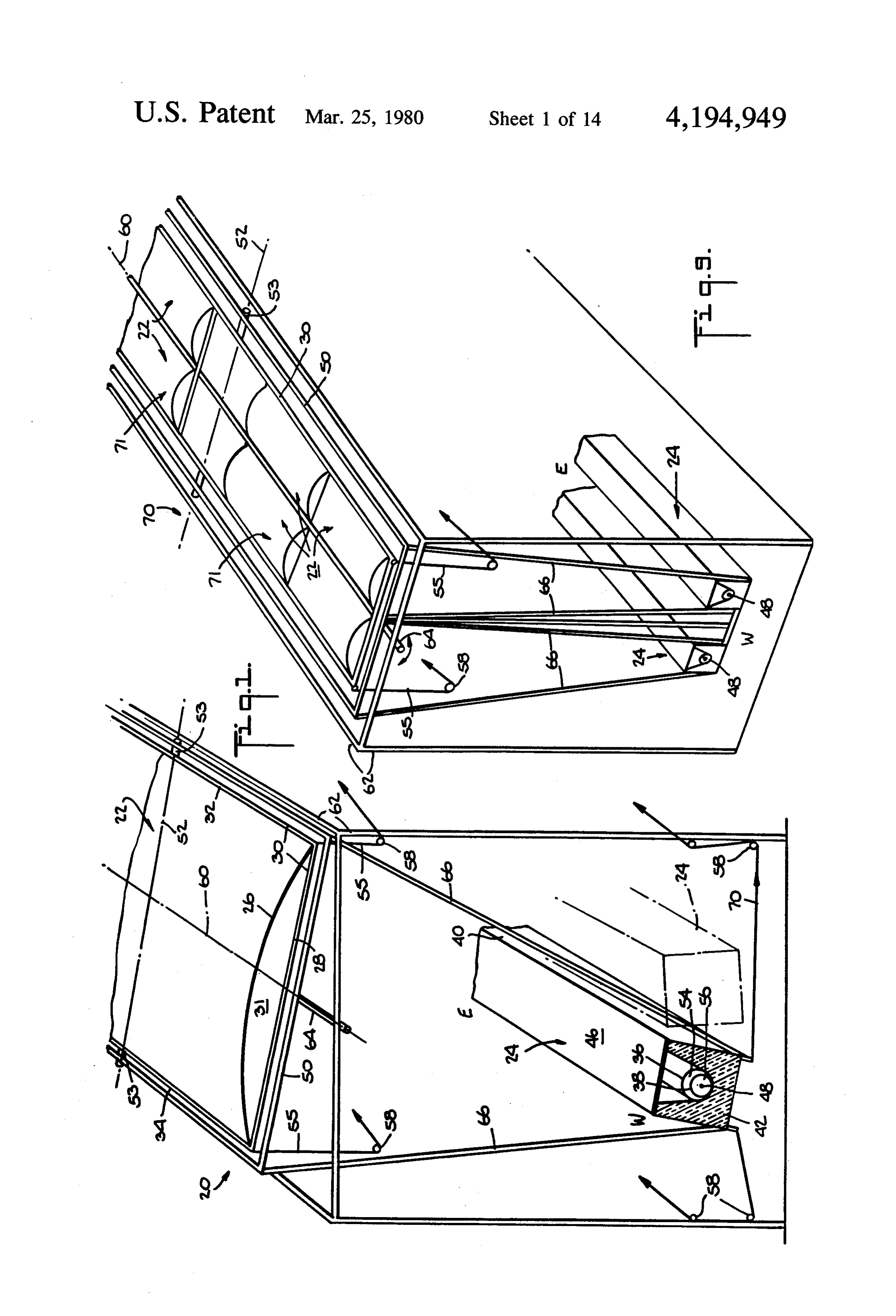
Still further in accordance with the invention, appa conduit, the individual systems being enclosed and the ratus and methods having high efficiency and low cost lenses and collectors being interconnected as described for concentrating, collecting and converting solar en for FIG. 1;
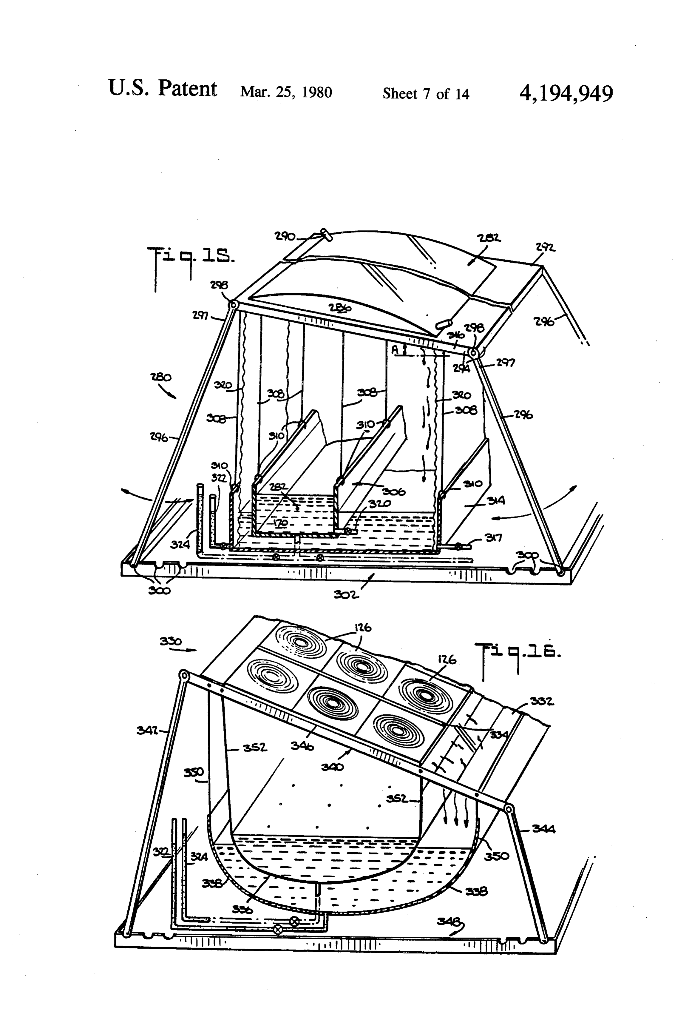
ergy are disclosed. FIG. 15 is a schematic perspective diagram of a por These and other aspects of the present invention will 5 table, easily assembled and disassembled system having be more apparent from the following description of the a fluid lens for distilling water;
preferred embodiments thereof when considered with FIG. 16 is a schematic perspective diagram of an the accompanying drawings. other portable easily assembled and disassembled sys tem having Fresnel lenses for distilling water;
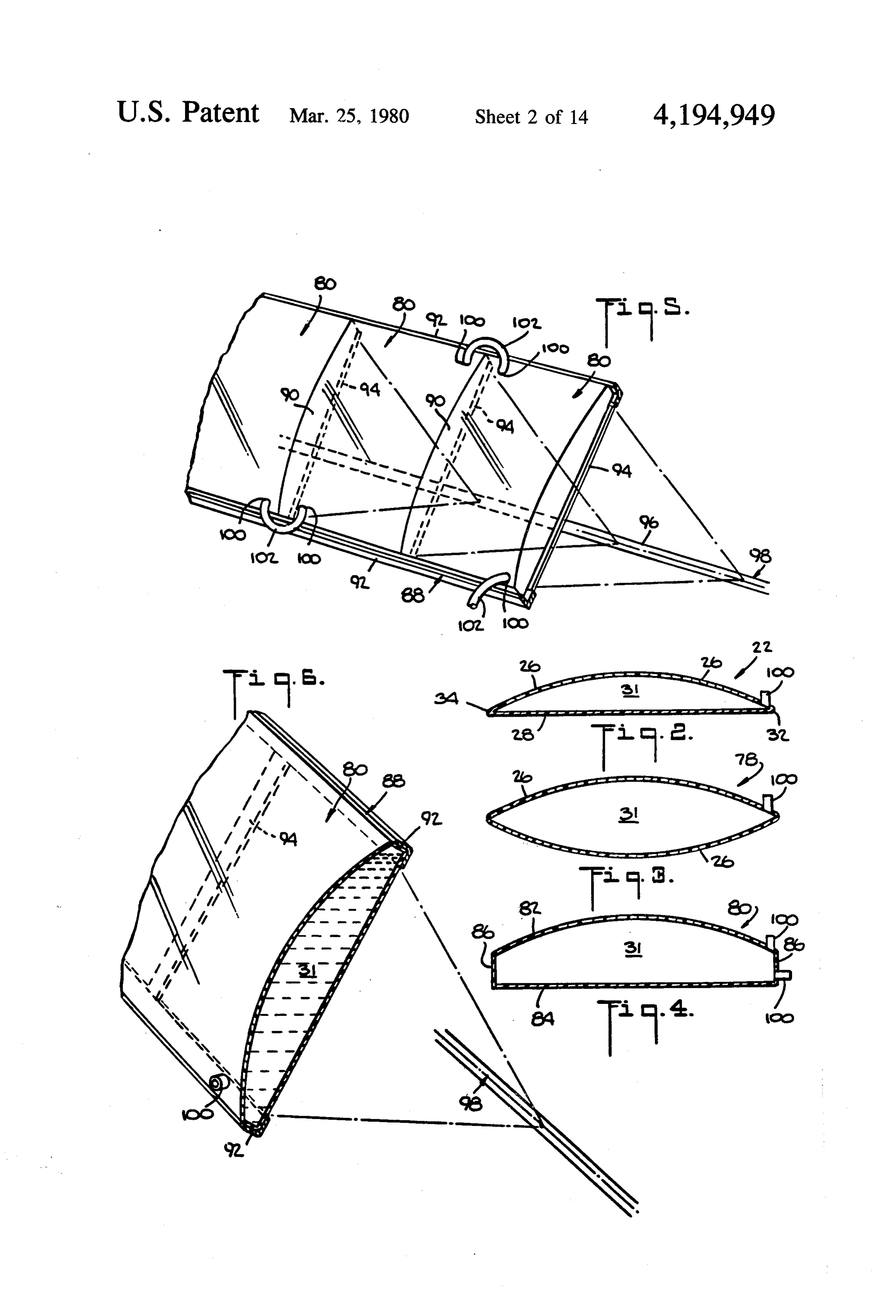
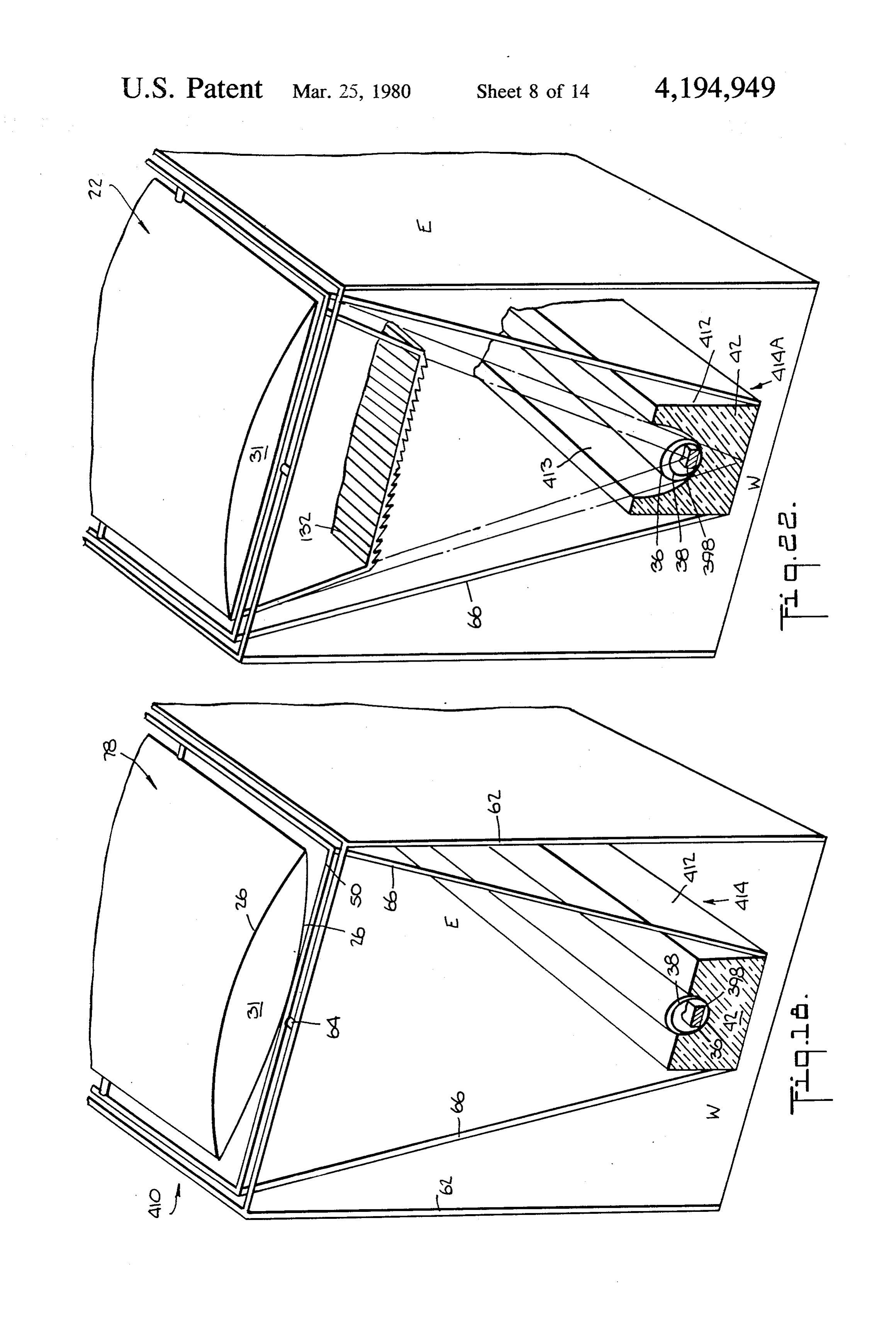
BRIEF DESCRIPTION OF THE DRAWINGS FIG. 17 is a cross-section view of a photovoltaic cell The present invention is illustrated by way of exam positioned in a fluid-carrying conduit to produce elec ple and not limitation in the figures of the accompany tricity from solar energy with fluid circulating inside ing drawings in which like numerals refer to like parts and/or outside the conduit to remove heat; and in which: FIG. 18 is a schematic perspective diagram showing FIG. 1 is a schematic perspective diagram showing a 15 a system comprising an elongated, bi-convex fluid lens system including an elongated fluid lens and an elon having a shortened focal length focused on a collector gated collector, the lens being movable about a trans having photovoltaic cells therein in which the top of the verse axis to track the sun's daytime location and the collector is exposed to disperse heat produced thereat lens and collector being interconnected and movable by the infrared rays, the fluid lens being movable and about a longitudinal axis to track the sun's seasonal 20 interconnected with the collector to track the seasonal location; and daily location of the sun as described in FIG. 1; FIGS. 2-4 are cross-section views showing different FIG. 19 is a schematic cross-section view of a lens configurations of fluid lenses; system including a central fluid lens and adjacent Fres FIG. 5 is a perspective view showing a series of lon nel lenses each having engravings thereon angled to gitudinally juxtaposed fluid lenses and means for inter- 25 provide the Fresnel lenses with the same focus as that of communicating the enclosures of the respective lenses, the fluid lens, the common focus being located at an this arrangement being utilizable to arrange a plurality elongated collector which is interconnected with the of longitudinally juxtaposed lenses where a single lens is lenses, both the lenses and collector being movable to shown; track the sun's position;
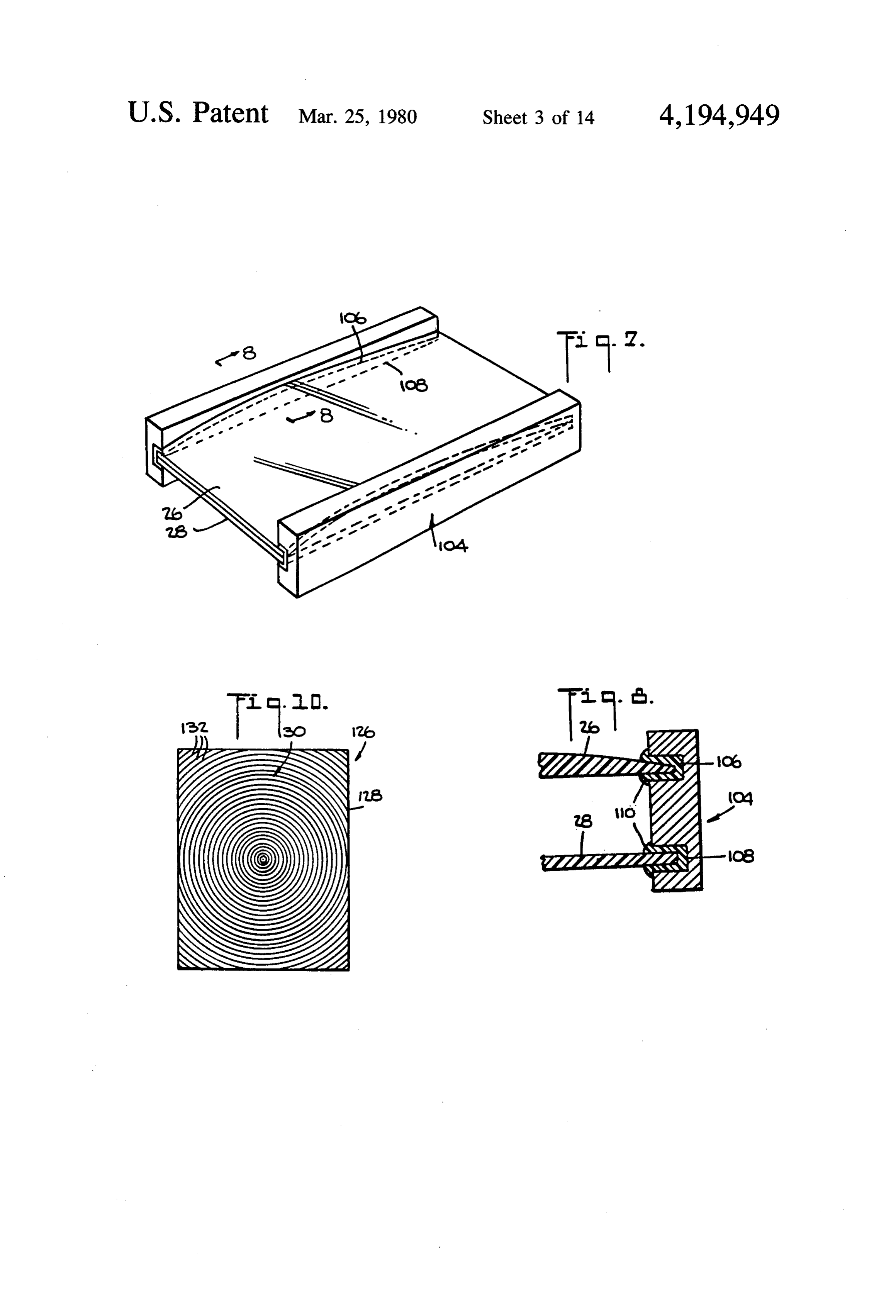
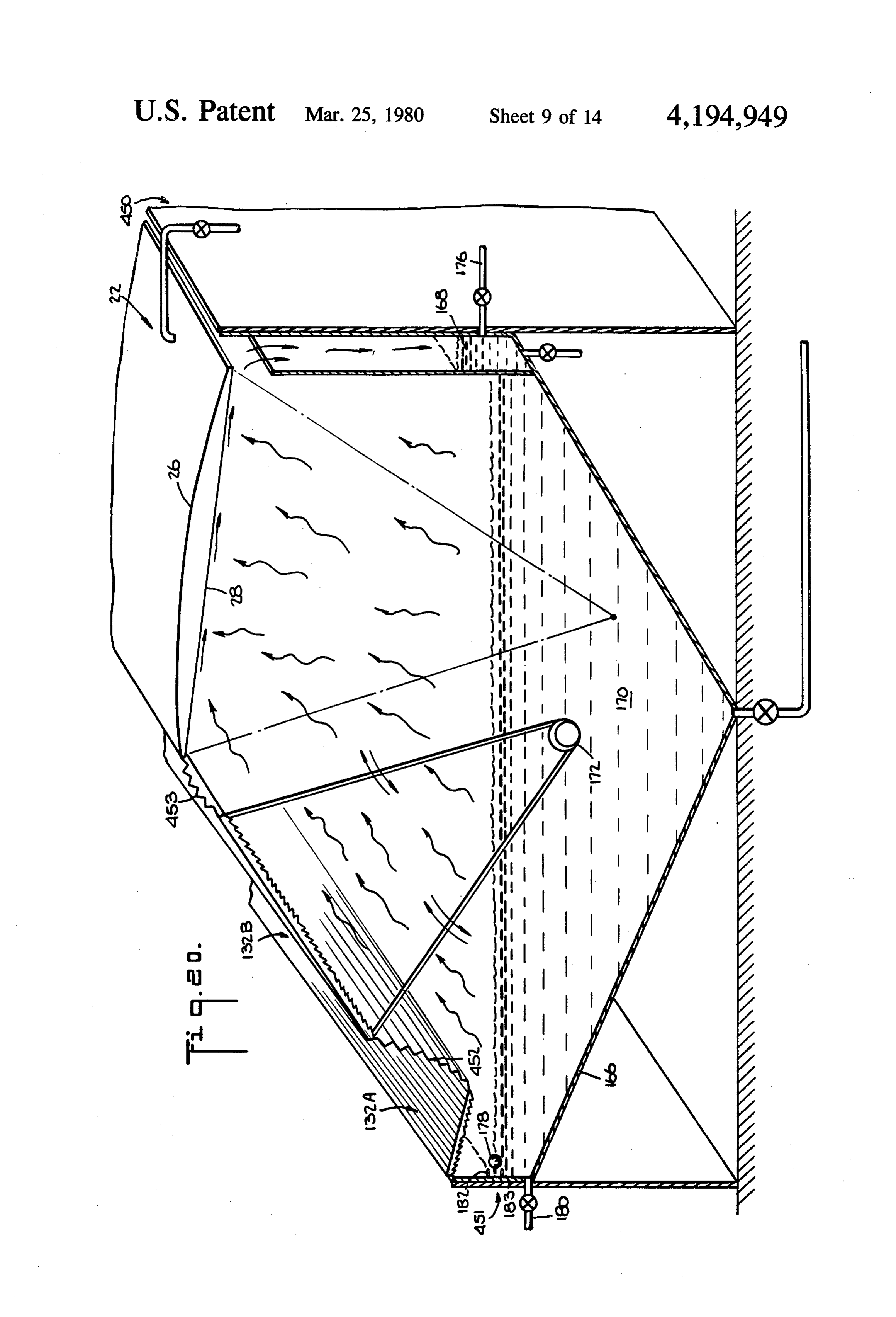
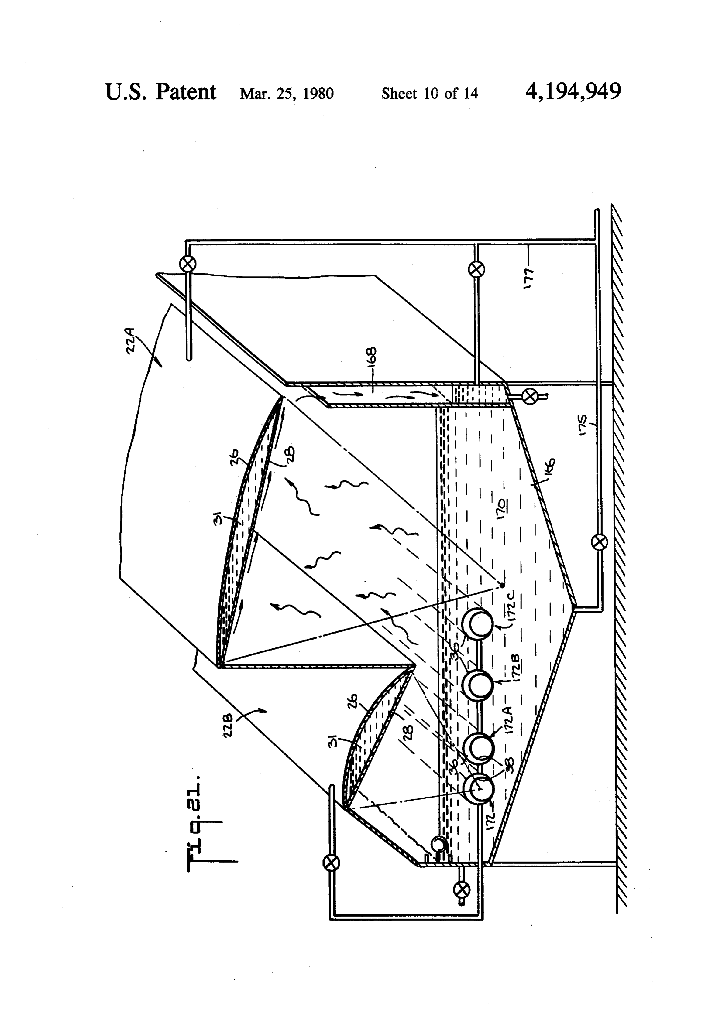
FIG. 6 is a detail perspective view of FIG. 5 showing 30 FIG. 20 is a schematic perspective diagram showing the lens frame; a system for substantially continuous distillation of FIG. 7 is a perspective view of a lens system compris water in which the lens system comprises Fresnel and ing two separate plates for enclosing a lens fluid and a fluid lenses and has a plurality of foci located at differ frame for sealing the plates into a fluid-tight lens; ent depths in the water to be distilled, a Fresnel lens and FIG. 8 is a cross-section view of the lens and frame of 35 collector being movable to track the seasonal location FIG. 7 taken along line 8-8; of the sun and a set of lenses for preheating the incom FIG. 9 is a schematic perspective diagram showing ing water to be distilled;
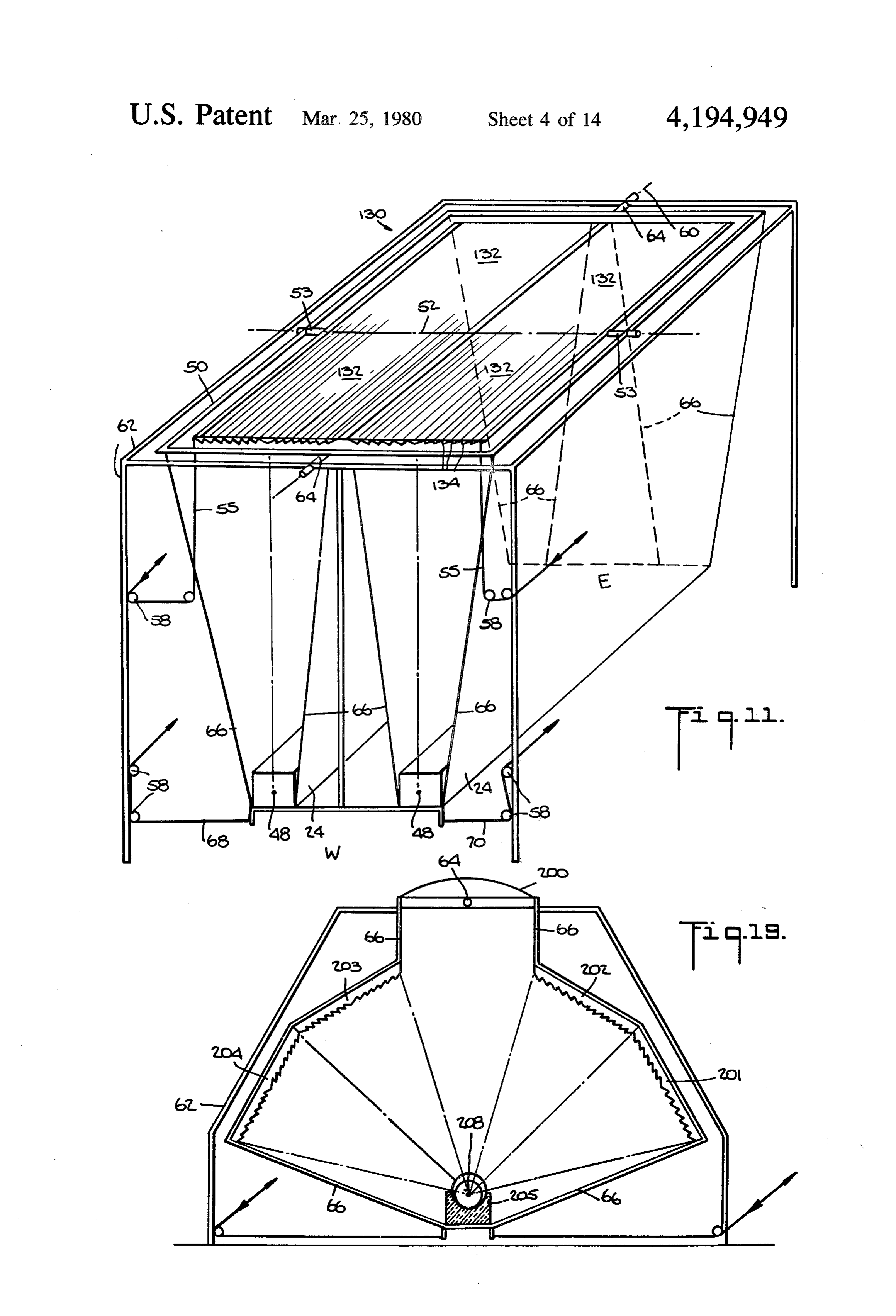
another system in which panels of four fluid lenses each FIG. 21 is a schematic perspective diagram showing are arranged longitudinally and are focused on elon another system for distilling water in which the lens gated collectors, the panels and collectors being inter- 40 system comprises two fluid lenses and a plurality of connected and movable on a shaft rotated to track the conduits to provide substantially continuous operation; sun's seasonal location and the lenses being movable FIG. 22 is a schematic perspective diagram showing about a common transverse axis to track the sun's day two lenses through which the solar rays pass serially to time location as described in FIG. 1; provide a sharper focus at a collector similar to the one FIG. 10 is a plan view of a planar, point-focusing, 45 of FIG. 18, the lenses and collector being movable to Fresnel-type lens; track the sun;
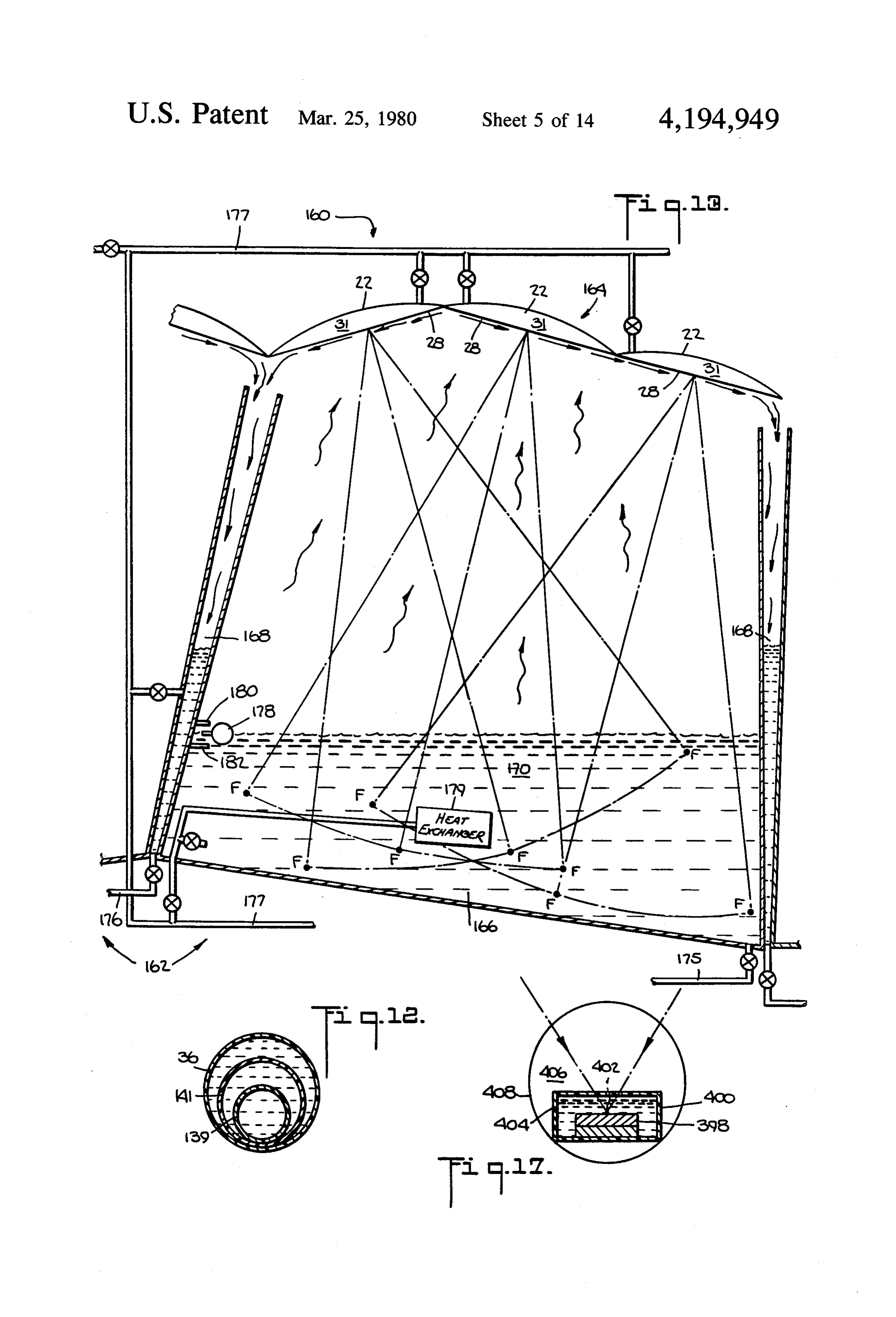
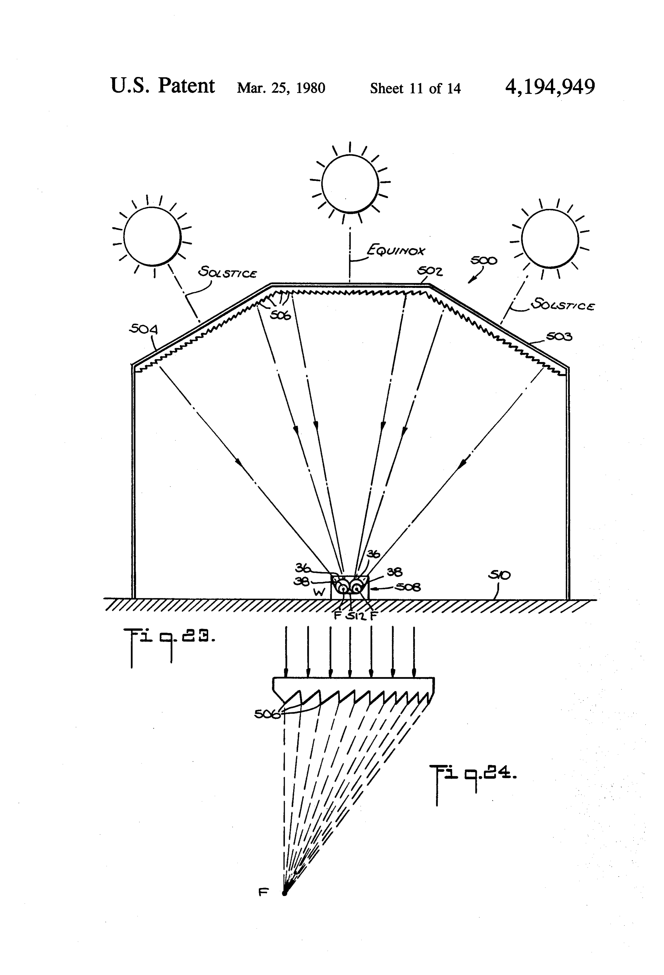
FIG. 11 is a schematic perspective diagram showing FIG. 23 is a schematic cross-section view showing a another system comprising elongated, planar Fresnel lens system including a central lens and adjacent Fres lenses having a linear focus and collectors comprising nel-type lenses each having engravings thereon angled fluid-carrying conduits, the lenses and collectors being 50 to provide the adjacent Fresnel-type lenses with the interconnected and movable as described for FIG. 1; same focus as that of the central lens, the lenses being FIG. 12 is a cross-section view of part of another positioned to place the lens system focus in or on a collector comprising three fluid-carrying conduits in collector having two adjacent elongated conduits each which the innermost conduit is enclosed by the interme enclosing another conduit during different times of the diate conduit which is enclosed by the outermost con- 55 year without using sun tracking means; duit; FIG. 24 is an enlarged schematic cross-section view FIG. 13 is a schematic perspective diagram of a com showing one of the Fresnel-type lenses of FIG. 23; posite system for distilling water comprising individual FIG. 25 is a schematic perspective diagram showing systems each including three elongated fluid lenses, two a set of Fresnel-type lenses oriented in the east-west lenses being located on the same plane and the third at 60 direction with the lenses at the east and west ends an an angle to the two, the foci of the lenses being located gled with respect to the inner lens, a given lens primar in a vessel containing the water to be distilled at differ ily concentrating the solar energy in or on the collector ent locations therein; at given times of the day;
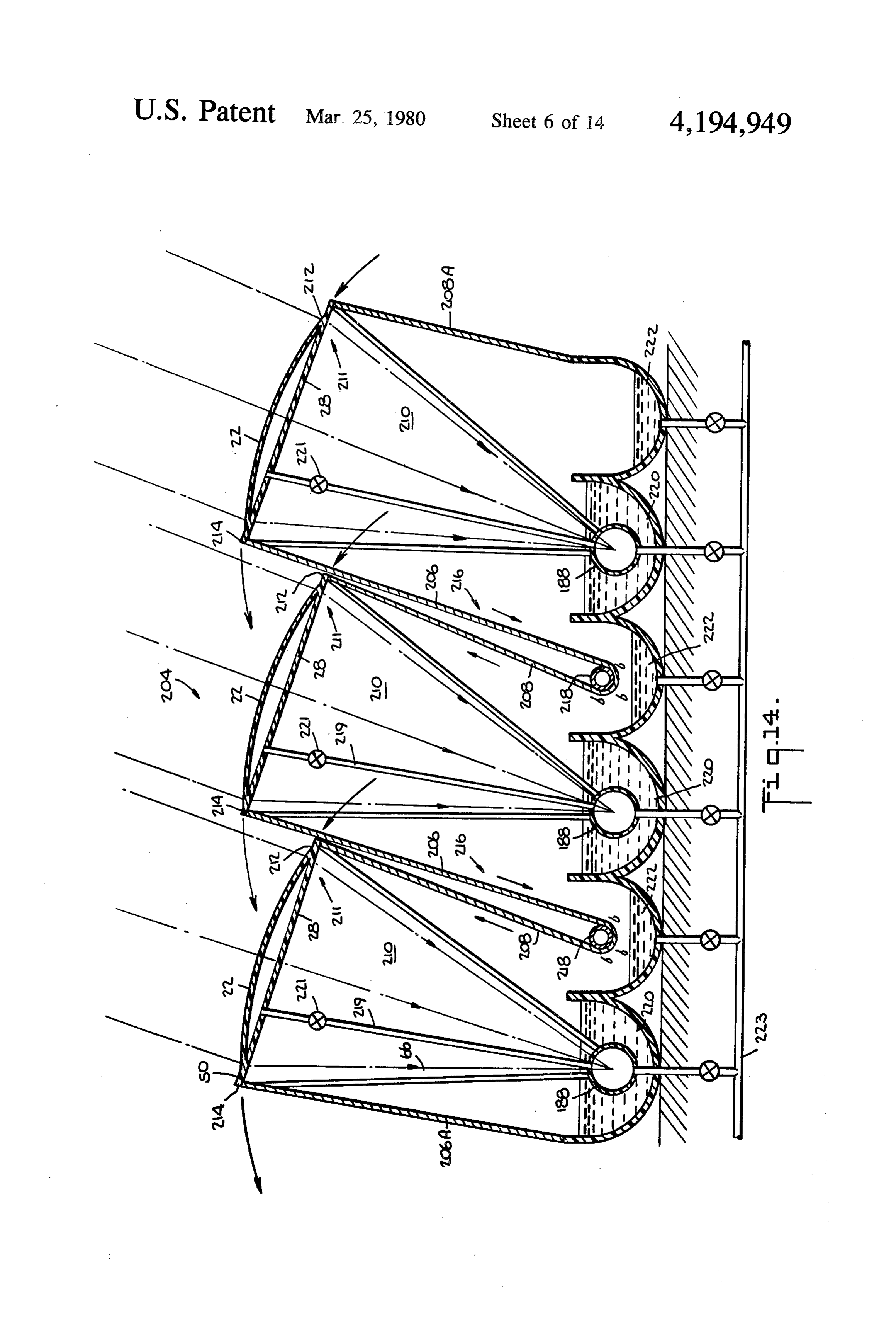
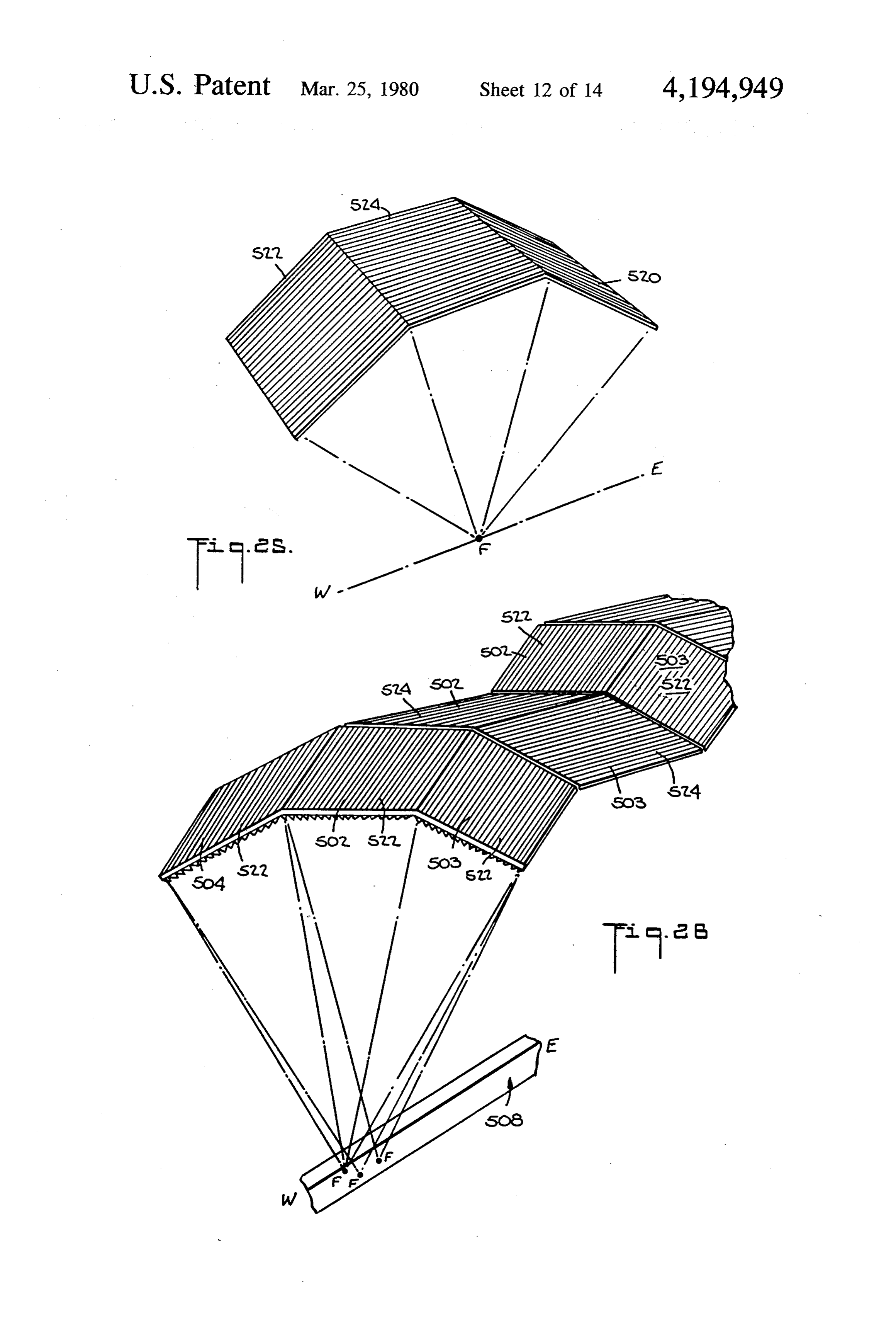
FIG. 14 is a schematic cross-section diagram of a FIG. 26 is a schematic perspective diagram of a com composite system for distilling water comprising indi- 65 posite lens system with the lenses positioned and angled vidual systems, each comprising a single, elongated, as shown in both FIGS. 23 and 25 to concentrate the movable fluid lens to follow the seasonal location of the solar energy in or on the collector both during the dif sun and a collector comprising a single fluid-carrying ferent times of year and different times of day;
Page 22scan →
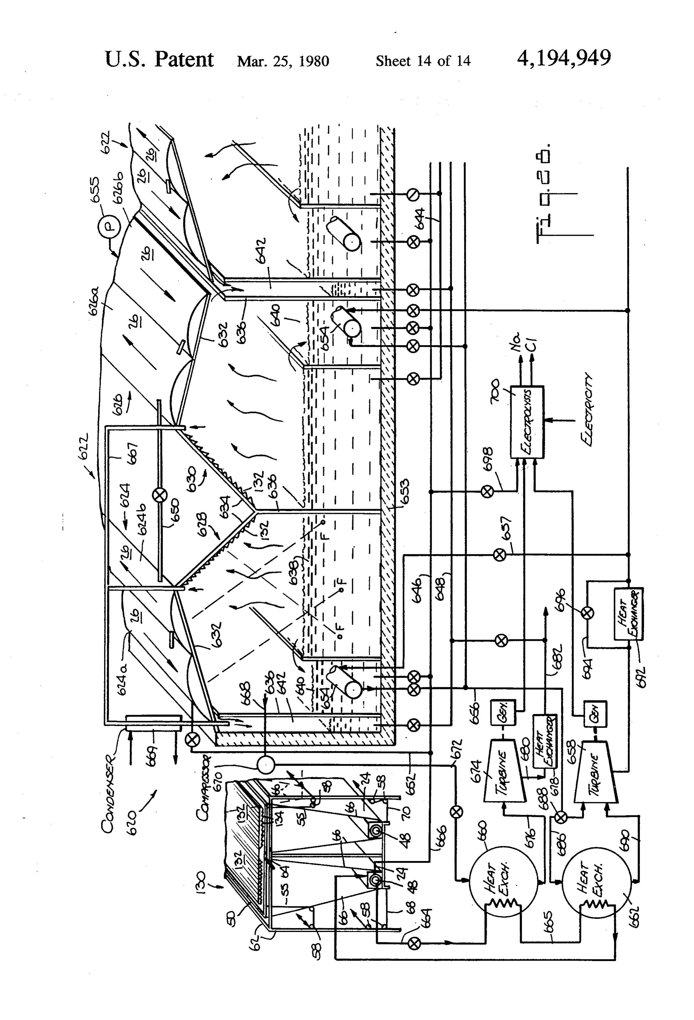
FIG. 27 is a schematic perspective diagram of a sys 55 in the direction of the arrows pivots lens 22 about tem comprising a central reflector located above a col axis 52 moving plate 26 towards the west. Movement of lector and adjacent concentrating reflectors, and a cen cables connected to the other end of frame 30 (not tral fluid lens located between the central reflector and shown) pivots lens 22 about axis 52 moving plate 26 collector, the reflectors being disposed to reflect solar towards the east. Thus, lens 22 is rotatable in the east energy through the central lens, the lens concentrating west direction to track the sun's hourly movement. the solar energy in a substantially continuous and linear Lens 22 and collector 24 are also rotatable in the north focus located on photovoltaic cells in the collector; and south direction about longitudinal axis 60 to track the FIG. 28 is a schematic perspective diagram showing sun's seasonal movement. Frame 50, in which is a system for substantially continuous distillation of 1 mounted lens 22, is pivotally mounted adjacent the ends water comprising a plurality of parallel distillation units of the lens to supporting frame 62 by members 64 (only each comprising two spaced series of fluid lenses of two one of which is shown) and pivot joints (not shown). parallel sets each, each unit having a central container Rigidly interconnected to frame 50 is collector 24 by for receiving preheated water to be distilled which is members 66. Frame 50 and collector 24 are rotatable as circulated through and discharged from the fluid lenses 15 a unit about axis 64 thereby maintaining the relative into the central container, adjacent containers being orientation between the collector and lens unchanged. provided to receive water to be distilled overflowing Cables 68 (only one of which is shown) are connected from the central container, and heat transfer means, to one side of the collector to pivot the lens and collec turbines, and a separate solar energy concentrator and tor towards the northerly direction and cables 70 (only collector being provided to generate electrical and/or 20 one of which is shown) are connected to the other side mechanical power from solar energy as well as produc of the collector to pivot the lens and collector towards ing additional distilled water. the southerly direction to a position such as the one shown in broken lines. Cables 68 and 70 are also would
DESCRIPTION OF THE PREFERRED around pulleys 58 to run the cables in a common direc EMBODIMENTS 25 tion towards drive means (not shown). The lens and In FIG. 1 is shown a solar energy collecting system collector are rotatable over a total angle of about 47 comprising a refringent fluid lens concentrator and a degrees during the year in the north-south direction. fluid-containing solar energy collector. System 20 com The drive means may comprise, for example, electric prises an elongated fluid lens concentrator 22 and col motors activated and controlled by sensors such as lector 24 in the form of elongated fluid-containing con 30 phototransistors or by, clocks, electric timers, or by duits. Elongated fluid lens 22 comprises solar energy computers. Automatic, semi-automatic or manual transmitting plates 26, 28, which are preferably separate means may be used to track the sun's location in addi pieces mounted in frame 30 and spaced to enclose solar tion to the one illustrated in FIG. 1 and described energy transmitting fluid 31. In the embodiment shown above. One system uses an electric motor whose shaft is in FIG. 1, upper lens plate 26 is convex and lower plate 35 turned by a small angle whenever the direct or focused 28 is planar. The respective sides 32, 34 of lens plates 26, sunlight hits a photocell or thermo-couple. Hydraulic 28 and the ends of the lens plates (not shown in FIG. 1) systems may also be used to move the lenses and collec are sealed to be fluid-tight in manners which will be tors. Other systems use a timer or a weight and pulley described hereinafter. Alternatively, means not shown device. Movement of the sun affects the electric output in FIG. 1 for adding and removing or circulating fluid 40 of the photocell to control the motor or the motor is 31 and air are provided in the sides and/or ends of the controlled by the timer to turn the shaft in small angular lens plates. Additionally, lenses may be longitudinally increments, or the weight and pulley device turns the and transversely (radially) juxtaposed and will also be shaft. As mentioned, such complete systems for moving described hereinafter. In the embodiment shown in the lenses and sensing the sun's position are known and FIG. 1, collector 24 comprises an outer elongated con 45 are not shown. Parts of systems used for tracking the duit 36 enclosing an inner elongated conduit 38, both sun's position are shown in the drawings. While daily or shown to be tubular in shape. Conduit 36 is placed in hourly tracking is preferred to enhance solar energy insulating container 40 and is surrounded by insulating collection, it is not required since the collector and lens material 42 except for a longitudinally extending open are generally oriented in the east-west direction. By ing 44 located above conduit 36. Opening 44 is closed 50 interconnecting and moving the lens and collector, the off by solar energy transmitting and heat insulating lens focus is always maintained at the collector regard plate 46. Plate 46 is suitably made of glass or plastic and less of season. The above-described tracking arrange the insulating material 42 is suitably a foam, such as ment substantially increases solar energy collection polyethylene foam. A sealing material such as, for ex since the system is always oriented in directions directly ample, silicone is provided between plate 46 and con 55 facing the sun, seasonally and preferably hourly. tainer 40 to seal the container fluid-tight. Collector 24 is As mentioned hereinbefore, the collector is located at located below lens 22 and the theoretical linear focus 48 the theoretical focus 48 of the lens 22 and in the embodi is located at or along the collector. The axis of the lens ment of FIG. 1, conduits 36 and 38 are solar energy (and of the system) is oriented along the east-west direc transmitting, the theoretical focus 48 being located tion. 60 within the inner conduit 38. Conduits 36 and 38 contain Frame 30 and lens 22 are supported by and pivotally heat-carrying fluids 54 and 56, respectively. Since the mounted in frame 50 to rotate about transverse axis 52 concentration of the solar energy will be greatest in the by members 53 and pivot joints (not shown). Cables 55 fluid within the conduit at which the lens theoretical are connected to opposed sides of frame 30 adjacent focus is located, i.e., in fluid 56 within conduit 38, fluid sides 32, 34 of the lens, at opposed ends of the lens (only 65 56 may be heated to a relatively high temperature and is one of which is shown) and wound about rollers or therefore chosen to have a relatively high boiling point, pulleys 58 to run the cables in a common direction for example, from about 150° C. to about 350° C. Such towards drive means (not shown). Movement of cables fluids may comprise by way of example and not limita 23 tion lubricating oils, glycerine, mineral oils, paraffin The fluid 31 in lens 22 may be communicated with oils, etc. Thus, during periods of sunshine, fluid 56 is one of the conduits in the collector 24 to remove heat heated to a temperature which may be in excess of 100 from the lens fluid, thereby maintaining it at a suitable . C., for example, 200° C., the precise temperature at temperature while utilizing heat from the solar energy tained depending on many factors such as the flow rate absorbed by the lens fluid to, for example, preheat the of fluids 54, 56, the diameters of conduits 36, 38, sun fluids circulating in conduits 36 and/or 38. intensity and position, insulation, heat exchange rates, In FIG. 1, collector 24 was shown to comprise tubu etc. Fluid 54 is selected to have a boiling point which is lar conduits 36, 38. However, the conduits need not be less than the boiling point of fluid 56, preferably at least tubular and in some instances other configurations are 50° C. less than the boiling point of fluid 56, and prefera 10 preferred such as for example, rectangular. A rectangu bly in the temperature range of from about - 60° C. to lar configuration may be desirable when the theoretical about 100° C. Such a fluid is suitably water. It is also focus has deviations. Providing a rectangular shape will preferred that fluid 54 have a low latent heat of vapori allow movement of focus 48 while still maintaining it at zation, for example, from about 20 calories per kilogram conduit 36. Focus 48 can be on the surface of conduit to about 270 calories per kilogram, and such fluids may 15 36, and in such a case, the surface of conduit 36 need not comprise by way of example and not limitation refriger be solar energy transmitting and is preferably darkened. ants, solvents, hydrocarbons, alcohol, etc. It is to be understood that the systems shown in the In operation, solar energy is concentrated in fluid 56 remaining figures and described hereinafter are longitu (chosen to be lubricating oil) within conduit 38 and dinally oriented in an east-west direction and faced raises the temperature of the oil to about 200° C. Since 20 towards the sun. It is to be further understood that the the focus to lens 22 is theoretically linear, fluid 56 will elongated lenses or lens system and the elongated col be continually heated as it traverses the linear focus. lectors and conduits thereof are arranged substantially Fluid 54 (chosen to be water) surrounds the oil and along parallel longitudinal axes. It is to be still further conduit 38, and is heated primarily by the oil primarily understood that it is preferred that the concentrators through conduction. Both fluids, oil and water, are 25 and collectors are movable and that means may be pro circulated at predetermined rates to obtain desired tem vided for moving them to track the seasonal and prefer peratures and may be used for different heat applica ably the hourly location of the sun. Movement of the tions. For example, the water may be heated to about lenses, however, may not be required where the lens 70° C. to 80° C. or more and used for space and hot focal length is short such that displacement of the focal water heating. The water may be heated to lower tem 30 line will be small from season to season and remain peratures and used, for example, in swimming pools. within the periphery of the inside conduit 38 of the The higher temperature oil may be used for applications collector. Manual, automatic or semi-automatic drive requiring higher temperatures including industrial ap means for effecting tracking movement of systems and plications or may be used merely to heat the water. /or lenses on a seasonal or hourly basis are known. Since the temperature of fluid 56 increases as it tra 35 While only part of a single lens is shown in FIG. 1, it is verses the lens focus, fluids at many different tempera to be understood that many lenses may be longitudi tures are realizable by providing taps for fluid outlet nally and transversely located.
and/or inlet at different points along the focus. Fluid 54 Conduits 36 and 38 in FIG. 1 may both include may be evaporated and the vapor or superheated vapor opaque heat conducting surfaces and the lower part of used to produce mechanical power in expansion means 40 the surface of either conduit 36 and/or conduit 38 is such as motors, turbines and engines which, in turn, preferably darked by black paint or the respective con may generate electricity. Preferably, a closed system duit or conduits are preferably provided at the lower (not shown) is employed in which the condensed fluid is half of the surfaces thereof with black metallic sheets to returned to collector 24. In such applications, fluids prevent transmission of solar energy and to enhance Such as refrigerants, solvents, hydrocarbons, alcohol, 45 heat absorption from the solar energy. etc., and the like may constitute fluid 54. Additionally, plate 46 provides a greenhouse effect in As mentioned hereinbefore, a serious drawback of the collectors, and container 40 is preferably made of Solar energy systems in general and known systems in insulating material to further reduce heat losses. The particular relates to the storage of energy during peri reduction in heat loss is especially important during ods in which there is no sunshine or the intensity thereof SO periods of no or reduced sunshine. However, as will be is low, as for example during the night or during periods described more fully hereinafter, plate 46 may be elimi of cloudy weather. Heat is stored for use in those peri nated when it is not desired to retain heat at the lens ods in fluid 56 which is heated during normal system focus such as when photovoltaic cells are located operation to a temperature which is at least about 50 C. thereat. It is preferred that the theoretical focus of the higher than the temperature of fluid 54. Therefore, even 55 lenses be located at the inner fluid to further reduce heat when fluid 56 is not being heated by solar energy or losses since the outer fluid will act as an insulator. The being heated at a reduced rate, it stores heat and will solar energy transmitting tubes in FIG. 1 are preferably continue to supply heat to fluid 54 due to the tempera made of colorless and transparent glass or plastic and ture difference between the two fluids. Preferably, the the tubes which need not transmit solar energy there circulation of fluid 56 is stopped for those periods. Fluid 60 through are preferably metal, preferably steel, copper 56 continues to transfer heat to fluid 54 until the differ or aluminum, and all are preferably darkened at their ence in the temperature of the two fluids is relatively lower surfaces.
small. The time that fluid 56 will transfer and/or store The area of the collector surfaces may be much heat depends upon the initial temperature of fluid 56, smaller than the area of the concentrators and may be the difference in temperatures between the fluids, the only from about 1% to about 10% of the area of the volumes of the fluid, the characteristics (specific heat, conventional flatplate collector, thus reducing the heat boiling point, latent heat, etc.) of the fluids, the use to losses accordingly. As less material is required in the which fluid 54 is put, etc. collector, the cost will be reduced.
Page 24scan →
The collector systems may comprise a number of by the fluid and heat it. Some of the infrared rays will be conduits other than two and configurations other than absorbed by the lens plates which will be heated and in tubular, and the lenses and lens systems may be other turn partly heat the fluid. Part of the solar energy will than that shown in FIG. 1. be reflected by each plate, part of the reflected solar Referring now to FIG. 2-8, the fluid lenses may have energy being reflected towards the inside of each plate configurations other than that shown in FIG.1. In FIG. into the lens to also be partly absorbed by the lens fluid. 2 is shown planar-convex lens 22 comprising curvilinear Little of the luminous rays in the wave length range of upper plate 26 and spaced planar lower plate 28 enclos about 0.25 to about 0.7 microns will be absorbed in a ing solar energy transmitting fluid 31. The plates may be transparent and colorless lens fluid and transparent and economically made of glass or plastic and are joined at O colorless lens plates. For certain applications, it is desir sides 32, 34 in a fluid-tight manner as by welding or able that the absorption of infrared rays be minimized, gluing. Alternatively, lens 26 may be extruded with for example, where it is desired to produce as much heat sides 32, 34 integrally joined. The ends of the lenses may as possible at the lens focus. In other applications, it may similarly be glued, welded or extruded. FIG. 3 shows a be desirable to heat the lens fluid and/or provide as little bi-convex lens 78 comprising spaced curvilinear plates 5 heat as possible at the lens focus while transmitting as 26. Lens 78 is formed as described for lens 22. This much as possible of the luminous rays such as, for exam configuration may reduce the focal distance to a collec ple, when photovoltaic cells are located at the lens tor. Lens 80 shown in FIG. 4 comprises curvilinear focus. In the former case, the distance between the lens upper plate 82, spaced planar lower plate 84 and side plates is minimized, for example, to about 1 inch at the wall 86. Lens 80 is economically formed from a bulb of 20 point of maximum separation of the lens plates, and the glass or plastic as by blowing as, for example, in the lens fluid is chosen to absorb at ambient temperature a manufacture of glass or plastic bottles. The lenses minimal amount of infrared rays and preferably has an shown in FIGS. 2-4 when used in solar energy systems index of refraction of at least 1.35. Fluids such as hydro are supported by suitable frames and structural mem carbons, mineral oils, solvents, solutions such as salt bers. For example, lens 80 is supported by frame 88 25 water, etc. are transparent, colorless and absorb sub shown in FIGS. 5 and 6. As there shown, a plurality of stantially less infrared radiation than water. When used, lenses 80 are longitudinally juxtaposed at ends 90 and the fluids are preferably chosen to be non-corrosive to supported by longitudinal support stringers 92 and glass and plastic and to have a suitable boiling tempera transverse support stringers 94. The lenses may be se ture. Some fluids having a high index of refraction and cured to the frame by, for example, adhesives. As 30 low absorption of infrared rays such as trichloroethy shown in FIGS. 5 and 6, the theoretical focus 96 of the lene and toluene are corrosive to plastics such as acrylic lenses is at and along collector 98. Means in the form of plastics. When using such corrosive fluids, the lens openings 100 are provided to add and remove fluid 31 plates exposed to the fluid are covered by sheets such as and/or air and the openings may be communicated by, Teflon or coatings of epoxy such as Lucite RD which for example, tubes 102 to provide for circulation of the 35 are not corroded by the lens fluid. In the latter case, the fluid. The openings may be provided in other locations, distance between the lens plates is maximized, for exam for example, as shown in FIGS. 2-5 and referenced by ple to about 4 inches at the point of maximum separation 100. As mentioned hereinabove, the plates forming the of the lens plates, and the fluid is chosen to absorb at lenses may be integrally extruded or blown or may ambient temperature a maximum amount of the infrared comprise separate plates joined as by welding. Refer rays while still being transparent and colorless. The ring now to FIGS. 7 and 8, upper cirvilinear plate 26 degree of absorption of infrared rays is also dependent and lower planar plate 28 are separate pieces and are upon the material used for the lenses. For example, for joined in a fluid-tight manner by means of frame 104. low absorption, waterwhite glass with about 1.5% ab Frame 104 comprises two longitudinal grooves 106, sorption or plastic with a similarly low absorption may 108. The upper groove 106 is curvilinear and sized to 45 be used with a lens fluid such as a salt water solution. accommodate upper curvilinear plate 26 while the Where a high degree of absorption of infrared rays is lower groove is linear and sized to accommodate planar desired, for example, in electricity-producing applica plate 28. The edges of the respective separate plates are tions wherein the solar energy is focused on photovol inserted into the respective grooves along with sealing taic cells, glass and plastic lenses with lens fluids having material 110. The ends of the plates are similarly joined. 50 an infrared absorption of, for example, 20% may be The material 110 may comprise a gasket or similar flexi used. It is preferred that water be used in the latter case ble piece and/or or deformable material such as silicone where it is desired to absorb infrared radiation. In cer to form fluid-tight joints. Thus, the lenses according to tain locations, an antifreeze product is added to the the invention in which two independent plates are water to prevent freezing. If water is used in the collec joined or the lenses are extruded or blown, are rela 55 tor, an antifreeze product is also added to the collector tively easy to manufacture and are relatively inexpen water. With water used as the lens fluid and the larger sive. The required radius or curvature of the curvilinear distance (for example of 4 inches) separating the lens convex plate and the focal distance to the collector plates, there will be an increased absorption of the infra from the lens will depend on the width of the plates, the red rays by the lens fluid and a corresponding increase maximum distance between the plates and the refrac 60 in heating of the lens fluid. The heat in the lens fluid can tory index of the fluid between the plates, and fluids be recuperated in heat exchangers and used for heating with higher refractory indices shorten the required and/or preheating the collector fluids as described here radius and focal distance. inbefore. The heat may also be used to heat water for Depending on the lens fluid used and the distance domestic use or for other uses, or to heat buildings, or to between the lens plates, a percentage of the infrared 65 produce electricity by superheating low boiling temper rays in the wave length range of about 0.7 to about 4 ature fluids and expanding the vapor in expansion microns impinging on the lens will not pass through the means such as turbines or engines. Since the lens fluid lens. Some of the infrared rays will be absorbed directly permits most of the luminous rays to be transmitted 25 therethrough, electrical generation by the photovoltaic such systems are shown in FIGS. 13, 14, 15, 16, 20 and cells will be essentially undiminished while the lens 21.
fluid is being heated and the heat being used as men The system 160 shown in FIG. 13 comprises a plural tioned for heating and/or production of additional elec ity of sub-systems 162, each employing a three lens tricity. Thus, the invention provides a highly economic arrangement 164. Each lens system 164 is supported combination of simultaneously generating heat and above an elongated, central, channel 166 and parallel, electricity. elongated, side channels 168 such that the central part Referring now to FIG. 9, system 70 is made up of of the lens system is above the central channels and the panels 71 of fluid lenses 22. Each panel comprises four outer longitudinal edges of the outer two lenses are fluid lenses 22 arranged transversely and longitudinally 10 above the side channels. Each lens is inclined and the adjacent one another. The panels are supported and bottom lens plates 28 are planar. The water 170 to be rotatable to track the sun seasonally and hourly. Frame distilled is filled in the central channel to a predeter 50 is supported on shafts 64 which are rotatably con mined height. Within channel 166 are located the elon nected to frame 62 at opposite ends of the frame by 15 gated foci F of the lenses, preferably at different loca means such as bearings. One end of one of the shafts 64 tions and different heights, the different heights corre is connected to drive means (not shown) such as an sponding to different water depths in channel 166. In electric motor. Lenses 22 and frame 50 are rotatable FIG. 13, lens fluid 31 is advantageously salt water. The about longitudinal axis 60 by rotating shaft 64 to track solution of salt (NaCl) dissolved in water absorbs less the sun seasonally. Frame 30 is pivotally connected to 20 to infrared rays than water alone. Thus, where it is desired frame 50 by members 52 and is movable with lenses 22 salt/water reduce absorption of infrared rays in the lens fluid, a about the common transverse axis 53 to track the sun's solution is preferably used as the lens fluid. position as described for FIG. 1. When desalinating sea water, the sea water is preferably used as the lens fluid and preferably is also introduced
In FIG. 10 is shown a plane refringent element 126 preheated comprising a rigid frame 128 surrounding a sheet or into the container holding the water to be plate of plastic or glass material 130 in which are 25 distilled. Valving is provided in the conduits to control formed by impressions or molding concentric, closely draining and to regulate circulation of the fluids. In operation, the water 170 to be distilled is heated due to spaced rings or microprisms 132 whose pitch, for exam the ple, corresponds to about 3 to about 4 microprisms per 170 solar is energy concentrated at foci F and the water vaporized. The vapor strikes the lower plates 28, millimeter. The plane refringent element 126 acts like a 30 is condensed thereon plane Fresnel lens. Solar energy striking the refringent charged at or droppedand flows therealong to be dis element 126 is concentrated by the microprisms into a channel 168. The interiors ofthetheedges from thereof into side fluid lenses are com theoretical point focus (not shown). Refringent element municated with the interior of channels 166 by conduits 126 may be positioned longitudinally juxtaposed as the 177 (only one set of which are shown) as well as being fluid lenses in FIG. 5 and/or transversely juxtaposed as 35 intercommunicated. Heat exchange means 179 may be the lenses in FIGS. 9 and 13. The system may be ar provided inside channel 166, particularly for transfer ranged so that the point foci of lenses 126 are located ring heat from the condensed water in channel 168 to within or at the surface or conduits 36 and 38, the series the water in channel 166. The water in the fluid lenses of discrete point foci along a length forming in effect, a is circulated through the lenses and channels. In this linear focus composed of discrete point foci. 40 way, the heat released by condensation of the vapor is System 130 of FIG. 11 is shown employing elongated transmitted through plates 28 to the water in the lenses refringent elements 132 having longitudinal micro and the heat absorbed by the water in the lens from the prisms 134 acting as longitudinal Fresnel lenses. The condensing vapor is returned to the system in the chan lenses 132 and collectors 24 are arranged so that the nels. Thus, the water to be distilled may be heated or linear focus of a column of lenses is located at a respec 45 preheated. The lenses 22 are arranged so that the foci F tive collector as described for FIG. 9. The lenses and remain within channels 166 regardless of the seasonal collectors are interconnected and movable as the sys and daytime location of the sun, the foci moving along tems shown in FIGS. 1 and 9. the paths indicated in channel 166 by the broken lines. FIG. 12 shows an arrangement for three conduits in Thus, the foci will not be displaced outside channels 166 which the inner conduit 139 is enclosed by intermediate 50 and it is therefore not necessary to provide means to conduit 141 which in turn is enclosed by outer conduit move the lenses to follow the location of the sun. Heat 36. Providing three conduits permits use of three differ in the distilled water may also be utilized to preheat or ent fluids, allows for use of the fluids at varying temper heat the water to be distilled. The distilled water may atures for many different applications and allows for a only be a few degrees less than the vapor temperature. larger displacement of the focal line. 55 The recovered heat may also be used for other purposes The present invention may be utilized for many en and the lens fluid and/or condensate can be circulated ergy applications as described hereinbefore and may through heat-exchanging means to remove the heat also be advantageously used to distill or otherwise treat therefrom. This is significant because the latent heat water by evaporation and condensation thereof. Typi required to vaporize the water 170 of about 540 calories cally, the water is seawater or brackish water and is to 60 per gram in addition to the sensible heat are released by be desalinated, or water or a liquid containing minerals condensation of the vapor and are substantially recuper or other substances, or water such as industrial waste ated from the condensate and substantially returned to water or polluted water which is to be purified and the system by the circulated water in the lenses upon distilled. The refringent concentrators and collectors which the vapors condenses. This latent heat and the are arranged in systems operative to distill water, pref 65 sensible heat are substantial and would otherwise be erably recovering the heat of condensation and prefera lost. This results in much higher efficiency of the system bly recovering heat in the condensed water and dis compared with solar stills where channels filled with charged brine as described hereinafter. Embodiments of water to be treated are covered with only glass or plas 26 tic plates or sheets which receive the solar rays. Circu densed water flows down side panel 208; and side panels lating the water in the lenses also cools the lower lens 206, 208, when cooled by the outside environment, will plates 28 thereby assisting condensation thereon. Con provide additional condensation of vapor which will duits 175 and 176 are provided for filling and emptying flow down panel 206 as well. The system remains en the respective channels. The water 170 to be distilled closed upon movement of the lens as follows. If the may be held between predetermined heights by a float lenses are rotated counterclockwise, interior side panels system comprising float 178 and relays 180 and 182. 206 move downwardly and interior side panels 208 Movement of the float activates respective relays to move upwardly about tubular members 218. The exte start and stop a pump or motor valve (not shown). A . rior side panels 206a and 208a are secured to the sides of similar arrangement may be used in side channels 168 or 10 respective channels and are made of an expandable a gravitational drain arrangement may be employed to material. Lenses 22 and collector 188 are communicated maintain the height of distilled water in the side chan by conduits 219 and valves 221 (only one set of which is nels between predetermined heights. The respective shown). The water in the fluid lenses may thereby be channels are communicated to provide approximately circulated in collector 188. In this way, the heat re equal levels in each of the respective channels. Advan 15 leased by condensation of the vapor is transmitted tageously, the channels are made of concrete or asbes through the plate 28 to the water in the lenses and the tos cement and are preferably insulated on the outer heat absorbed by the water in the lens from the con sides. Means other than the lens itself may be used to densing vapor is returned to the system. Thus, the water condense the vapor such as substantially smooth prefer to be distilled may be heated or preheated and fluids in ably planar plates located below the lenses 164. In such 20 the collector may be heated or preheated. Heat in the a case, the lens fluid may not recover substantially all of distilled water may also be utilized to preheat or heat the latent heat unless the plate is proximate thereto. the water to be distilled or fluids in the collector by Alternatively, means associated with the plate may be means of conduits 223 (only one set of which is shown) used to recover the latent heat. and heat exchange means, and circulation of fluid there The system shown in FIG. 13 is substantially en 25 through or elsewhere. The distilled water may only be closed by the channel panels to reduce heat loss. The a few degrees less than the vapor temperature. The recovery of the latent heat of the condensing vapor by recovered heat may also be used for other purposes and the lens fluid and the recovery of the sensible heat in the the lens fluid and/or condensate can be circulated condensed water assist in providing a continuous opera through heat-exchanging means to remove the heat tion system since heat losses are reduced. Additionally, 30 therefrom. Of course, whether conduits 219 or conduits as mentioned, by removing from the lens fluid the heat 223 or both are used will depend upon the lens fluid of condensation recovered by it, for example, by circu used, the fluid used in collector 188 and the arrange lating it in channels 166, the lens fluid will be cooled, in ment of heat exchange means. turn cooling the lower lens plate and assisting in con Referring now to FIG. 15, a portable water distilla densing any vapor impinging thereon. As described 35 tion system 280 is shown comprising single vessel 306 hereinbefore, the lens fluid will be heated by direct and holding the water 170 to be distilled. The system is indirect absorption of infrared radiation and by heating easily assembled and disassembled. Lens 282 is made of of the lens plates, and this heat may also be recovered flexible solar energy transmitting material such as clear from the lens fluid. The heat recovered from the lens plastic and forms an enclosure 286 when inflated by a fluid and condensed water may be used to preheat 40 fluid, advantageously water, which is introduced and water to be distilled before entering channel 166 or to removed and/or circulated by means including inlet 288 preheat and heat the water to be distilled in channel 166 and outlet 290. Air is also removed and fluid introduced by heat exchange means. The efficiency of the system through said means. Also, fluid and Fresnel (circular or can be further increased by recovering the heat con longitudinal microprisms) lenses as described hereinbe tained in the brine discharged from channel 166 from 45 fore may be used. Lens 280 is supported by frame 292 of time to time. The heat which is recovered from the metal or other suitable material which comprises upper condensing vapor, the condensed water, the brine and frame members 294 and side support members 296. The the lens fluid can be used for other purposes such as upper ends 297 of the side support members 296 are producing electricity by superheating and expanding pivotably connected to the upper frame members 294 as fluids having low boiling temperatures and low heats of 50 by bolts 298 such that each of the side support members vaporization. The water distillation systems described is pivotable about the bolts in the directions indicated hereinafter operate in similar manner and description by the arrows. Means such as indentations 300 are pro thereof will therefore be more limited. vided in platform 302 to secure in the lower ends 304 of In FIG. 14, an expandable material forms the side the side members in selected positions. Alternatively, a panels 206, 208 of each compartment 210 of the system. 55 platform is not used and ends 304 may be secured in the Advantageously, the material is of plastic. Opposed ground or otherwise. Pivoting of side members 296 ends 212, 214 of adjacent side walls 208,206 are secured adjusts angle A at which lens 282 is inclined. The elon to respective sides of lenses 22. Adjacent interior side gated vessel 306 advantageously collapsible and made walls are of one piece and are advantageously formed as of lightweight plastic is hung from frame members 294 a single sheet 216. Sheet 216 is wound partially about 60 below the central part of elongated lens 282 by cables or the circumference of tubular members 218 which ex rope 308. Hinges 310 are provided to secure the cables tend along longitudinal axes parallel to those of the to the vessel. Adjustment of angle A and movement of channels 220, 222. The tubular members are secured by cables 308 permit the lens focus to be positioned in means (not shown) to maintain sheets 216 as side walls vessel 306 during different seasons. A collecting vessel 208, 206 as shown. The lower sides 211 of lenses 22 65 314 is located below vessel 306 and below the lower terminate above channels 222. The evaporation and inclined end 316 of the lens 282. Vessel 314 advanta condensation of the water proceeds as described herein geously collapsible and made of lightweight plastic is before. In addition to the system being enclosed con also hung from upper frame members by cables or ropes
Page 27scan →
308 and hinges 310. Vessel 314 is inclined preferably by means of photovoltaic cells. Referring to FIG. 17, along the longitudinal direction to assist in draining photovoltaic cells 398 made of silicon or cadmium sul treated water therefrom by means such as valve 317 in fide or other materials are disposed in the interior of outlet 318. Port 320 is provided in vessel 306 for filling inner fluid-carrying conduit 400 shown advantageously and emptying. Distillation of water 170 by heating of to be of rectangular cross-section. The theoretical focus the fluid in conduit 312, advantageously water, and 402 of the lens is at the cells and preferably on the outer evaporation of the water, condensation of the vapor on surface thereof. The cells may be juxtaposed in series the lens and collecting of the condensate proceed as and also in parallel in the theoretical focus 402 in linear described hereinbefore. Expandable side panels 320 or spaced if the theoretical focus 402 is a point focus. may be provided to enclose the system and allow for 10 The concentrated luminous rays are converted to elec movement of lens 282 as described hereinbefore and tricity by the cells while the heat absorbed by the cells may be used to form collecting bags as shown in FIG. from the infrared rays is removed by the circulating 14. Means are provided to indicate the water levels in fluid 404 and also by the fluid 406 circulating within the the vessels 306, 314 such as vertical transparent glass or outer conduit 408. The removal of heat can be con plastic tubes 322,324 located outside side panels 320 and 15 trolled by the size of the conduits 402, 406 and by the connected by tubing with the bottoms of the vessels. volume and rate at which the fluid is circulated. Prefer In FIG. 16 is shown another embodiment of a porta ably fluid 404 is substantially electrically non-conduc ble water distillation system 330 which is easily assem tive such as air or other gases and liquids. Means (not bled and disassembled. System 330 comprises planar shown) are provided for connecting the cells in parallel Fresnel Lenses 126 of the type shown in FIG. 10 having 20 or series and for removing the generated electricity. If concentric microprisms causing the solar energy to be fluid 404 is electrically conducting, means (not shown) concentrated at point foci. A longitudinal Fresnel lens are provided for electrically insulating the cells and the or lenses may also be used. Lenses 126 are longitudi means for interconnecting the cells and for removing nally and transversely juxtaposed to form a composite the generated electricity. Conduit 402 has at least its lens assembly of six Fresnel lenses which is inclined 25 upper surface made of transparent material if the theo with respect to the horizontal, six being chosen for retical focus 402 is linear or transparent apertures may purposes of illustration. The lenses are formed into an be provided above the cells if the theoretical focus 402 assembly by, for example, securing them as by adhe is at a point. The upper part of outer conduit 408 is also sives to a solar energy transmitting glass or plastic plate transparent. The details of inner and outer conduits 332 which, in the case of plastic, may be folded along 30 have been described hereinbefore. flexible partition lines 334. Each Fresnel lens may be As mentioned hereinbefore, concentrating the lumi about 9 inches by about 7 inches and are presently avail nous energy of the sun with a concentration of up to able at a cost of about $0.40 each. The point foci of the about 100 permits electricity to be generated at up to lenses are located in the water to be distilled in flexible about 100 times more power while the increased heat container or bag 336 made of plastic or other pliable 35 energy is dissipated and removed by the fluids in the material. Flexible container or bag 338 made of plastic conduits. As described hereinbefore, the amount of heat or other flexible material located below and extending produced at the photovoltaic cells may be reduced by beyond container 336 is used to collect condensate from absorption of infrared radiation in a fluid lens. This will plate 332. The lens assembly and containers are sup increase the efficiency of the cells while reducing the ported by support assembly 340 comprising pairs of legs 40 heat dissipating requirements of the collector. The heat 342, 344, frame 346 and platform 348. The legs are piv absorbed in the lens fluid may be recovered as described otably connected to frame 346 as described for FIG. 15 hereinbefore. Electricity may be generated in conjunc to adjust the angle of incline of the lens assembly to tion with other uses of solar energy. For example, using follow the seasonal location of the sun. The containers a dual fluid carrying collector, photovoltaic cells may or bags have side panels 350, 352 which extend upwards 45 be inserted therein as just described and electricity gen to plates 332 to form an enclosed system as described erated while the heat energy is being used to heat a hereinbefore. An opening is provided in side panel 352 structure. Additionally, the electricity generated may at the lower side of plate 332 to allow the condensate to be used to electrolyze water and/or salt to produce drop into the collector bag 338. Means such as transpar hydrogen, sodium and chlorine. The hydrogen may be ent tubes 322, 324 connected to the bottom the the 50 used with carbon monoxide to manufacture methanol or containers are used to indicate water levels therein as with nitrogen of the air to produce amonia fertilizer and described for FIG. 15. The lens assembly, support as other nitrogen products such as nitric acid and urea. sembly and containers are easily assembled and disas Such electrolysis may be used together with the distilla sembled. THe foci located in the water to be distilled in tion apparatus of the invention. Still further in accor container 336 heat the water and cause it to evaporate, 55 dance with the invention, apparatus generating electric condensing on the bottom of planar plates 332. The ity using solar energy may be combined with hydro condensate moves along plates 332 and falls into con electric means having water storage means. Such a tainer 338. Depending upon location, production of combination provides for the production of electricity distilled water will be about 1 pound per hour for a at night, during periods of reduced sunshine, or during system as shown in FIG. 15 having a lens surface area of 60 peak demand periods by the hydroelectric means while 10 square feet (about 1 square meter). This production the solar energy system produces electricity during of distilled water is without recovering the latent heat periods of sunshine. The solar energy system may be of condensation. Production of distilled water could be provided as a floating installation on the reservoir and about eight times larger if the latent heat of condensa thereby not require additional land. tion is recovered. As mentioned hereinbefore, portable 65 As mentioned hereinbefore, it may be advantageous systems can be used at Sea or in desert areas. in some instances to eliminate the plate 46 of FIG. 1 According to another aspect of the invention, the used to produce a greenhouse effect in the collector, concentrated solar energy is used to generate electricity Referring to FIG. 18, system 410 is shown comprising 28 bi-convex fluid lens 78. Collector 414 does not include a preheat water introduced into channel 166, for example plate such as plate 46 of FIG. 1 so that heat from the to 40 C. As a result, almost no condensation occurs at infrared rays is not retained in the collector. Addition such location. Highly efficient Fresnel lens 132B is ally, photovoltaic cells 398 and transparent conduits 36, inclined at a steep angle with the horizontal facing 38 are only partially located in container 412 of collec north, and is focused inside the inner conduit in collec tor 414 to further disperse heat produced by infrared tor 172 which is of the two conduit type. Collector 172 rays focused at the cells. Location of the conduits and and Fresnel lens 132B are connected and the lens is cells only partially in insulating material 42 of container supported as described for FIG. 1 so both are movable 412 provides a wide-angle exposure of the photovoltaic to track the seasonal and hourly location of the sun. cells to the surface of the fluid-lens. Other details of 1 Preferably, flexible sheets 452, 453 are provided and collector 414 are similar to those described hereinbe attached on one side to the support for the Fresnel lens fore. Elimination of plate 46 and its associated sealant 132A and on the other side at the support structure for and the reduction in insulation used reduce the cost of the fluid lens 22. The inner conduit 38 carries a high the collector while dispersing heat produced by the boiling point fluid which is capable of being heated to a infrared rays. The lens fluid and the distance between 15 high temperature of, for example, 200 C. This, in turn, the lens plates 26 are chosen to maximize absorption of heats the lower boiling point fluid in the outer conduit the infrared rays in the lens. The lens and collector are to, for example, 80 C. Because of its steep angle, be movable as described for FIG. 1. The bi-convex fluid cause it is not cooled by a fluid as is a fluid lens, little lens 78 with the convex plates 26 shortens the lens focal vapor condenses on lens 132B. Fluid lens 22, having a distance to collector 414. 20 lower efficiency than lens 132B, is inclined at a slight Fluid lenses having upper and lower plates are gener angle with the horizontal facing south of, for example, ally of large size and consequently have long focal 15 which is sufficient to cause condensate to flow along lengths which are generally longer than the width of lower plate 28 and be discharged into channel 168. Lens the plates. Longitudinal Fresnel lenses having longitu 22 is focused directly in channel 166 so that its focus dinal microprisms are generally of smaller size and have 25 will be in water 170 regardless of the sun's seasonal and shorter focal lengths. Since the longitudinal micro daytime location. A substantial amount of the vapor prisms decrease in height toward the center of the lens, will impinge on lens 22 because of its location. The the lens width is limited. Also, the width of the glass or Fresnel/fluid lens combination shown in FIG. 20 has plastic sheets used for the Fresnel lenses is limited. This the following advantages. Using a plurality of lenses, can ben used to great advantage. For example, plate 46 30 and collectors and foci at varying water depths permits or conduit 426 may be eliminated but the greenhouse heating the water to different temperatures at different effect retained by reducing the distance between the depths to set up currents which assist in overall water lenses and the collector in an enclosed system. heating and evaporation, thereby increasing system FIG. 19 shows a combination of a central fluid lens efficiency. Employing Fresnel lenses to heat the water 200 with four adjacent Fresenl-type lenses 201 and 204, 35 while providing a fluid lens on which the vapor con each having engravings angled to direct the solar rays denses permits recuperation of the heat of vaporization to a common elongated focus 208 which is also the by the lens fluid while still employing the more efficient focus of the central fluid lens. The lens system may be movable Fresnel lenses. The fluid lens is not movable interconnected with collector 205 and be made movable since a suitable angle of inclination must be maintained to track the position of the sun as described herein for the condensate to flow along the bottom plate of the above. The lens system may comprise two Fresnel-type lens. The focus of lens 22 will always be in channel 166 lenses instead of four. Also, the lenses may be arranged regardless of season. Using a two conduit collector 172 longitudinally and transversely as shown in FIG. 9 to at the focus of the efficient Fresnel lens and including a increase substantially the concentration of solar energy, high boiling point fluid permits raising the temperature particularly for use in the production of electricity with 45 of that fluid to about 200° C. whereby heat may be photovoltaic cells. stored as described hereinbefore and used during the Fluid lenses are larger than Fresnel lenses and are less night. Locating the focus of lens 22 directly in the chan efficient absorbing and reflecting more solar energy nel heats up the water quickly and provides heat to the than Fresnel lenses. Thus, a system comprised entirely water 170 during periods of sunshine. During periods of fluid lenses is generally less efficient than a system 50 without sunshine (and even during periods of sunshine having only Fresnel lenses or at least one Fresnel lens when heat is removed from the lens fluid), the lens fluid combined with at least one fluid lens. Further in accor is cool and will provoke greater condensation of vapor. dance with the invention, systems are provided which This combination permits continuous operation, the include fluid and Fresnel lenses. Such systems can be focus of lens 22 directly in the channel providing evapo used to great advantage in distilling water where fluid 55 ration of water during periods of sunshine and collector lenses increase overall efficiency by recovering the heat 172 in which fluids are heated to 200° C. in the inner of vaporization of the water being distilled. Referring to conduit and 80 C. in the outer conduit storing heat and FIG. 20, such a system 450 is shown. System 450 com providing for evaporation of water during periods with prises fluid lens 22 and Fresnel lenses 132A and 132B. and without sunshine assisted by a lower lens plate 28 Each lens has a different focus within channel 166 con 60 cooled by the lens fluid.
taining the water 170 to be distilled. Channel 166 is Another embodiment for distilling water similar to trough-shaped to provide varying depths of water and the apparatus shown in FIG. 20 is shown in FIG. 21. the different foci are located at different depths. A nar However, in FIG. 21, two sets of double plate fluid row Fresnel concentrator 132A is positioned over the lenses are provided. One set of lenses 22A is inclined area in channel 166 in which water to be distilled is 65 south at, for example, 15 with the horizontal and has a introduced which is referenced by 451. Due to the sin smaller distance between plates of, for example 1 inch at gle conduit in collector 188, and the location and size of the point of maximum separation. Such plates will have lens 132A, collector 188 and lens 132A are used to sloped, cooled bottom plates to allow the vapor to con 29 dense on such plates and to flow toward and be dis lector 414, photovoltaic cells 398 being disposed therein charged into channel 168. Another set of lenses 22B as in FIG. 18. However, conduits 36, 38 are not en contains circulating lens fluid having preferably a boil closed to provide the greenhouse heating effect. In ing temperature over 200 C. and high infrared ray FIG. 22, the conduits are disposed entirely in insulating absorption characteristics. This fluid is circulated from container 412A. However, the wide trough-like open the lens system into the inner conduits 38 of a series of ing 413 in the container which is not closed off reduces perferably metallic interconnected collectors 172, greenhouse effect heating. Other collectors as described 172A, 172B, 172C. A plurality of interconnected collec hereinbefore may be used where a greenhouse effect is tors is provided to increase the overall collector surface desired. Both lenses are preferably movable to track the area in channel 166. The inner conduits 38 are inserted 10 normal location of the sun. Lens 22 is supported as in outer conduits 36. Another fluid such as water flows described for FIG. 1 while lens 132 is supported below in outer conduits 36 about conduit 38. The fluid circu lens 22 in a manner similar to that in which collector lated in conduit 36 will be heated to, for example, 90° C. 414A is supported. Additionally, either lens may be to heat the water 170 contained in the vessel 166. The superposed over the other and two Fresnel or two fluid flow of the high temperature fluid in conduits 36 is 15 lenses may be used.
stopped during hours without sunshine and the fluid In FIGS. 23–26 are shown a combination of a central with high temperature is stored in the inner conduits 38 Fresnel-type lens or lenses and adjacent Fresnel-type and continues to heat the fluid in the outer conduits 36. lenses which concentrate the solar energy along a sub The outer conduits 36 will in turn heat the water to be stantially common focal line substantially regardless of distilled during hours without sun. Lenses 22A with 20 season and time of day (FIGS. 25 and 26) without using cooled bottom plates 28 will condense the water vapor sun tracking equipment. Referring to FIG. 23, lens so produced and also during hours without sunshine, system 500 is shown comprising central elongated Fres and discharge the condensate into the channel 168. nel-type lenses 502 and adjacent elongated Fresnel-type During hours with sunshine, lenses 22A provide heat lenses 503, 504. The central lens may also be a fluid lens. for vaporization of the water to be distilled. In the sys 25 The lenses extend generally along the east west direc tem described above, and shown in FIG. 21, the lenses tion. The microprisms, referenced generally by 506, are need not be made movable to track the sun since the foci angled and the lenses positioned to bring the lens system of the lenses will always be in the vessel containing the focus in or on collector 508 regardless of season. By water to be distilled. As mentioned hereinabove, prefer way of illustration only, FIG. 15 schematically shows ably a salt/water solution and preferably sea water is 30 how the microprisms 506 may be angled to accomplish used as the lens fluid, and in the case of distillation of this. The central lens 502 is shown parallel to the earth's seawater, the seawater from the lens being introduced surface 510, but the entire system may be rotated so that into the vessel preheated. lens 502 is at an angle with the earth's surface, depend Solar energy systems may, according to the inven ing upon location of the system. For the system shown tion, be combined with heat pumps (either with a com 35 in FIG. 23, lens 503 will primarily concentrate the solar pressor or an absorption system). The combination energy during the time closely before and closely after could be used in air conditioning systems, refrigeration the winter solstice, lens 502 during the time closely Systems and/or as a heat storage system wherein the before the closely after the spring equinox, lens 504 heat pump provides heat when there is no or reduced during the time closely before and closely after the sunshine. A heat pump uses either air or preferably 40 summer solstice, lens 502 during the time closely before water as a source of heat or heat obtained from solar and closely after the fall equinox, etc. energy collected by the fluid or fluids in the collectors The focus F is located in or on collector 508 which described hereinabove to vaporize the circulating re comprises two adjacent transparent conduits 36 each frigerant. If water is used, a large reservoir is generally enclosing an inner conduit 38. In this way, even with required as the outflowing water is cooled to a low 45 lateral deviation of the focal line, it will still be located temperature and may freeze if the reservoir is a small in one of the conduits. Additionally, where the focal one. The heat obtainable from a heat pump depends on line may not be sharp, providing adjacent conduits the difference in absolute temperature between the heat permits the focal line to be partially located in a plural source used to vaporize the refrigerant and the con ity of conduits. A curved reflecting plate 512 is prefera densed refrigerant. The heat obtained by the heat pump 50 bly positioned below the conduits to direct any energy can be from two to five times higher than the power falling on it towards the conduits.
required in the compressor for the refrigerant. The heat Referring now to FIG. 25, it is preferred that the pump may be used to provide additional heat during Fresnel-type lenses located at the east and wast ends of hours without sunshine. The combination of the solar the system be angled with respect to the inner lens to energy system with a hydroelectric plant having a 55 better orient those lenses for morning and evening con water reservoir can be used to great advantage with a centration. For example, lens 520 at the east end is in heat pump, wherein the heat is obtained by the heat clined to face the sun in the moring and lens 522 at the pump from the water of the reservoir of the hydroelec wast end is inclined to face the sun in the evening. The tric plant. inner lens 524 is oriented to face the sun during the Lenses may also be combined so that the solar rays 60 middle of the day. This lens arrangement provides for pass serially through them. Such an arrangement can increased solar energy collection with using sun track shorten the focus of the lens arrangement and may pro ing equipment.
vide a sharper focus at the collector and is particularly In FIG. 26 is shown a composite lens system includ useful where the lens is focused on photovoltaic cells. ing adjacent lenses such as lenses 503 and 504 positioned FIG. 22 shows fluid lens 22 as described hereinabove 65 to primarily concentrate the solar energy during given superposed over Fresnel lens 132 as described herein seasons and lenses such as lenses 522, and 520 (not above. The Fresnel lens shortens the otherwise longer shown) positioned to primarily concentrate the solar focus of the fluid lens. Collector 414A is similar to col energy during the morning and evening hours. Thus, 30 with those lenses and lenses such as 502 and 524, the sion of infra-red energy towards the collector. It is solar energy is concentrated throughout the day and understood that the individual reflectors and lens or year without using tracking equipment. As shown in lenses of FIG. 27 will be positioned in accordance with FIG. 26, lenses such as 522 and 520 (not shown) may the location of the system and time of year. also be located intermediate the east and west ends. Referring now to FIG. 28, composite system 620 for In FIG. 27 is shown system 600 comprising a central distilling water and producing electrical and/or me fluid lens 22 (or set of fluid lenses), collector 414 and chanical power from solar energy is shown. System 620 cylindrical reflectors 602-604 (or sets of reflectors). is longitudinally arranged in the west-east direction. The reflectors may be made of metals, such as alumi Units 622 of system 620 each comprise spaced first 624 num, having a highly polished surface, or the surfaces 10 and second 626 series of longitudinally arranged fluid may be made of a highly polished metal which coats an lenses 26. Each series comprises sets 624a, 624b and epoxy-fiberglass base. The reflectors may also be made 626a and 626 b of fluid lenses. The first series 624 of of other materials and may also be glass or plastic mir fluid lenses is tilted north while the second series 626 is rors. The fluid lens and the reflectors are positioned tilted south. The two series of fluid lenses are separated such that reflectors 602 and 603 reflect and concentrate 15 by first 628 and second 630 series of longitudinally ar solar energy to reflector 604. Reflector 604 in turn re ranged Fresnel (Fresnel-type) lenses 132. Series 628 is flects and concentrates the solar energy reflected to it tilted south while series 630 is tilted north, series 628 towards collector 414. The solar energy reflected from being tilted south at an angle of 10 more than the angle reflector 604 passes through fluid lens 22 and is further of latitude of the location of the system. The fluid lenses concentrated into an elongated, substantially linear 20 and Fresnel lenses are mounted in frames 632 and 634, focus which lies in inner conduit 36 of collector 414. A respectively, supported by support members 636. Cen substantial amount of heat may be produced in the lens tral elongated container 638 is located below a substan fluid 31 by absorbtion therein of infrared energy re tial part of each series of fluid lenses, the central con flected from reflectors 602-604. The lens fluid may be tainer being positioned so that the elongated foci F of circulated as described hereinabove to recover and use 25 each set of lenses is located in the central container the heat in the lens fluid. As also described hereinbe during the day and throughout the year similar to the fore, photovoltaic cells are placed in the collector and location of foci in channel 166 of system 160 shown in the lens fluid absorbs infra-red energy thereby reducing FIG. 13. As described for FIGS. 13 and 20, the multiple the heat produced at the photovoltaic cells. As shown lens (Fresnel and fluid) and multiple foci system is capa in FIG. 27, the central lens 22, the reflectors 602-604 30 ble of distilling water substantially continuously. Elon and the collector 24 are not movable. However, solar gated containers 640 are positioned adjacent central energy collection is increased over known systems since container 638, the adjacent walls of the containers being the reflectors reflect solar energy through the lens to in common or otherwise joined to permit the water the collector throughout the year, one or more reflec being distilled to overflow from the central container to tors primarily reflecting and concentrating the solar 35 the adjacent containers. A channel 642 is located below energy to and through the lens to the collector for each the lower end of each series of fluid lenses to receive the season. For example, with the system longitudinally condensate which flows downwardly along the bottom arranged generally in the east-west direction, reflector plates of the fluid lenses and is discharged therefrom. 603 primarily reflects solar energy to reflector 604 after Common channels are provided for adjacent units the autumn equinox and up to, during and shortly after which share the channel located between them. Corre the winter solstice, and before the spring equinox, and sponding containers of the different units are intercon reflector 602 to reflector 604 after the spring equinox nected to maintain a common water level in the corre and up to, during and shortly after the summer solstice sponding containers, i.e., containers 638 are intercon and before the autumn equinox. Shortly before, during nected through conduits 644, containers 640 are inter and shortly after the spring and autumn equinoxes, both 45 connected through conduits 646, and channels 642 are reflectors reflect the solar energy to reflector 604 some interconnected through conduits 648. Containers 640 what substantially equally. and channels 642 of the same unit are also intercon While a central fluid lens 22 has been shown between nected by conduits 646 and 648, respectively. Addition reflector 604 and collector 414 to concentrate the solar ally, the fluid lenses of each series are serially intercon energy reflected from reflector 604 in an elongated 50 nected as are the series of lenses themselves through focus located in collector 414, one or more fluid lenses conduits 650, and each series is also communicated with may be located between either or both of reflectors 602 the container 638 located below the respective series by and 603 and the central reflector 604 to concentrate the conduits 652. Valving is provided so that communica energy reflected from the reflectors 602 and/or 603 tion of the containers, channels and lenses may be selec onto central reflector 604. 55 tive. Insulation 653 is provided below the composite To further increase solar energy collection, the cen system and about the perimeter of the composite sys tral lens 22, the reflectors 602-604 and the collector are tem, no insulation being necessary between adjacent connected by members 605 as a unit to rotate about an units, thus reducing costs. The container bottoms are axis running generally in the east-west direction to sea blackened to absorb solar energy and the height of sonally track the sun. The system is connected in a 60 water in the central container is maintained at a depth manner similar to those shown in FIGS. 1, 9 and 11. which is shallow enough to enhance evaporation and The reflectors and lens may also be individually made deep enough to permit the foci of the lenses to be dis rotatable about a transverse axis generally running tributed at different depths and locations in the con north-south to track the daily movement of the sun in a tainer. Means may be provided such as sensors, motors manner similar to those shown for FIGS. 1, 9 and 11. It 65 and valves to automatically: maintain liquid levels be also contemplated that a Fresnel-type lens may be used tween predetermined depths.
instead of the fluid lens where it is not desired to absorb Operation of composite system 620 described thus far infrared energy in lens fluid 31 or to prevent transmis is as follows. Water to be distilled in central container
Page 31scan →
638 is heated by the concentration of solar energy along the power obtainable therefrom. The Freon may also be the different foci of the fluid and Fresnel lenses. The preheated by the water being discharged from the fluid water is evaporated and condensed generally as de lenses.
scribed hereinbefore. Briefly, the water is evaporated Additional electrical and/or mechanical energy may from the central container and the vapor rises and con be obtained by combining system 620 with one or more denses on the bottom plates of the fluid lenses. The solar energy concentrators and collectors such as Sys condensate flows along the fluid lens bottom plates and tem 130 described hereinbefore. The inner conduit 38 of is discharged into channels 642. Distilled water and collector 24 (FIG. 1) contains a high boiling tempera concentrated, undistilled water are removed from the ture fluid 56 (glycerine) and is connected to one or more system from time to time. Preferably, the containers are O heat exchangers 660, 662 by conduits 664, 665. Outer disposed at an angle to facilitate drainage therefrom. conduit 36 of collector 24 is connected to the interior of The water to be distilled is introduced into the system at central container 638 by conduits 666 and water to be a temperature which may, for purposes of illustration, distilled is circulated therethrough. In this way, water be about 20° C. This water is preheated by introducing to be distilled may be heated in collector 24. Fluid 56 is it into and circulating it through the fluid lenses, pump 15 heated in collector 24 to a temperature which may be 655 circulating the water through the lenses. The pre about 250 C. Excess water vapor which may be at a heated water, which may now be at a temperature of temperature of about 80° C. may be removed from about 70° C., is discharged from the fluid lenses into the system 620 through conduit 667 and condensed in con central container. That it is further heated to a tempera denser 669 using the water to be distilled to cool and ture which may be about 85 C. and rapidly evaporated 20 condense the vapor. The condensed water is then dis to form vapor which is condensed on the bottom plates charged into container 642 thereby adding to the water of the fluid lenses. Most of the heat of condensation is to be distilled. Excess water vapor may also be removed transferred to the water in the fluid lenses. This recuper through conduit 668 and compressed in compressor ated heat of condensation and also heat produced in the 670, the power from the compressor being supplied by water by the infrared energy absorbed therein and by 25 the electricity produced from the overall-combined the lens plates progressively raise the temperature of the systems shown in FIG. 29. The compressed vapor is fed water as it is circulated through the lenses and dis to heat exchanger 660 through conduit 672 and the charged therefrom at the aforementioned temperature vapor converted therein to superheated steam at a tem of 70° C. The quantity of water circulated through the perature which may be 200° C. The superheated steam fluid lenses in raising the water temperature exceeds the 30 is then supplied to turbine 674 through conduit 676 and quantity of water evaporated from the central container mechanical or electrical power obtained therefrom. The due to the concentration of solar energy by the lenses exhaust from turbine 674 is fed to a heat exchanger 678 therein and may be as high or even higher than about 10 through conduit 680 and cooled and condensed therein times the quantity of water evaporated per unit of time. to a temperature which may be about 30° C. by water to The overall quantity of water evaporated may be up to 35 be distilled at a temperature of about 20° C. Most of the the quantity of water circulated through the fluid lenses heat of condensation of the water condensing in heat due to heating of the water in the lenses and to heating exchanger 678 is recovered and transmitted to the water of the water with heat recuperated elsewhere in the to be distilled. The condensed water is removed from system. Adjacent containers 640 are provided to receive heat exchanger 678 through conduit 682 which is inter any water circulated but not evaporated as it overflows 40 connected with conduits 648. Additional distilled water the central container. The temperature of the overflow is thereby produced. Fluid 56 is removed from heat ing water may be about 80° C. Additional containers exchanger 660 at a temperature which may be about (not shown) may also be provided. Containers 638 and 230 C. and supplied to heat exchanger 662 through 640 respectively, are sized to accommodate the water conduit 665. When heat exchanger 662 is being utilized, being discharged from the fluid lenses and the excess 45 Freon is supplied to the heat exchanger through conduit water and the brine are discharged from the containers 686 before being supplied to turbine 658, valve 688 from time to time. Heat transfer conduits 654 carrying a being opened accordingly. The heat exchangers 660, heat transfer fluid therein are located in the adjacent 662 may be of the type which comprise a coil in a cham containers to remove heat from the over-flowing water. ber, fluid 56 being circulated in the coil and the com The water is circulated in opposite directions in adja 50 pressed water vapor or Freon being circulated through cent sets of fluid lenses of a series so that one set will be the chamber. The 60° C. Freon is superheated in ex cooler than the adjacent set to enhance condensation of changer 662 to a temperature which may be about 150 vapor on the bottom plates of the cooler set of fluid C. by the 230 C. fluid 56 and the superheated Freon is lenses. The directions of flow of water in the fluid lenses fed to turbine 658 through conduit 690. The Freon is are referenced by the arrows. 55 cooled if necessary, to a temperature which may be In addition to providing distilled water, composite about 23° C. in exchanger 692 by water to be distilled at system 620 may also provide electrical and/or mechani about 20° C. before being returned to conduits 654. cal energy. To accomplish this, conduits 654 provided Conduit 694 and valve 696 are provided for that pur in containers 640 to remove heat from the water therein pose.
are connected by conduits 656, 657 to turbine 658. The 60 In the case of distillation of seawater, concentrated heat transfer fluid circulated in the conduits 654 is a low brine is removed from central containers 638 from time boiling temperature fluid which, for purposes of illus to time through conduits 698 and, if desired, fed to tration, is Freon 12. The Freon 12 is heated to about 70 electrolysizing means 700 which are known in the art. C. and 300 psig, and is introduced into and expanded in Electricity from turbines 658 and 674 are fed to the the turbine. Thereafter, the Freon is recirculated in 65 electrolysizing means in addition to other electricity conduits 654 through conduits 657. The Freon may also which may be provided from a photovoltaic-solar en be circulated through conduits in channels 642 to in ergy system. The concentrated brine is electrolysized to crease the temperature and pressure of the Freon and produce sodium and chlorine using as part of the electri 32 cal power requirements, electricity produced by system seasonally track the sun and are highly efficient while 620. the fixed fuid lenses tilted at 15 can recover the latent The entire system shown in FIG. 28 and described heat of vaporization and can enhance condensation. above is capable of providing substantially continuous The foci of the fixed fluid lenses remain in the channel distillation, storing heat as well as providing electrical holding the water to be distilled regardless of the sea and mechanical power. sonal position of the sun.
CONCLUSION Further according to the invention water containing salt or other substances is distilled using solar energy
Prominent aspects and advantages of the invention . collection and concentration according to the invention may be summarized as follows: O and recovering a large part of the latent heat of vapori A lens concentration system is combined with a con zation (about 540 calories per gram) released by the duit collector system in which the surface area of the condensing vapor and the sensible heat. This is accom concentrating system exposed to the sun is larger than plished by using the fluid circulating in the lens system the surface area of the collecting system through which to recover the latent heat and circulating the fluid in the the energy is concentrated. As a result, heat losses are 15 conduit in the water to be distilled or elsewhere thereby reduced substantially since the collector has an area of, heating or preheating the water to be distilled or other for example, only from about 1% to 10% of conven wise utilizing the recovered heat while cooling the lens tional flat plate collector system. Thus, the efficiency fluid and lower plate to enhance condensation thereon. over conventional flat plate systems is in the order of The recovered heat may also be used to heat fluids in about 60% higher. This reduction in surface area re 20 the conduit. Additionally, the distilled water may be duces correspondingly the material requirements per circulated through the conduits in the channel contain unit of surface area exposed to the sun and the invest ing the water to be distilled or elsewhere to recover ment cost is also reduced correspondingly by about additional heat and this heat may also be used to heat or one-half. Additionally, higher efficiency results in a preheat the water to be distilled. Still further heat may lower cost for energy produced. 25 be recovered from the heated brine discharged from In providing more efficient systems according to the time to time from the system by circulating it as de invention, fluid lenses could be used to absorb infrared scribed hereinabove for the lens fluid and condensate. radiation thereby reducing the heat produced at the lens Preferably a solution of salt in water or sea water is used focus. This is extremely useful where photoelectric cells as the lens fluid and can be introduced for distillation in are located at the lens focus. In such fluid lenses, the 30 preheated form.
distance between the lens plates is maximized and the In accordance with the invention, a system for sub lens fluid chosen for maximum absorption of infrared stantially continuous distillation of water comprises rays by the fluid lens. The heat absorbed by the lens series of fluid lenses in which the water to be distilled is fluid may be recovered and put to use. In other applica preheated by circulating it through the fluid lenses. The tions, the lens fluid and distance between the lens plates 35 water circulated in the lenses is heated by the heat recu may be chosen to minimize absorption of the infrared perated from the heat of condensation of the vapor rays by the fluid lens. In applications where a green condensing on the bottom plates of the lenses and the house effect is desirous to reduce heat losses, collectors heat obtained from infrared rays absorbed by the lens according to the invention are provided with at least plates and the water in the lenses. As the water is circu one conduit which is disposed in a collector container lated through the lenses, the heat from the heat of con whose top is closed by a transparent plate and sealant densation and from the infrared rays cummulatively therefor, or with a plurality of conduits with the outer (progressively) heats the water, and the water tempera conduit being transparent and containing a gaseous fluid ture increases as the water is circulated through the enclosing at least one inner conduit and acting to pro lenses. To accommodate this heat, the water is circu vide a greenhouse effect for the inner conduit. The 45 lated through the lenses and discharged for evaporation conduits in the collector container of the latter type at a rate which is greater than the evaporation rate of may be exposed to the lens systems over a wide angle. the water due to concentration of the solar energy by The outer transparent conduit and the transparent plate the lenses. For example, the quantity of water circu providing the greenhouse effect may be eliminated lated may be 10 times the quantity of that water evapo where it is desired to disperse the heat from the infrared 50 rated per unit of time. The preheated water circulated rays at the collector while still exposing the conduit at through the lenses is discharged into a container in which the lens system is focused to a large lens surface which the foci of the lens system is located and excess area. Thus, efficiencies of the solar energy systems ac water overflows into adjacent containers. The heat in cording to the invention can be increased while lower the water of the adjacent containers may be stored ing cost by eliminating the transparent plate and sealant 55 and/or used to heat a low boiling temperature fluid for the collector entirely or replacing it with a transpar which is thereafter expanded in a turbine or engine. ent conduit. Efficiency can further be increased and Thus, electricity and/or mechanical power may also be cost lowered by combining in a single system the use of obtained from the distillation system. Additionally, the Fresnel and fluid lenses, each of which provide individ distillation system may be combined with another solar ual advantages to the overall system. Such a composite 60 energy system for producing electricity using fluid and system is particularly useful for distillating water and /or Fresnel-type lenses and photovoltaic cells and/or may include a plurality of collectors which are prefera with another solar energy system having fluid and/or bly located at different depths in the water to be dis Fresnel lenses and a collector to heat a low boiling tilled and include one collector which comprises a con temperature fluid which is supplied to a turbine or en duit carrying a high boiling point fluid capable of being 65 gine to produce electricity and/or mechanical power. heated to about 200 C. Thus, the collectors and lenses The low boiling temperature fluid may be heated by a are used to provide efficient continuous operation. For high boiling temperature fluid circulated through a example, the Fresnel lenses may be made movable to collector. Excess water vapor may also be extracted 33 from the distillation system and externally condensed to tion with the heat provided by the heat pumps, particu produce additional distilled water and/or superheated larly for refrigeration systems. In addition to providing into steam by the high boiling temperature fluid and energy for heating, the systems according to the inven supplied to another turbine or engine to produce addi tion could be used for air conditioning and, as just men tional electricity and/or mechanical power. Electricity tioned, in refrigeration systems. Also the multi-conduit obtained from the turbines and/or from the photovol collectors and fluids are capable of providing tempera taic cells many be used to electrolysize brine to obtain tures of about 70° C. to about 80 C. for heating rooms sodium and chlorine. Use of separate concentrating and for heating water, and at higher temperatures, for solar energy systems with the distillation system is par example, about 180° C. to about 200° C., for heat stor ticularly advantageous since those systems or parts of 10 age applications and to produce electricity, and may be them may move to track the sun. In this way, the radia combined with expansion motors.
tion surfaces for the collection of solar energy may be The apparatus according to the invention has been increased, doubled for example, over horizontal sur described primarily using schematic diagrams. Accord faces. Such movement is more easily accomplished in ingly, certain details not essential to an understanding of the separate systems then in the distillation system. 15 the invention have been omitted. For example, the ma Thus, in accordance with this aspect of the invention, terials and support structure comprising the apparatus seawater may be distilled, mechanical power obtained, according to the invention not described in detail will electricity produced and/or sodium and chlorine ob be known to those skilled in the respective arts. The tained very efficiently and economically. The salt from sizes of the parts of the apparatus described hereinbe the concentrated brine may also be recovered and sold 20 fore will vary depending on the use to which the appa or electrolyzed. ratus is put.
The invention provides for portable dismountable As shown in FIG. 9, many fluid lenses may be trans distillation units which could be used to distill seawater versely and longitudinally juxtaposed to form compos in life boats or brackish water in arid desert areas ite systems from individual systems or to form very thereby possibly saving lives. The invention also con 25 large systems. The Fresnel-type lenses may have similar templates a floating installation at sea on a large ship length and width dimensions and may be similarly em such as a previously mothballed aircraft carrier located ployed in composite or large systems. Portable distilla in a warm, sunny climate whereby seawater can effi tion units may be used, for example, as mentioned here ciently and inexpensively be distilled. inbefore, in lifeboats to distill seawater or in desert areas Further in accordance with the invention, frame 30 to distill brackish water and thereby possibly save lives. means are disclosed for seasonally, hourly, and season Portable units according to the invention could pro ally and hourly tracking the sun, and composite lens duce, for example, one pound of distilled water for systems are disclosed in which individual lenses are every square meter (about 10 square feet) of lens con positioned so the system concentrates the sun in or on a centrator area exposed to the sun's rays, and this with collector regardless of season and time of day without 35 out recapturing the heat of condensation. The produc using tracking equipment. tion of distilled water, however, will be about eight Yet still further in accordance with the invention, times as great if the heat of condensation is recovered. solar energy collection can be increased by a system It is pointed out that the heat obtained from the sun comprising a central reflector towards which adjacent using the energy systems according to the invention reflectors reflect solar energy. A fluid or Fresnel-type 40 may be lower in cost than heat energy obtained from lens (or lenses) is located in the stream of reflected solar fuels which must be replaced. Heat storage provided by energy between the adjacent reflectors and collector, systems according to the invention is a feature which the system concentrating the energy in an elongated also makes these systems competitive with fuel. The focus in or on the collector. Fluid lenses are advanta distillation systems according to the invention are capa geously used when photovoltaic cells are disposed in 45 ble of providing distilled water at low cost and there the collector, the fluid lenses tending to absorb infrared fore are important where clean water is scarce. energy while transmitting the luminous energy. The advantages of the present invention, as well as A bi-convex fluid lens may be used where it is desired certain changes and modifications of the disclosed em to reduce the focal distance to a fluid lens. Fluid lenses bodiments thereof, will be readily apparent to those and Fresnel-type lenses may also be serially disposed to 50 skilled in the art. It is the applicant's intention to cover shorten the focal distance of that lens system. by his claims all those changes and modifications which While specific applications of the invention have been could be made to the embodiments of the invention described, many other uses of the collected solar energy herein chosen for the purposes of the disclosure without are possible. For example, the salt by-product of desali departing from the spirit and scope of the invention. nation may be collected and sold to reduce the overall 55 Protection by Letters Patent of this invention in all its operating cost of the system. Additionally, the salt may aspects as the same are set forth in the appended claims be separate into sodium and chlorine by electrolysis by is sought to the broadest extent that the prior art allows. electricity preferably generated by the solar energy What is claimed is:
collecting system. In this aspect, water can be separated 1. Apparatus for distillation of liquids using Solar into hydrogen and oxygen also by electrolysis, from 60 energy comprising:
electricity preferably generated by solar energy, the first container means for containing a liquid to be hydrogen of which in turn may be used with carbon distilled;
monoxide in the manufacture of liquid methanol which second container means for containing distilled liq is easily transported and may be used as fuel for automo uid;
biles, airplanes, etc. The system described hereinbefore 65 fluid lens means located above said first container could be combined with hydroelectric means and/or means for concentrating the solar energy in at least with known heat pumps (compression and absorption) one focus in said first container means to assist in to further utilize the collected solar energy in combina the evaporation of said liquid therefrom, said fluid
Page 34scan →
37 38 m lens means defining an enclosure through which system to said fluid, and said apparatus also including liquid to be distilled is passed and a planar lower means supplying said fluid from said second heat ex surface extending at an angle with the horizontal change means to said turbine.
and having a lower end disposed above said second 8. The apparatus recited in claim 7, wherein the liquid container means, said planar surface being opera is water, and further comprising third heat exchange tive to condense evaporated liquid vapor thereon means and means providing heat from said additional and transfer at least in part to said liquid being system to said third heat exchange means, said appara passed through said enclosure the heat of conden tus further comprising means for compressing water sation released by condensing liquid vapor, . vapor, means for removing water vapor from said appa whereby a substantial portion of the released heat 10 ratus and supplying it to said means for compressing, of condensation is recovered, said planar surface and means for supplying compressed water vapor from being further operative to discharge condensed said means for compressing to said third heat exchange liquid vapor from said lower end into said second means, said third heat exchange means being operative container means; and to transfer heat from said additional system to the con means for passing the liquid to be distilled through 15 pressed water vapor to produce steam. said enclosure, said means for passing and said fluid 9. The apparatus recited in claim 8, wherein said lens means cooperating to discharge into said first additional system includes elongated lens means and an container means said liquid to be distilled which elongated collector located at an elongated focus of said has been passed through said enclosure at a rate elongated lens means, said collector including at least which exceeds the rate at which said liquid is evap 20 two conduits, an inner conduit being located in another orated from said first container means such that the conduit, said apparatus further comprising means com temperature of the liquid passed through said en municating said inner conduit serially with said third closure is maintained below the temperature of the heat exchange means and thereafter with said second evaporated liquid vapor. heat exchange means, said inner conduit being located 2. The apparatus recited in claim 1, wherein said first 25 at the elongated focus and carrying a high boiling tem container means includes a plurality of containers, a first perature fluid having a boiling temperature greater than container receiving the liquid being discharged from about 150 C.
said fluid lens means and at least one other container 10. The apparatus recited in claim 8 and further com operative to receive liquid from said first container, said prising an additional turbine and means supplying said focus of said fluid lens means being located in said first 30 steam to said additional turbine. container. 11. The apparatus recited in claim 10, wherein the 3. The apparatus recited in claim 2 and further com liquid is salt water and said apparatus further comprises prising first heat exchange means in said other container means for electrolysizing salt water to produce sodium operative to remove heat from the liquid therein. and chlorine from salt-rich salt water remaining after 4. The apparatus recited in claim 2 and comprising a 35 evaporation of at least some water from said first con plurality of first container means, a plurality of second tainer means, both of said turbines producing electricity container means, a plurality of fluid lens means and a and providing at least part of the electrical energy re plurality of said means for circulating liquid all ar quired to electrolyze the salt water. ranged to form a composite distillation system compris 12. The apparatus recited in claim 10 and further ing a plurality of said apparatuses adjacently arranged comprising means for condensing steam discharged and including means for interconnecting first containers from said additional turbine using water to be distilled of said apparatus, means for interconnecting other con to produce additional distilled water, said means recu tainers of said apparatus and means for interconnecting perating most of the heat of condensation of the con second container means, which comprise single com densing steam and transferring it to the water to be mon containers for each two of said apparatuses which 45 distilled.
are adjacent each other, each of said common contain 13. The apparatus recited in claim 9 and further com ers being located between adjacent apparatuses and prising means communicating said another conduit with being operative to receive and contain condensed vapor said first container means.
from both of said two apparatuses. 14. The apparatus recited in claim 9, wherein the 5. The apparatus recited in claim 2, wherein said at 50 elongated lens means of the additional system includes least one other container is operative to store heat in the at least one fluid lens.
liquid therein for use during periods of reduced sun 15. The apparatus recited in claim 9, wherein the shine or without sunshine. elongated lens means of the additional system includes 6. The apparatus recited in claim 3, wherein said first at least one Fresnel lens.
heat exchange means includes a heat exchange fluid to 55 16. The apparatus recited in claim 1 wherein the which the heat removed from the liquid is transferred, liquid is saltwater and further comprising means for said apparatus further comprising turbine means and recovering heat from the concentrated brine removed means for supplying said fluid to said turbine means from the container means from time to time. from said first heat exchange means. 17. The apparatus recited in claim 1 and further com 7. The apparatus recited in claim 6, and further com 60 prising means for recovering heat from the condensed prising an additional solar energy system for converting liquid.
solar energy to heat and second heat exchange means, 18. The apparatus recited in claims 1 wherein the said additional system including means providing heat liquid is water and further comprising means for remov to said second heat exchange means and means supply ing water vapor from said apparatus and means for ing said fluid to said second heat exchange means up 65 externally condensing the removed water vapor to pro stream of said turbine, said second heat exchange means duce distilled water.sk k being operative to transfer heat from said additional k
Page 35scan →
United states patent and trademark office
Certificate of correction
PATENT NO. 4, l94, 949 Page l of 4
NVENTOR(S) : Virgil Stark
It is certified that error appears in the above-identified patent and that said Letters Patent is hereby Corrected as shown below:
In the Abstract, line 23, change "and or" to -- and/or--. Column line 32, change "fluid carrying" to --fluid
Column line 28, change "producting" to --producing--.
Column line 47, change "loses" to --losses--. Column line l7 change "loses' to --losses--. Column line 22, change "seperated" to -- separate--. Column line 53 change "photovolatic" to --photovoltaic--. Column line 58 before "heat" delete --the-- Column 10, lines l-2, change "electrolysized" to
Page 36scan →
United states patent and trademark office
Certificate of correction
PATENT NO. 4, 194, 949 Page 2 of 14
INVENTOR(S) : Virgil Stark
It is certified that error appears in the above-identified patent and that said Letters Patent is hereby Corrected as shown below:
Column 14, line 23, change "would" to --wound--.
Column l6, line 4l, change "darked" to --darkened--. Column i.7, line 4l, change "cirvilinear" to --curvilinear--. Column l7, line 52, after "and/or" delete --or--.
Column 20, line 64, change "vapors" to --vapor--. Column 21, line l4, change "approximately" to --approximately--. Column 23, line 50, delete "the" last occurrence.
Column 24, line 5. change "amonia" to --ammonia--.
Column 25, line 30, change "ben" to --be--.
Column 28, line 38, change "the" to --and-- (first occurrence).
Page 37scan →
United states patent and trademark office
Certificate of correction
PATENT NO. : 4,194,949 Page 3 of 4
NVENTOR(S) : Virgil Stark
It is Certified that error appears in the above-identified patent and that said Letters Patent is hereby Corrected as shown below:
Column 28, line 53, change "wast" to --west--.
Column 28, line 57, change "moring" to --morning--. Column 28, line 58, change "wast" to --west--.
Column 29 line 23, change "absorbition" to --absorption--. Column 3i, line 19, change "That" to --There--.
Column 32, lines 63 and 65, change "electrolysizing" to
Column 32, line 67, change "electrolysized" to --electrolyzed.--. Column 33, line 18, change "system" to -systems--.
Column 34, line 4l, change "cummulatively" to -- cumulatively.--.
Page 38scan →
United states patent and trademark office
Certificate of correction
PATENT NO. : 4, 194,949 Page 4 of 4 DATED : March 25, 1980 3.
NVENTOR(S) : Virgil Stark it is certified that error appears in the above-identified patent and that said Letters Patent is hereby Corrected as shown below:
Column 35, line 7, change "many" to --may--.
Column 35, line 7, change "electrolysize" to --electrolyze--. Column 35 line 57, change "separate" to -- separated.--. Column 35 line 59 change "aspect" to --respect--.
Column 38 line 33 change "electrolysizing" to --electrolyzing--. Column 38, line 62 change "claims" to -- claim--.
eigned and escaled this
Sixth Day of January 1981
Seal
Attest:
Sidney a. damond
Attesting Officer Commissioner of Patents and Trademarks
Provenance
- Collection
- Patents citing this work
- Pages
- 38
- Method
- pdftotext (the PDF's own text layer) + pdftoppm 300dpi page scans
- Patent office record
- patents.google.com →
- Source
- Google Patents citing-documents table
- Assignee
- Virgil Stark
- Published
- 1980-03-25
- Transcribed from
- patentimages.storage.googleapis.com →