

patent · US4270981A
Solar distillation apparatus
2 June 1981
Text
Page 1bibliographic recordscan →
United States Patent (19)
Stark
54 SOLAR DISTILLATION APPARATUS
(75) Inventor: Virgil Stark, New York, N.Y.
(73) Assignee: North American Utility Construction Corp., New York, N.Y.
51 Int. Cl. ................................................ CO2F 1/14 52 U.S.C. .................................... 202/172; 202/177;
Field of Search ..................... 203/DIG. 1, 10, 11,
1,302,363 4/1919 Graham ... ... 203/DIG. 1 1,599,481 9/1926 Marcuse ............................... 126/440 2,249,642 7/1941 Turner ..... ... 203/DIG. 1 2,636,129 4/1953 Agnew ... ... 203/DIG. 2,902,028 9/1959 Manly ...... ... 126/440 3,088,882 5/963 Justice .................................. 202/234 3,104,210 9/1963 Mount ..... 203/DIG. 1 3, 190,816 6/1965 Ademac ............................... 202/234 3, 192,133 6/1965 Adenac .. ... 202/234 3,317,406 5/1967 Beard ...... 202A18O 3,330,740 7/1967 Duffy .......... 202/180 3,886,998 6/1975 Rowekamp .............................. 165/2 3,986,936 10/1976 Rush................ ... 202A234 4,022, 186 5/1977 Nothrup ............................... 350/211 4,134,393 1/1979 Stark et al. .................... 203/DIG. 1
FOREIGN PATENT DOCUMENTS
53-10031 4/1978 Japan ....................................... 202/234 Primary Examiner-Wilbur L. Bascomb, Jr.
Attorney, Agent, or Firm-Kenyon and Kenyon
Solar distillation apparatus are disclosed in which a substantial part of the heat of condensation of the con densing liquid is recovered. A conduit having an in clined smooth lower surface is disposed above the liquid to be distilled and on which the evaporated liquid con denses and releases its heat of condensation. A fluid is circulated through the conduit in a heat exchanging relationship with the lower surface thereof, the fluid
absorbing a substantial part of the released heat of con densation. The condensed liquid flows along the bottom of the inclined lower surface and is discharged from the lower end thereof and collected. The conduit in the preferred embodiments is flat and transparent and the spacing between the upper and lower walls of the con duit is selected so that only a small part of the solar energy is absorbed in the conduit while the fluid in the conduit recovers a substantial part of the released heat of condensation. In accordance with the invention, more fluid is circulated in the conduit means than the quantity of liquid evaporated from the distillation com partments and condensed on the conduit means in order to carry away the released heat of condensation while maintaining the temperature of the fluid below that of the condensing liquid vapor. In accordance with the preferred embodiments, salt water is distilled and the quantity of fluid circulated through the conduit to ab sorb and carry the heat of condensation released by the condensing water vapor, will greatly exceed, for exam ple, by 10 times, the quantity of condensed water evapo rated, and distilled by the apparatus. Much more fluid is circulated in the conduit to maintain the fluid tempera ture below that of the condensing water vapor. The concentrated brine at for instance 80 C. may be recy cled one or several times in separate distillation units or in distillation channels or compartments of the same unit wherein brine instead of preheated water to be distilled is introduced into the distillation compart ments. Thus, the heat of the brine may be recovered and the concentration of the brine may be increased in suc cessive compartments and units, allowing a more eco nomical extraction of salts from the brine. A separate heat exchanger using a fluid heated for instance to 150 C. by solar energy in a separate solar energy unit can be used to preheat the water to be distilled, increasing its temperature to for instance 75" C. before introducing the water into the distillation compartment. The pro duction of distilled water according to the invention is substantially higher than by conventional solar ponds and the cost of producing distilled water reduced to zero in certain locations when credit is obtained for the salts extracted from the concentrated brine. Preferably, the bottoms of the distillation compartments are black ened by a water-proof flexible material such as Esso Butyl or a similar material.
31 Claims, 9 Drawing Figures
Drawings
Page 2drawing sheetscan →
Page 3drawing sheetscan →
Page 4drawing sheetscan →
Page 5drawing sheetscan →
Page 6scan →
used as the lens fluid, deposits of salt and minerals will
SOLAR DISTELLATION APPARATUS accumulate within the lens requiring cleaning thereof. In accordance with the present invention, these
BACKGROUND OF THE INVENTION drawbacks are substantially overcome and improved The present invention relates to solar distillation ap solar energy distillation apparatus are provided. paratus and more particularly to apparatus for the solar SUMMARY OF THE INVENTION distillation of water.
In pending Application Ser. No. 746,065 filed Nov. It is an object of the present invention to provide 30, 1976, on which U.S. Pat. No. 4,134,393 issued on solar energy distillation apparatus of improved effi Jan. 16, 1979, of which I am co-inventor and the sole 10 ciency in which a substantial part of the heat of conden assignee, and in pending Application Ser. Nos. 807,513 sation of the condensed, distilled liquid is recovered. filed June 20, 1977 and 845,862 filed Oct. 31, 1977, now It is another object of the present invention to pro U.S. Pat. No. 4,194,949, of which I am sole inventor, vide solar energy distillation apparatus of improved efficiency in which a substantial part of the heat of solar energy distillation apparatus are disclosed in 15 condensation which a part of the heat of condensation of the condens ered and an increasedof the condensed, distilled liquid is recov ing liquid is recovered. In the disclosed embodiments in amount of solar energy collected. These and other objects of the present invention are those applications, the heat of condensation is trans accomplished by providing solar distillation apparatus ferred to a fluid in a fluid lens. The fluid lens is disposed in which the solar energy is concentrated in the liquid to over the liquid to be distilled and is inclined to provide 20 be distilled and conduit an inclined bottom surface on which the evaporated change fluid therein are provided means including a heat ex liquid is condensed and along which the condensate orated liquid vapor on a surfacetothereof, condense the evap may flow to be discharged from the lower end thereof. means being disposed intermediate the liquidthetoconduit be dis However, in order to provide a suitable flow and dis tilled and means for concentrating the solar energy in charge of condensate along the bottom surface of the 25 the liquid.
fluid lens the inclination of the fluid lens should prefera In accordance with the invention, the apparatus com bly be between about 10 to about 20. prises lens means disposed above the liquid to be dis The lens is also inclined to increase collection of solar energy and in some locations, however, an inclination tilled for concentrating the solar energy therein; con of up to about 45° is desirable. At locations where a lens 30 intermediatefor duit means passing a fluid therethrough disposed inclination of greater than 20' is desirable to increase and comprising anlens the means and the liquid to be distilled collection, the system operates at reduced efficiency outer surface and inclined, having a lower wall having a smooth lower end; a fluid in said since the fluid lens is limited to angles of inclination of conduit means in a heat exchanging less than about 20. For example, at a latitude of 35° S., said lower wall; and container meansrelationship disposed with below the optimum angle of inclination for the lens will be 35 said lower end for receiving condensed liquid. The about 45 and a system with a lens inclined at about 20 concentrated solar energy causes the liquid to evapo will collect less solar energy than a system with a lens rate with the vapor impinging and being condensed inclined at the optimm angle of 45.
Additionally, the focal distance and concentration of liquidthe upon outer surface of the lower wall, the condensed flowing along the outer surface of the lower wall fluid lenses suitable for use in solar distillation apparatus 40 to the lower end are competing factors. A large fluid lens is desirable to container means, thereof a and falling therefrom into the substantial part of the heat of con provide a high concentration factor but the focal dis densation of the condensing vapor being absorbed by tance of the fluid lens increases with its aperture. There the fluid in the conduit means.
fore, a compromise must be reached between the con centration factor and focal distance of the fluid lens in 45 theThe conduit means is transparent at least in part and solar energy is passed through the transparent por which the concentration factor of the lens may not be as high as desired in order to reduce the focal distance of tions into the liquid to be distilled, the conduit means and the lens means being superposed at least in part.
the lens, and the focal distance may be longer than In the disclosed embodiments, the conduit means is a desired to increase the concentration factor of the lens. flat conduit comprised of transparent upper and lower Moreover, since the fluid lens must be placed at a 50 walls sealingly joined, for example welded, to form the greater distance from the liquid than otherwise desired conduit.
in order to increase its concentration, there is a large According to one embodiment of the invention, a volume, which is undesirable, between the lens and the plurality of sets or series of Fresnel-type lenses are ar liquid to be distilled. ranged over a container holding liquid to be distilled. The spacing between the lens plates of the fluid lens 55 Each set of Fresnel lenses includes a plurality of indi is determined by the lens characteristics desired and the vidual Fresnel lenses arranged end to end to provide an lens fluid used. The greater the spacing of the lens plates, the lower the transmission efficiency of the lens. elongated inclined narrow focus. The series of Fresnel lenses are with respect to the horizontal. The container
For example, with a lens plate spacing of only about includes a plurality of baffles dividing the container two inches at the center of a lens having a convex upper interior into a plurality of distillation compartments for plate and a flat lower plate, there are important trans the liquid to be distilled. The container bottom is in mission losses through the lens. Transmission efficiency clined in the same direction of the Fresnel lenses so that through the fluid lens is also dependent upon the partic the compartments are offset in height. The elongated ular lens fluid chosen. For example, when distilling salt focus of each series of Fresnel lenses may therefore be water, salt water may be chosen as the lens fluid and 65 located in and along a different compartment. circulated through the lens to preheat the water. How Interposed between the Fresnel lenses and the distil ever, there are also important transmission losses lation compartments is a flat plate conduit containing a through the salt water. Additionally, when salt water is heat exchange fluid. The flat plate conduit is inclined at 7 approximately 5 to 20 degrees with the horizontal and plate conduits disposed at an angle along an apex with located above the compartments so that evaporated each conduit having a lower end disposed above com vapor is condensed on the lower surface of the conduit. partments for the distilled liquid. The container also includes a collection compartment In still another embodiment of the invention, a com for the condensate disposed adjacent the lower side posite system is provided made of of individual, adja thereof which is disposed below the lower end of the cently arranged units.
flat plate conduit. The condensate flows along the The Fresnel lenses may be replaced by fluid lenses, if lower plate of the conduit to the lower end and is dis desired. However, the Fresnel lenses are preferred for charged therefrom into the compartment. the reasons discussed above. An expansion tank for the heat exchange fluid in the 10 According to the present invention, production of conduit is located so as to provide minimal pressure distilled water from salt water is substantially higher within the conduit. than by conventional solar ponds. The cost of produc A heat exchanger is also provided to transfer the heat ing distilled water may be reduced to zero in certain recovered in the heat exchange fluid circulated in the locations when salt (NaCl) and/or magnesium chloride conduit to the liquid being introduced into the container 15 sulfate are extracted from the concentrated brine. to preheat the liquid. The heat exchanger is also located According to another asepect of the invention, the to minimize pressure in the conduit. Another solar en bottom of the compartment containing the liquid to be ergy system may be utilized to further preheat the liquid distilled is blackened preferably by flexible blackened to be distilled, for instance to 75°C. in the case of water, material which is impermeable to the liquid. In the case before the liquid is introduced into the container. 20 of water, Esso Butyl or a similar material may be used. In accordance with the invention, more fluid is circu This allows absorption of solar energy and enhances the lated in the conduit means than the quantity of liquid heating of the liquid, and also seals the bottom of the introduced into the distillation compartments, evapo compartment. Alternatively, the compartment bottom rated therefrom and condensed on the conduit means in can be the ground surface covered by the material in order to carry away the released heat of condensation 25 stead of concrete, for example.
while maintaining the temperature of the fluid below According to another aspect of the invention involv that of the condensing liquid vapor. ing distillation of salt water, a chemical such as barilium In the case of the distillation of salt water, the quan chloride may be added to the salt water to prevent the tity of fluid circulated through the conduit to absorb formation of otherwise insoluble deposits such as cal and carry the heat of condensation released by the con 30 cium sulfate or unstable sodium bicarbonates which densing water vapor, will greatly exceed, for example, may form in the salt water. Barilium sulfate may deposit by 10 times, the quantity of water evaporated, con during the nights, for example, and can be extracted and densed and distilled by the apparatus. Much more fluid sold for use in the pretroleum industry for drilling oil is circulated in the conduit to maintain the fluid temper wells.
ature below that of the condensing water vapor. 35 These and other aspects of the present invention will The liquid concentrated with impuities (in the case of be more apparent from the following description of the salt water, concentrated brine at for instance, 80 C.) preferred embodiments thereof when considered with may be recycled one or several times in separate distilla the accompanying drawings.
tion units or in the distillation channels or compart ments of the same unit, the liquid concentrated with 40 BRIEF DESCRIPTION OF THE DRAWINGS impurities (or the brine) being introduced into the distil The present invention is illustrated by way of exam lation compartments to take the place of at least some of ple and not limitation in figures of the accompanying the liquid to be distilled which would otherwise be drawings in which like references indicate similar parts introduced into the compartments. Thus, the heat of the and in which:
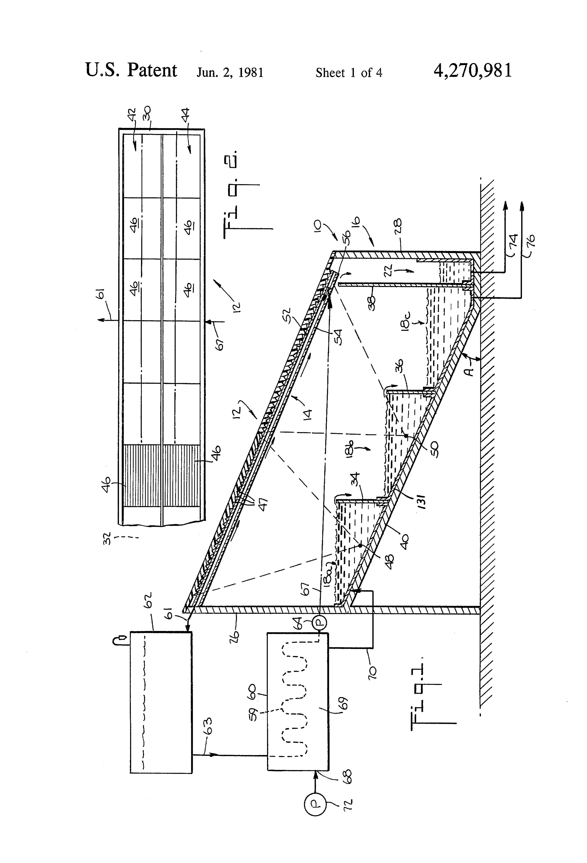
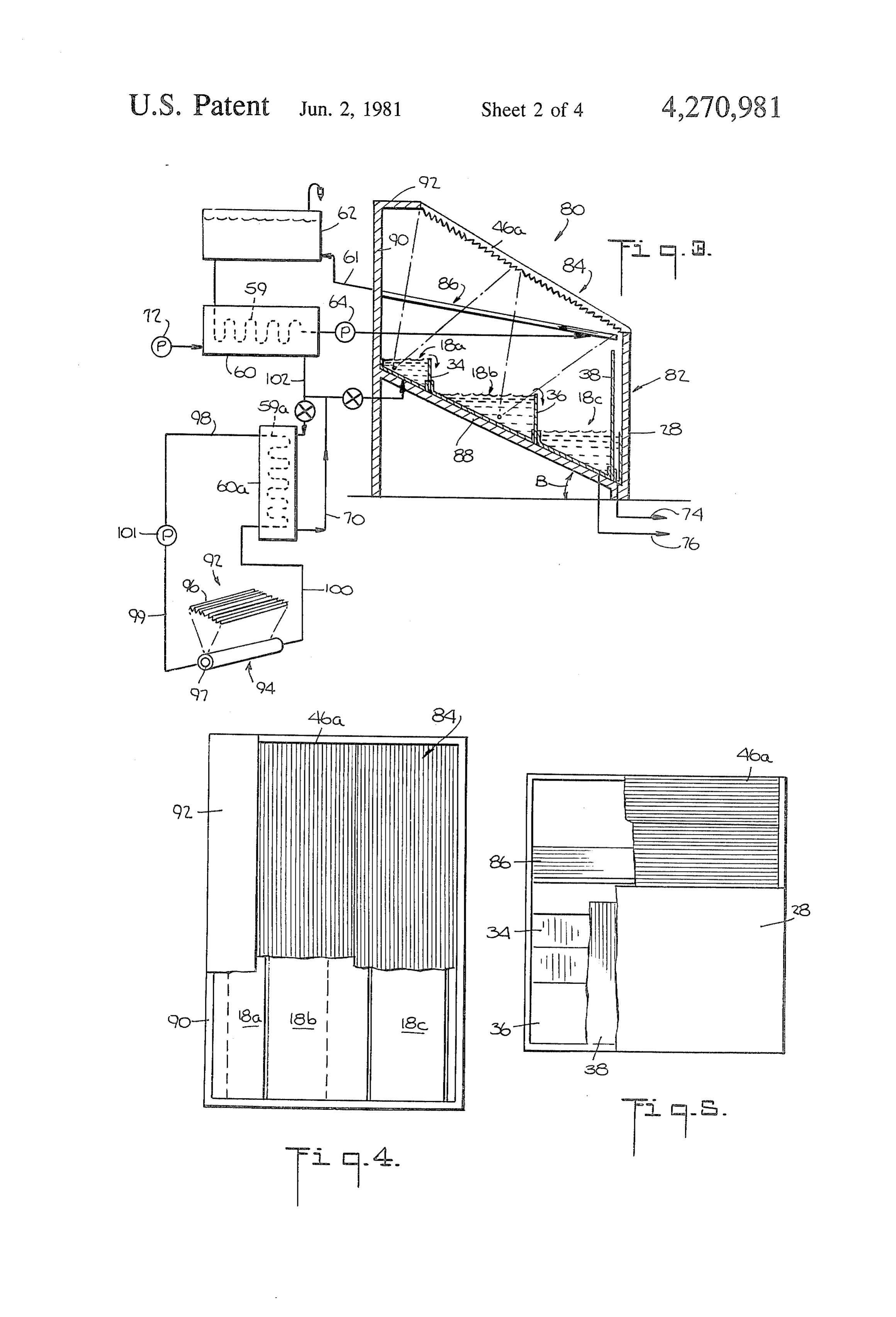
liquid concentrated with impurities (brine) may be re 45 FIG. 1 is a vertical cross-section schematic view of covered and the concentration of thereof may be in solar distillation apparatus according to the invention creased in successive compartments and units, allowing showing two adjacent sets of Fresnel lenses arranged a more economical extraction of, for example, salts from above a container holding water to be distilled, a trans the brine. parent plate-like conduit on which vapor is condensed A separate heat exchanger using a fluid heated, for 50 being interposed between the container and the lenses, instance, to 150° C. by solar energy in a separate solar the plate-like conduit and the lenses being inclined at energy unit can be used to preheat the liquid to be dis about the same angle to be substantially parallel; tilled, increasing its temperature, in the case of water to, FIG. 2 is a top plan schematic view, partly broken for instance, 75 C., before introducing the liquid into away, of the solar distillation apparatus of FIG. 1; the distillation compartment. 55 FIG. 3 is a vertical cross-section schematic view of In accordance with another embodiment of the in solar distillation apparatus according to the invention vention, the sets of Fresnel lenses are arranged so that similar to that shown in FIG. 1 with the Fresnel lenses the elongated focus of at least one set is substantially being inclined at a greater angle than the plate-like parallel to the axes of the compartments in the container conduit; - and the elongated focus of at least one other set is ar 60 FIG. 4 is a top plan view, partly broken-away, of the ranged so that the elongated focus is transverse to the solar distillation apparatus of FIG. 3; axes of the compartments. According to this embodi FIG. 5 is an end elevation schematic view, partly ment, the focus which is transverse to the axis of the broken-away, of the solar distillation apparatus of FIG. compartments extends into varying depths of liquid in 3;
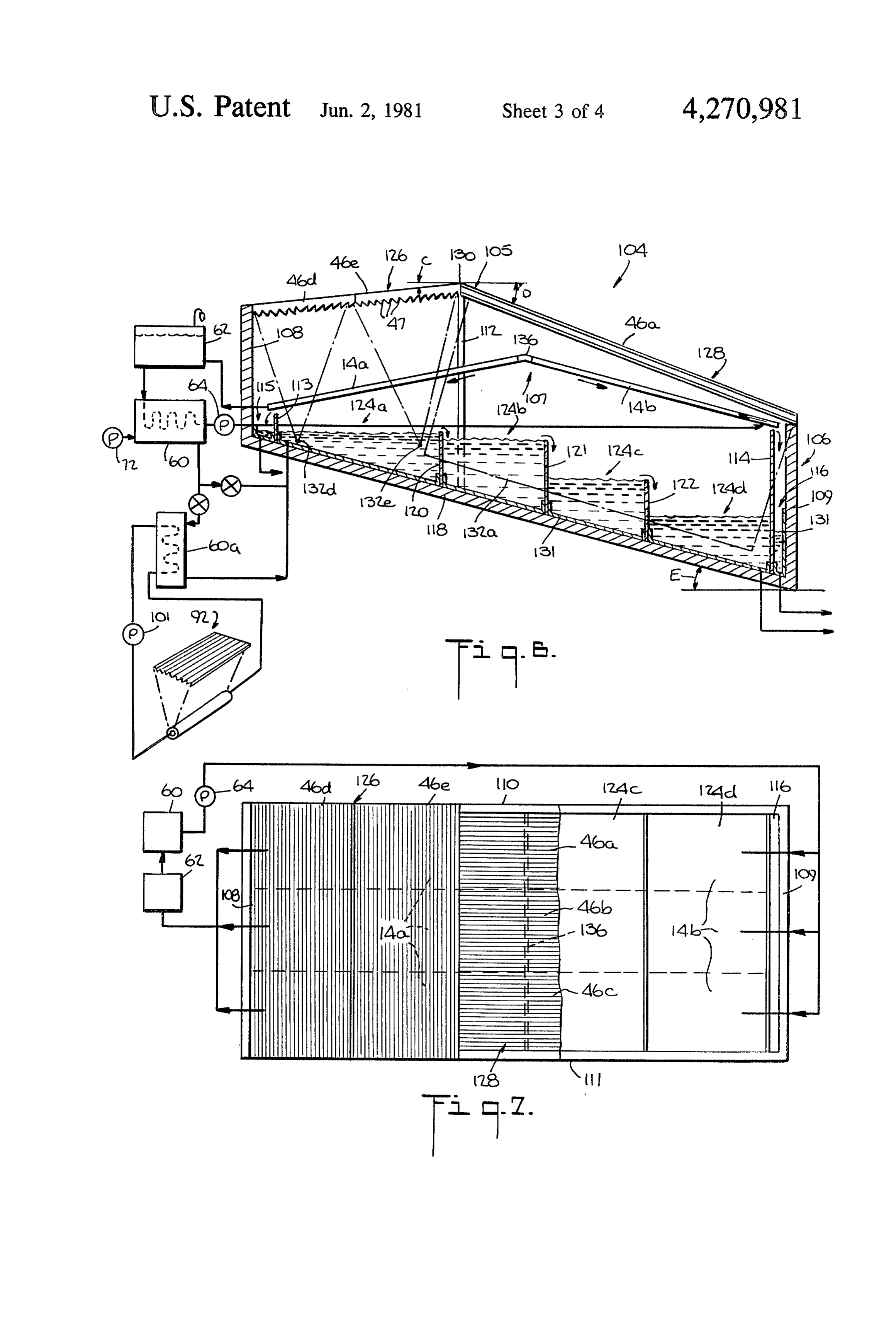
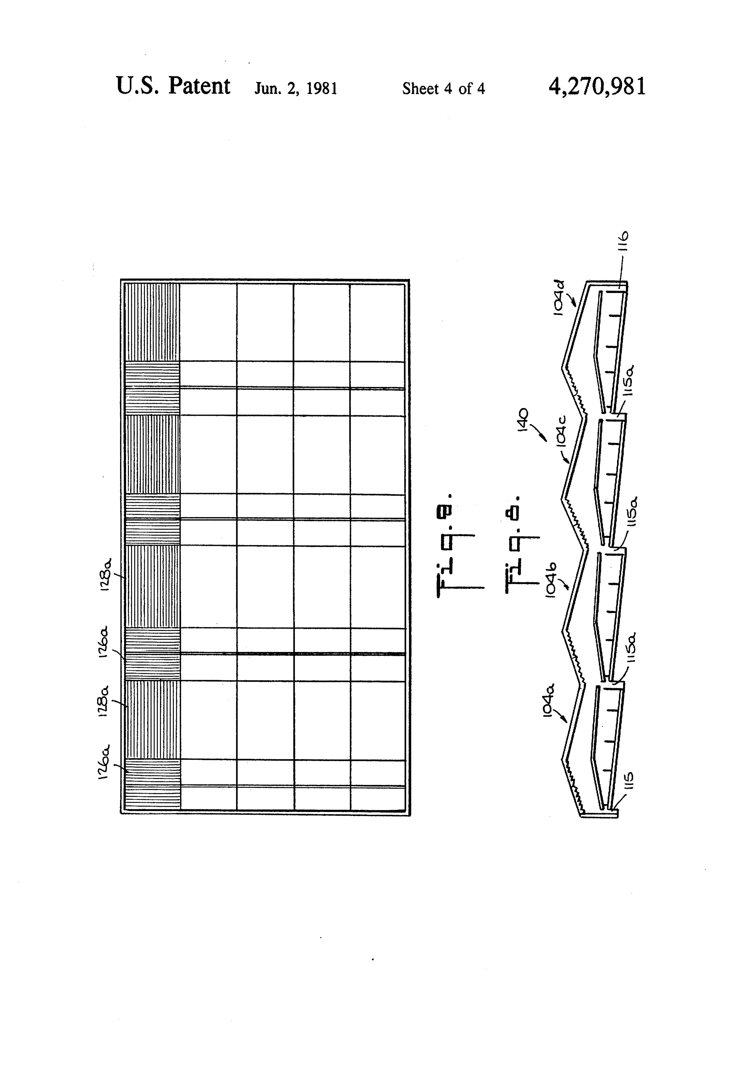
the container. The two sets of Fresnel lenses are ar 65 FIG. 6 is a vertical cross-section schematic view of ranged at an angle to each other so that they meet along solar distillation apparatus according to still another an apex with each set having a lower end. The conduit embodiment of the invention showing two sets of Fres system on which vapor condenses is made up of two flat nel lenses arranged above the container for the water to 8 be distilled with an inclined transparent plate-like con six lenses; however, one or three or more series of lenses duit on which vapor is condensed interposed between and more or less than six lenses may be utilized per the lenses and the container, one set of lenses extending series depending upon the size of the installation and the generally parallel to the axis of container and one set of quantity of distilled water desired. Each Fresnel lens lenses extending transverse to the container axis, the 5 comprises longitudinally extending prisms 47 which two sets of lenses being adjacent and inclined with re provide an elongated narrow focus. The series of lenses spect to each other and with respect to the container are arranged to provide spaced parallel elongated com and plate-like conduit; posite foci 48, 50. The composite focus 48 of lens series FIG. 7 is a top plan schematic view of the solar distil 42 is located in the water in compartment 18a while the lation apparatus of FIG. 5; - O composite focus 50 of lens series 44 is located in the FIG. 8 is a vertical cross-section schematic view of a water in compartment 18b, each focus extending sub composite solar distillation apparatus utilizing a plural stantially parallel to the elongated axis of the respective ity of systems of the type shown in FIGS. 6-7; and compartment. Offsetting the height of the compart FIG. 9 is a top plan schematic view of the composite ments, i.e. providing an inclined lower surface of the system of FIG.8. 15 container and spaced baffles, permits the foci of the DESCRIPTION OF THE PREFERRED inclined lens system to be located in the different com
Interposed between the lens system 12 and the top of
Referring more particularly to the drawings, appara the container is the transparent flat plate conduit 14. tus for the solar distillation of water are illustrated. In 20 Conduit 14 is inclined downwardly from side 26 sub FIG. 1, the distillation apparatus 10 includes a Fresnel stantially parallel to the inclination of the lens system, lens system 12 to concentrate the solar energy, a trans i.e. at approximately angle A, and includes spaced op parent flat plate conduit 14 on the bottom of which posed transparent plates 52, 54 which extend down water vapor is condensed, and a container 16 having wardly from side 26 to above the compartment 22 for compartments 18a,b,c for the water to be distilled and a 25 the distilled water. The flat plate conduit i4 is substan compartment 22 for distilled water which is discharged tially co-extensive with the lens system and extends from the bottom of the conduit 14. The sides 26, 28 of between ends 30 and 32 and from side 26 downwardly, the container are offset in height and the lens system 12 terminating short of side 28 of the container. The flat extends inclined along the sides of the container be plate conduit and the Fresnel lenses are disposed to tween the ends 30, 32 thereof, the lens system closing 30 have a minimal air space therebetween to reduce trans the top of the container and being supported by the mission losses through the lenses and conduits and to sides and ends of the container. Compartment 18a in the reduce heat losses. In the embodiment shown in FIGS. container is formed by the side 26 of the container, a 1 and 2, angle A has a maximum value of about 20. baffle 34 and the ends of the container; compartment the transparent plates 52, 54 are made for example of 18b by baffles 34 and 36 and the ends of the container, 35 glass or plastic and are sealed along the peripheries and compartment 18c by baffle 36, partition 38 and the thereof to be fluid-tight and thusly form the conduit 14. ends of the container. The partition 38 separates the The plates may be sealed at their peripheries by, for compartments 18a,b,c holding water to be distilled from example, welding or with a sealant such as silicone. A compartment 22 holding the distilled water. Compart frame may be provided in which the edges of the plates ments 18a,b,c extend parallel to the elongated axis of the 40 are mounted fluid-tight using, for example, a silicone sealant. The plates 52, 54 are planar or flat, as men
The bottom 40 of the container is inclined down tioned, and are parallel, being spaced by a distance of wardly from side 26 to side 28 at an angle A with re from about 6 mm to about 12 mm. Openings are pro spect to the horizontal. The heights of baffles 34 and 36 vided to the interior of conduit i4 to permit the evacua are substantially equal to provide the inclined container 45 tion of air therefrom and for the circulation of a fluid bottom 40 with stepped compartments 18a,b,c so that through the conduit 4. The lower plate 54 forms a during normal distillation operation, the maximum vapor barrier over the container, depths of the water to be distilled in compartments The plates forming the conduit 14 may alternatively 18a,b,c are substantilly equal. The water to be distilled is be co-extensive in lenght and width with each Fresnel introduced into compartment 18a and overflows there 50 lens series or each lens, with the plates being adjacently from into the othe compartments. The height of parti disposed and sealed and the lower surfaces of adjacently tion 38 is higher than the heights of baffles 34, 36 so that sealed plates forming a vapor barrier over compart the water to be distilled does not flow into compartment ments 8a,b,c to prevent escape of vapor therepast. A 22. Since compartment 18a is separated from the other frame and/or a sealant may be used to sealingly join compartments, the introduction therein of the water to 55 adjacent plates.
be distilled does not directly cool the heated water in The lower end 56 of the conduit is supported by the other compartments. frame means and is spaced from the top of partition 38 The lens system 12 is inclined downwardly, extend to provide the only opening through which vapor may ing from the higher side 26 to the lower side 28 of the pass from the compartments. However, the spacing is container substantially parallel to the container bottom 60 small and the escape of vapor therethrough is negligl 40 at approximately the angle A with the horizontal. ble. Water vapor evaporated from compartments The lens system 12 includes two series 42, 44 of adja 18a,b,c rises and impinges upon the bottom of the con cently disposed Fresnel lenses 46, each series extending duit 14 and condenses thereon. The condensate flows substantially parallel to the elongated axes of the con downwardly past the opening between the partition 38 tainer and compartments 18a,b,c. The inclined, parallel 65 and the conduit towards end 56 of the conduit and is lenses are spaced by, for example, one inch to prevent discharged therefrom into compartment 22 for the dis ing shadowing of adjacent lenses. Two series of lenses tilled water. Thus, the opening between the partition 38 are shown and each series of lenses is shown to include and the bottom surface of the conduit need only be 9 large enough to permit the condensate to flow there water vapor rises and impinges upon the bottom plates past. of the conduit and is condensed thereon. The conden As mentioned, the plates are mounted fluid-tightly to sate flows donwardly along the bottom plates and is form conduit 14 with the lower surface of the conduit discharged into compartment 22. Distilled water is re forming a vapor barrier. The plates are thus mounted to 5 moved from compartment 22 through conduit 74. The form a fluid-tight, elongated, generally rectangular en water in compartment 18c is a concentrated brine also closure through which a heat exchange fluid may be containing other minerals such as magnesium chloride circulated. As mentioned, water vapor impinges upon and magnesium sulfate and is removed through conduit the bottom of the conduit and is condensed thereupon. 76.
Upon condensation of the water vapor, the heat of 10 A clear heat exchange fluid is circulated through the condensation thereof is released and heats the bottom flat plate conduit, as mentioned, to recover a substantial plate or plates of the conduit. The bottom plate or plates part of the heat of condensation of the condensing liquid are also heated by the sensible heat of the vapor and and to cool the bottom plates of the flat plate conduit to condensate. A heat exchange fluid is circulated through enhcance condensation. The heat exchange fluid is cir the conduit to recover a substantial part of the heat of 15 culated through the heat exchanger and the heat re condensation and the sensible heat and to cool the bot moved from the heat exchange fluid is transferred to the tom plate(s) of the conduit to enhance condensation incoming water to be distilled to preheat it. Thus, a thereon. , substantial portion of the heat of condensation is recov The interior of the conduit 14 is connected to the coil ered and used to increase the efficiency of the system. 59 of a heat exchanger 60 by conduits so that the heat 20 The heat exchange fluid circulated in the conduit exchange fluid may be circulated through the conduit may be Therminol 66, a clear liquid available from 14 and the heat exchanger 60. An expansion tank 62 for Monsanto, or a similar liquid, or distilled water which the heat exchange fluid is provided between the conduit may have a product such as glycol added thereto to 14 and the coil of the heat exchanger, conduit 61 con raise the boiling point of the distilled water and lower necting conduit 14 to the reservoir. The expansion tank 25 its freezing point.
is located at approximately the same height as the con According to the invention, the flat plate conduit is duit 14 to minimize pressure in the conduit. Preferably, used to condense the water vapor and accordingly the the heat exchanger is located within about 50 cm verti plates thereof are spaced and the heat exchange fluid cally from the expansion tank to provide a small height therein is chosen to permit maximum transmission of difference in the levels of the heat exchange fluid, 30 Solar energy therethrough while accomplishing con thereby requiring a low pressure to circulate the fluid. densation of the water vapor and recovery of a substan Angle A may be changed to further reduce the pressure tial part of the heat of condensation. The fluid circulat required to circulate the fluid. Thus, the conduit need ing in conduit 14 is also heated by the absorption of not withstand high pressures. The heat exchange fluid solar energy transmitted through the Fresnel lenses and may be circulated by pump 64 about a closed circuit 35 from solar energy reflected to the fluid in the conduit which passes through the conduit 14, conduit 61, the from the water in the container.
expansion tank, conduit 63 the coil 59 of the heat ex In the embodiment shown in FIGS. 1 and 2, the Fres changer and conduit 67. Water to be distilled is intro nel lenses 46 can, for example, be about 84 cm wide by duced through inlet 68 into a chamber 69 in the interior about 250 cm long and have a concentration factor of of the heat exchanger so that the water in the chamber 40 about 40 and a focal width of about 2 cm; the container and the fluid in the coil are in a heat exchanging rela can, for example, be about 168 cm wide by about 125 cm tionship. The chamber is connected to compartment long and the height of baffles 34 and 36 can, for exam 18a by conduit 70. Thus, the water to be distilled may ple, be about 50 cm. The width of the compartments be pumped by pump 72 through the heat exchanger and can, for example, be about 40 cm. The water depth in discharged into compartment 18a of the container. Con 45 the compartments can correspondingly be about 5 cm duits 61 and 67 have been shown to include only one to about 50 cm, which is relatively shallow. The appara conduit each. However, it is understood that each may tus 10 is arranged with its longitudinal axis in the east comprise more than one conduit depending upon the west direction and the lens system facing South. Prefer size of conduit 14 and the quantity of fluid circulated ably, the bottoms of the compartments are blackened by therethrough. 50 a flexible dark sheet 131 such as Esso Butyl or a similar In operation, solar energy is concentrated by lens material which is also water tight and is capable of series 42, 44 in elongated foci 48, 50 located in the water withstanding temperatures of up to 100 C. and will in compartments 18a, 18b respectively. Water is intro absorb heat and transfer it to the water to be distilled to duced into the container in compartment 18a and upon increase the temperature thereof. This will allow use of overflowing baffle 34, enters compartment 18b, upon 55 levelled earth instead of concrete for the bottom of the overflowing baffle 36, the water enters compartment channel, thereby reducing the cost of the installation. 18c. As the water moves from compartment 18a to The temperature of the water introduced into compart compartment 18c, it is progressively heated in compart ment 18a is about 55 C. and can gradually reach about ments 18a and 18b by the concentrated solar energy and 85 C. therein.
a substantial portion thereof is evaporated. Since the 60 The quantity of fluid circulated in the flat panel con water overflowing into compartment 18b has been duit 14 is much larger, for instance, by 10 times, than the heated in compartment 18a by the solar energy concen quantity of distilled water obtained through evapora trated along focus 50, the water in compartment 18b tion and condensation of vapor on the conduit. This will reach a higher temperature than the water in com large quantity of fluid is required to carry off the recu partment 18a so that evaporation from compartment 65 perated heat of condensation while maintaining the 18b in the central part of the container is accelerated. temperature of the fluid below that of the condensing Heater water overflows into compartment 18C from vapor. Thus, condensation of the water vapor continues compartment 18b with evaporation continuing. The on the bottom plate of conduit 14.
Page 10scan →
Referring now to FIGS. 3-5, the solar distillation portions of the container ends, compartments 124a,b,c,d apparatus 80 includes a container 82, a Fresnel lens for the water to be distilled. The heights of the baffles system 84 and a transparent flat plate conduit 86 similar 120-122 are less than the heights of the partitions 113, to that shown in FIGS. 1 and 2 and described above. 114 so that the water to be distilled will not overflow The container bottom 88 and the Fresnel lens system 84 into compartments 115, 116 during normal distillation are each approximately inclined at an angle B with the operation.
horizontal while the transparent flat panel conduit is The lens system 105 includes lens series 126 and 128 inclined at the angle A, as in FIGS. 1 and 2. Angle B is of Fresnel lenses 46. The lenses of series 126 are ar in the range of from about 25 to about 60°. The higher ranged with their longitudinal axes and the axes of the side 90 of the container includes a shoulder 92 to sup O refracting prisms 47 extending parallel to the longitudi port the Fresnel lens system and space it from side 90so nal axes of the compartments. The lenses of series 128 that the focus of lens 46a is located in compartment 18a, are arranged with their longitudinal axes and with the as in FIGS. 1-2. The transparent flat plate conduit is axes of the refracting prisms 47 of the lenses extending spaced from the lens system since the lens system and substantially transversely to the longitudinal axes of the flat plate conduit are inclined at different angles with 15 compartments. Lens series 126 and 128 are inclined with the horizontal, the lens system and flat plate conduit respect to each other with the two lens series meeting being inclined with respect to each other at an angle of over the container and forming an apex 130 thereabove. B-A. The lens system and conduit are therefore sepa Lens series 126 extends from apex 130 downwardly at rated. The baffles 34 and 36 are of unequal height, baffle an angle C with the horizontal and is supported by side 36 being higher than baffle 34 to provide a greater depth 20 108 of the container. Lens series 128 extends from apex of water in compartment 18b. 130 downwardly at an angle D with the horizontal and Apparatus 80 also includes a separate solar heater 92 is supported on side 109 of the container. Support 112 which is illustrated to be of the type disclosed in U.S. extending at the apex supports the lens system thereat. Pat. No. 4,134,393 which is hereby incorporated by Side 108 is higher than side 109 and the apex 130 is reference. The collector 94 of heater 93 includes two 25 located closer to side 108 than side 109. Therefore, conduits carrying fluids therein heated by solar energy angle D is greater than angle C. The bottom 118 of the concentrated by lens system 96. The coil 59a of heat container is inclined at an angle E with the horizontal, exchanger 60a is connected to one of the conduits, pref the water to be distilled being introduced into compart erably the outer conduit 97 and a heat exchange fluid is ment 124a and overflowing into compartments 124b-d. circulated through the outer conduit and coil 59a. Con 30 Concentrated brine is removed from compartment duits 98-100 complete the circuit with the fluid being 124d.
pumped by pump 101. Conduit 102 connects the cham Each of lenses 46a,b,c of lens series 128 has an elon bers of the two heat exchangers, and conduit 70 con gated focus 132a,b,c extending transverse to the axes of nects the chamber of exchanger 60a to compartment the compartments (FIG. 6) and extending through 18a. Heater 92 is used to assist in preheating the water to 35 varying depths of water. Each of lenses 46de has an be distilled which is introduced into compartment 18a elongated focus 132de extending within compartment of apparatus 80. The water to be distilled passes first 124a with the axes of foci 132d,e extending substantially through heat exchanger 60 as described for FIG. 1, and parallel to the axis of compartment 124a, each focus then through heat exchanger 60a before being intro extending through a substantially constant water depth duced into compartment 18a through conduit 70. 40 with the two foci being at different water depths. Apparatus 80 operates similar to apparatus 10 and The transparent conduit system 107 includes trans provides additional heat from heater 92 to preheat the parent conduits 14a, 14b inclined with respect to each water introduced into container 82. Additionally, the other along apex 136, each extending downwardly at lens system is inclined at an optimum angle towards the the angle A, as described for FIGS. 1-5, towards sides South to collect additional solar energy. A fluid as de 45 108 and 109, respectively. Supports suspend the trans scribed for conduit 14 of FIG. 1 is circulated through parent conduits above the container with the lowermost heater 92 and can be heated to about 280 C. The heat ends of the conduits being above compartments 115, exchanger 60 transfers heat recovered by the fluid in 116. Each conduit lower surface forms a vapor barrier conduit 14 to the water to be distilled. In apparatus 80, as described for conduit 14 in FIGS. 1-5 and the lower the water is preheated and introduced into compart 50 surface of the apex is sealed fluid-tight so that the con ment 18a at a temperature which can reach about 75 C. duit system 107 forms a vapor barrier above the con Other details of apparatus 80 are similar to apparatus tainer. The circuit for the fluid in the conduits 14a and 10. Only two Fresnel lenses have been shown for appa 14b passes serially through the conduits and the heat ratus 80 for clarity, but it is understood that the lens exchanger 60. The water to be distilled passes serially System may comprise series of lenses as for apparatus 55 through heat exchanger 60 and heat exchanger 60a. The angles of inclination of the lens series exceeds angle A
In FIGS. 6-7, solar distillation apparatus 104 includes and there is a space between the conduit system and the a lens system 105, container 106 and a flat-plate trans lens system, as described for FIGS. 3-5. parent conduit system 107. Container 106 includes sides Apparatus 104 also includes the heat exchanger 60a 108, 109 and ends 110, 111 which with support 112 and the solar heater 92, as described for FIGS. 3-5. support the lens system 105. The container 106 com Moreover, two conduits 14a, 14b are provided and two prises partitions 113, 114 disposed in the container adja compartments for the distilled water are provided to cent walls 108, 109 to form compartments 115, 116 for increase the production of distilled water. the distilled water. Each compartment is formed by the Apparatus 104 is arranged so that the compartments bottom 118, sides and portions of the ends of the con 65 extend generally east-west and operates similar to appa tainers and the partitions. Baffles 120-122 are also pro ratus 10 and 80. Apparatus 104 includes the intersecting vided in container 106 extending substantially parallel lens foci which serve to heat the water at different to the partitions to form with partitions 113 and 114 and depths transverse to the axis of the compartments as 11 well as substantially parallel to the axes of the compart elongated conduit means disposed between said lens ments. Additionally, the lens system 105 includes lens means and said containing means for condensing series which can be tilted to the north and to the south evaporated liquid thereon, said conduit means at, for example, 10' and 30', respectively to collect being transparent at least in part so as to allow solar more solar energy than the apparatus of FIGS. 1-5. The energy concentrated by said lens means to pass temperature of the water in compartments 124-a-d can therethrough and reach said containing means, said gradually reach about 85 C. conduit means including means for admitting fluid While the lens series 126, 128 have been shown to to and withdrawing fluid from said conduit means include three and two Fresnel lenses, respectively, it is such that a fluid can be passed through said conduit understood that each series may comprise more or less 10 means, said conduit means including a substantially lenses having the same or different sizes so that the lens smooth surface disposed above the containing system extends over substantially the entire top of the means and positioned such that rising liquid vapor container. impinges upon said surface and is condensed Although not shown, means may be provided to thereon, said smooth surface being operative to move the lens systems to track the sun to further in 15 transmit at least in part the heat of condensation crease production of distilled water. released by evaporated liquid condensing thereon Mirrors may be disposed along selected portions of to the interior of said conduit means where such the prisms of the Fresnel lenses to further concentrate heat may be absorbed by the fluid in said conduit the solar energy in the liquid to be distilled. means and thereby may be recovered, said smooth Excess water vapor not condensed in the distillation 20 surface having a vertically lower portion such that apparatus may be removed and superheated in a heat condensed liquid flows along said surface to said exchanger using a heater such as solar heater 92. The vertically lower portion thereof and is discharged superheated steam at 250° C. for example, can be ex therefrom, and panded in a turbine to obtain power and condensed to 25 liquid collecting means disposed below said lower obtain additional distilled water. portion of said smooth surface for collecting con Referring now to FIGS. 8 and 9, a composite distilla densed liquid discharged from said lower portion. tion system 140 is shown which comprises a plurality of 2. The apparatus as recited in claim 1, wherein said individual, adjacently arranged systems 104a-104d. conduit means comprises a planar lower wall which Each system 104a-104d is similar to system 104 with 30 forms said smooth surface.
adjacent systems having common compartments 115a 3. The apparatus as recited in claim 2, wherein said for receiving distilled water. Each system 104a-104d is said conduit means comprises an upper wall spaced from lower wall.
individually supplied with water to be distilled and heat exchange fluid for circulating in the conduit system of upperThe 4.
wall apparatus as recited in claim 3, wherein said is planar.
each system 104a-104d. Common conduits, however, 35 5. The apparatus as recited in claim 4, wherein said may be used to supply and withdraw the water and upper and lower walls are parallel. fluid.
The brine which is a high temperature and at a higher said6. The apparatus as recited in claims 3 or 5 wherein concentration than the water (salt water) to be distilled, part, upper and lower walls are transparent at least in can be serially fed to one or more successive distillation conduit meansmeans said lens and the transparent portions of the units. Moreover, a countercurrent arrangement may be centrated by said lensdisposed being means so that solar energy con passes through the trans set up within a single unit or among several units in parent portions into the liquid to be distilled. which the concentrated brine of downstream compart 7. The apparatus as recited in claim 6, wherein said ments is supplied to the upstream compartments. Thus, upper and lower walls are parallel upper and lower the heat in the brine at about 80 C., for instance, can be 45 transparent recuperated and used to enhance evaporation of water conduit, saidflat plates sealingly joined to form a flat smooth outer surface being the outer sur in other compartments or units. Additionally, the brine face of said lower plate.
will be concentrated and allow a more economic extrac tion of salt and/or other chemicals such as magnesium lens8. The means apparatus as recited in claim 7, wherein said comprises at least one Fresnel-type lens chloride, magnesium sulfate, etc., therefrom. 50 which concentrates the solar energy through said plates The advantages of the present invention, as well as certain changes and modifications of the disclosed em in 9.anThe elongated focus in the liquid to be distilled. apparatus as recited in claim 8, wherein said bodiments thereof, will be readily apparent to those conduit means skilled in the art. It is the applicant's intention to cover cent each othercompriseswith the two conduits disposed adja lower surfaces thereof being by his claims all those changes and modifications which 55 oppositely inclined, and including an elongated con could be made to the embodiments of the invention tainer in which said containing means and said liquid herein chosen for the purposes of the disclosure without collecting means are disposed, said containing means departing from the spirit and scope of the invention. being disposed centrally in the container and a liquid Protection by Letters Patent of this invention in all its collecting means being disposed below each said lower aspects as the same are set forth in the appended claims 60 end separated by said containing means, said lens means is sought to the broadest extent that the prior art allows. comprising at least two adjacently disposed Fresnel What is claimed is type lenses, a first of said Fresnel-type lenses being 1. Apparatus for distilling a liquid such as water using inclined in the direction of one of said conduits and a solar energy comprising: second of said Fresnel-type lenses being inclined in the means for containing the liquid to be distilled; 65 direction of the other of said conduits. lens means disposed above said containing means for 10. The apparatus as recited in claim 9, wherein said concentrating the solar energy in said liquid to be container includes side and end walls and two partitions distilled; therein disposed adjacent opposed side walls thereof, 12 each partition with walls of said container forming a focus located in said lower compartment, said elongated liquid collecting compartment, each of said liquid col container including inlet means for introducing the lecting compartments being disposed below a respec liquid to be distilled into said upper compartment. tive lower end to receive condensed liquid falling there 18. The apparatus as recited in claim 17, wherein said from, and wherein said conduits substantially cover said elongated container includes outlet means for removing container, and wherein said container includes at least liquid to be distilleld concentrated with substances to be two baffles extending said containing means to separate removed therefrom in said lower compartment. said container means into at least three compartments 19. The apparatus as recited in claim 17, and compris for containing liquid to be distilled, an elongated focus ing a plurality of said apparatus adjacently arranged to of the first Fresnel-type lenses being substantially lo 10 form a composite apparatus, adjacent apparatus having cated in one of said compartments for containing liquid common compartments for receiving condensed liquid. to be distilled and the elongated focus of the second 20. The apparatus as recited in claim 19, and compris Fresnel-type lens being located at least in part in an ing means for recycling the liquid concentrated with other of said compartments for containing liquid to be substances in at least one successive apparatus, recycled distilled. 15 liquid being introduced into said successive apparatus to 11. The apparatus as recited in claim 10, wherein the replace at least in part liquid to be distilled, whereby axis of the first and second Fresnel-type lenses are sub part of the heat of the recycled liquid is recuperated and stantially normal to each other, the elongated focus of the liquid is further concentrated with substances. the first Fresnel-lens extending through varying depths 2. The apparatus as recited in claim 16, wherein said of liquid in at least said one and another compartments. 20 conduit means and said Fresnel-type lenses are disposed 12. The apparatus as recited in claim i0, and compris adjacent each other and are substantially parallel to ing a plurality of said apparatus adjacently arranged to each other.
form a composite apparatus, adjacent apparatus having 22. The apparatus as recited in claim 21, wherein said common compartments for receiving condensed liquid. conduit means and said Fresnel-type lenses are inclined 13. The apparatus as recited in claim 12, and compris 25 at an angle of from about 5' to about 20' with the hori ing means for recycling the liquid concentrated with zontal.
substance in at least one successive apparatus, recycled 23. The apparatus as recited in claim 16, wherein said liquid being introduced into said successive apparatus to conduit means and said Fresnel-type lenses are spaced replace at least in part liquid to be distilled, whereby and disposed at an acute angle with each other, said part of the heat of the recycled liquid is recuperated and 30 conduit means being disposed at an angle of from about the liquid is further concentrated with substances. 5 to about 20' with the horizontal and said Fresnel 14. The apparatus as recited in claim 7, and compris type lenses being disposed at an angle of up to 60 with ing a container in which said containing means and said the horizontal.
liquid collecting means are adjacently disposed, said 24. The apparatus as recited in claim 14 and compris container including side and end walls and a partition 35 ing a flexible, dark material which is impermeable to the disposed adjacent one wall of the container, the parti liquid to be distilled disposed on the bottom of said tion and walls of the container forming a compartment containing means and which is operative to absorb solar disposed below said lower portion of said lower plate to energy to produce heat and transfer such heat to the form said liquid collecting means for collecting con water to be distilled.
densed liquid falling therefrom, said lower plate sub 40 25. The apparatus as recited in claim 24, wherein said stantially covering said containing means and forming a material is disposed on suitably worked ground and vapor barrier thereabove. forms the bottom of said containing means. 15. The apparatus as recited in claim 4, wherein said 26. The apparatus as recited in claim 1, and compris container is elongated and said lens means comprise a ing a heat exchange fluid passed through said conduit plurality of elongated Fresnel-type lenses each concen 45 means and heat exchanging means for transferring heat trating the solar energy in an elongated focus in the from the fluid in said conduit means to the liquid to be liquid to be distilled, the elongated axes of said Fresnel distilled.
type lenses and said elongated container being substan 27. The apparatus as recited in claim 26, wherein said tially parallel. heat exchanging means comprises a heat exchanger 16. The apparatus as recited in claim 15, wherein said 50 comprising a first circuit for the liquid to be distilled elongated container includes at least one baffle extend including a first inlet for the introduction of the liquid to ing in said containing means substantially parallel to the be distilled into said circuit and a first outlet connected elongated axis of the container to form at least two to the interior of said containing means; and a second compartments in said containing means, and wherein circuit for the heat exchange fluid including a second the bottom surface of said containing means is inclined 55 inlet and a second outlet connected to the interior of in the same direction as the Fresnel-type lenses and the said conduit means.
conduit means. 28. The apparatus as recited in claim 1, and compris 17. The apparatus as recited in claim 16, wherein said ing a solar energy heating means for preheating the elongated container includes a plurality of spaced baf liquid to be distilled before the liquid is introduced into fles extending said containing means substantially paral 60 said containing means.
lel to the elongated axis of said elongated container 29. The apparatus as recited in claim 1 wherein the dividing said containing means into at least three adja lens means comprises at least one fluid lens. cent compartments which are offset in height, and 30. Apparatus as recited in claim 1 and including a which define an upper compartment, an intermediate heat exchange fluid passed through said conduit means compartment and a lower compartment, said plurality 65 and means for passing a quantity of fluid through said of Fresnel-type lenses being disposed to concentrate conduit means which exceeds substantially the quantity Solar energy in a first elongated focus located in said of liquid evaporated and condensed on said conduit intermediate compartment and in a second elongated means as to enable the fluid in the conduit means to 13 carry the heat of condensation released by the condens means being disposed in an upper of said compartments ing liquid while maintaining the temperature of the fluid for introducing liquid to be distilled therein and outlet lower than the temperature of the liquid vapor. means being disposed in a lower of said compartments 31. The apparatus as recited in claim 1, wherein said for removing a concentrate of the liquid being distilled, containing means comprises a container including side and end walls and a bottom surface inclined with re whereby liquid to be distilled can be introduced into the spect to the horizontal, at least one baffle being disposed upper compartment, conducted to the lower compart in said container to provide at least two compartments ment and removed from the lower compartment. in said container for holding liquid to be distilled, inlet : k k :
Page 14scan →
United states patent and trademark office
Certificate of correction
PATENT NO. : 4, 270,98l Page 1 of 2
It is certified that error appears in the above-identified patent and that said Letters Patent is hereby corrected as shown below:
Column 4, line 16, change "asepect" to --aspect--; line 33, change "pretroleum" to
Column 5, line 49, change "substantilly" tO line 5l, change "othe" to -- other--;
lines 66-67, change "preventing" to line 49, change "lenght" to --length -- ; lines 60-61, change "negliglible" to
Page 15scan →
United states patent and trademark office
Certificate of correction
PATENT NO. : 4, 270,981 Page 2 of 2
NVENTOR(S) Virgil Stark it is certified that error appears in the above-identified patent and that said Letters Patent is hereby COrrected as shown below:
Column 7, line 67, change "Heater" to --Heated.--.
Column 8, line 3, change "donwardly" to --downwardly--;
line l4, change "enhcance" to --enhance--.
Column ll, line 38, change "a" (first occurrence) to line 62, after "is" insert -- :--.
Column 13 line 27, change "substance" to -- substances--;
Column l4, line 6, change "distilleld" to --distilled--.
eigned and Sealed this
O Tenth D ay of November 1981
Seal
Attest:
O GERALD J. MOSSINGHOFF Attesting Officer Commissioner of Patents and Trademarks
Provenance
- Collection
- Patents citing this work
- Pages
- 15
- Method
- pdftotext (the PDF's own text layer) + pdftoppm 300dpi page scans
- Patent office record
- patents.google.com →
- Source
- Google Patents citing-documents table
- Assignee
- North American Utility Construction Corp.
- Published
- 1981-06-02
- Transcribed from
- patentimages.storage.googleapis.com →