

patent · US4487659A
Solar distillation apparatus
11 December 1984
Text
Page 1bibliographic recordscan →
United States Patent (19)
Stark
54). SOLAR DISTILLATION APPARATUS
Inventor: Virgil Stark, New York, N.Y.
Assignee: North American Utility Construction Corp., New York, N.Y.
*) Notice: The portion of the term of this patent subsequent to Jun. 2, 1998 has been disclaimed.
Related U.S. Application Data
Pat. No. 4,323,052, which is a continuation-in-part of
continuation-in-part of Ser. No. 915,001, Jun. 13, 1978,
Int. Cl. ................................................ CO2F 1/14 (52) U.S. Cl. .................................... 202/172; 202/173;
4,312,709 l/1982 Stark et al. . ... 203/DEG. 4,323,052 4/1982 Stark ............................. 203/DIG.
OTHER PUBLICATIONS
B. E. Swaidan & Eugene E. Cooper "Highly Efficient Solar Still' Navy Tech. Disclosure Bulletin, vol. 4, No.
Primary Examiner-Wilbur Bascomb
Attorney, Agent, or Firm-Kenyon & Kenyon
Solar distillation apparatus is disclosed in which the released heat of condensation of the condensing liquid is recovered in a transparent conduit disposed over the liquid to be distilled. Solar energy passes through the transparent conduit and is received on an undulated plate system over which the liquid to be distilled is conducted. A cooling fluid is circulated through the conduit to absorb heat released by the condensing liq uid. In one embodiment, the conduit does not concen trate the solar energy. The conduit is preferably dis posed at an angle of up to about 25' with the horizontal so that the system is subjected to minimal pressure. In another embodiment the conduit defines a fluid lens system which concentrates the solar energy on the plate system. Provision is also made to recover heat from the condensate and a concentrate of the liquid to be dis tilled.
40 Claims, 5 Drawing Figures
Drawings
Page 2drawing sheetscan →
Page 3drawing sheetscan →
Page 4drawing sheetscan →
Page 5scan →
be distilled and is inclined so that the compartments are
SOLAR DISTILLATION APPARATUS offset in height. The bottom of the compartments con taining the liquid to be distilled may be blackened to
RELATED APPLICATIONS allow absorption of solar energy and enhance the heat This application is a continuation-in-part of my co ing of the liquid. The elongated foci of the lenses may be pending application Ser. No. 44,901 filed June 4, 1979 located in and along a different compartment or they (now U.S. Pat. No. 4,323,052), which is a continuation may extend transversely to the compartments. in-part of Ser. No. 1,175 filed Jan. 5, 1979, now aban As disclosed in Ser. No. 915,001, now U.S. Pat. No. doned, which is a continuation-in-part of my copending 10 4,270,981, an expansion tank for the heat exchange fluid applications Ser. Nos. 915,001, filed June 13, 1978 (now in the double plate conduit is located so as to provide U.S. Pat. No. 4,270,981) and 920,288, filed June 29, 1978 minimal pressure within the double plate conduit. A (now U.S. Pat. No. 4,289,118), the disclosures all of heat exchanger is also provided to transfer the heat which are hereby incorporated by reference. recovered in the heat exchange fluid circulated in the
Background of the invention
double plate conduit to the liquid being introduced into 15 the container to preheat the liquid. The heat exchanger
This invention relates to solar energy systems in gen is also located to minimize pressure in the double plate eral and more particularly to solar energy distillation conduit.
systems. As disclosed in Ser. No. 44,901, now U.S. Pat. No. In U.S. Pat. No. 4,134,393, issued on Jan. 6, 1979, of 20 4,323,052, an undulated plate system is provided over which I am a co-inventor, in U.S. Pat. No. 4, 194,949 which the liquid to be distilled is conducted. A single issued on Mar. 25, 1980, of which I am sole inventor, in panel or plurality of adjacent panels made of blackened U.S. Pat. No. 4,210,121 issued on July 1, 1980, of which flexible plastic or the like, such as isobutyl, may be I am sole inventor, and in pending Application Ser. No. disposed over all or part of the plate system. The panel 807,513 filed June 20, 1977, now abandoned, of which I or panels are attached in the plate system in a removable am sole inventor, Solar energy distillation apparatus are manner which will permit removal thereof in order that disclosed in which a part of the heat of condensation of deposits which may form on the panel(s) can be re the condensing liquid is recovered. In the disclosed moved. .
embodiments in those patents and in that application, According to Ser. No. 44,901, now U.S. Pat. No. the heat of condensation is transferred to a fluid in a 4,323,052, it is preferred that the undulated plate system fluid lens disposed over the liquid to be distilled which be placed above includes an inclined bottom surface on which the evap tion obtained from the focal area of maximum concentra orated liquid is condensed and along which the con This permits a wider Fresnel-type lens concentrators. densed liquid flows to be discharged from the lower end from the lenses on thespread of the energy converging undulated plate system so that a thereof. The '949 and 121 patents and the '513 applica wider area of the plate system is heated. A double plate tion also disclose recovering heat from the condensate 35 conduit and from a concentrate (brine) of the liquid being con lens. The fluid circulating in thethedouble is interposed between plate system and the plate conduit is densed.
allowed to spread along the surface of
It is generally undesirable to incline a fluid lens at prising the double plate conduit and is regulated, the plates com more than an angle of about 25 in order to maintain the controlling thus fluid pressure in the lens at a level which does not re the temperature of the fluid. quire a high pressure lens construction. However, at According to Ser. No. 44,901, now U.S. Pat. No. locations where a lens inclination of greater than 25 is 4,323,052, photovoltaic cells can be installed in one or desirable to increase collection, a fluid lens inclined more bottoms or valleys of the undulated plate system only at 25 operates at reduced efficiency. at the locations where the energy is concentrated by the In application Ser. No. 915,001, filed June 13, 1978, 45 Fresnel-type lenses. The photovoltaic cells can be en now U.S. Pat. No. 4,270,981, solar distillation apparatus capsulated in a transparent plastic or glass cover so as to is disclosed comprising conduit means interposed be protect the cells from the liquid being distilled. The tween lens means for concentrating the solar energy cells can also be enclosed in a transparent tube in which and the liquid to be distilled. Solar energy is concen distilled liquid such as cooled condensate produced by a trated by lens means in the liquid to be distilled through 50 distillation unit can circulate and further absorb heat the conduit means. In one embodiment, the conduit generated by the infrared rays. Such a heat exchange means comprise a double plate conduit having an upper can reduce the temperature of the condensate. and a lower plate between which a heat exchange fluid Infrared rays can be absorbed by the fluid in the flows. The concentrated solar energy causes the liquid double plate conduit means (Ser. Nos. 915,001, now to evaporate with the vapor impinging and being con 55 U.S. Pat. No. 4,270,981 and 44.90, now U.S. Pat. No. densed upon the lower surface of the lower plate of the 4,323,052, ) by the fluid circulated around the photovol double plate conduit, the condensed liquid flowing taic cells (Ser. No. 44,901, now U.S. Pat. No. 4,323,052 along the lower surface of the lower plate to the lower and U.S. Pat. No. 4,134,393) and by the fluid circulated end thereof and falling therefrom into a container, a through a fluid lens (U.S. Pat. Nos. 4,210, 121 and substantial part of the heat of condensation of the con 60 4, 194,949 and Ser. No. 807,513, now abandoned), for densing vapor being absorbed by the fluid in the double example, to maintain the temperature of the cells lower. plate conduit means. In Ser. No. 44,901, now U.S. Pat. No. 4,323,052 pro According to embodiments of Ser. No. 915,001, now visions are made to recirculate the liquid conducted U.S. Pat. No. 4,270,981, the lens means comprise a plu over the undulated plate system both during the day rality of sets or series of Fresnel-type lenses arranged to 65 and night and on days without sunshine. In the case of provide elongated narrow foci. The container includes distilling sea water, the brine obtained at the output of a plurality of baffles dividing the container interior into the distillation apparatus will typically be at a tempera a plurality of distillation compartments for the liquid to ture of 80 C. and its quantity will be for instance eight 6 times as large as the water vaporized by solar energy from the means for conducting. The conduit means alone. Furthermore, as disclosed in U.S. Pat. No. transfers heat released from the condensing liquid to the 4,194,949 and Ser. No. 915,001, now Pat. No. 4,270,981, fluid in the conduit means so as to enable recovery of a larger quantities of the fluid carried in the conduit substantial portion of the heat of condensation of the against which the evaporated water condenses are re condensing liquid. In the disclosed embodiments, the quired to maintain condensation and carry away that conduit means are generally coextensive with the means heat. Through recycling of the brine, salt can be ex for conducting.
tracted therefrom with an increased salt content after As disclosed herein, the conduit Ineans comprises at several recyclings. least one plate which is transparent to visible light and Ser. No. 44,901, now Pat. No. 4,323,052, also pro 10 which is disposed above the means for conducting. The vides for storing the fluid circulating in the conduit conduit means include means for admitting and with means, the brine and the condensate, all in selected drawing fluid fron the conduit means so that a thin quantities, in the space below an insulated panel on flow of fluid through the conduit means can be estab which the undulated plate system rests. By storing these lished.
fluids beneath the insulated panel, further insulation is 15 In one embodiment, the conduit means comprises a provided reducing heat losses. single plate and neans are provided about the perimeter In the aforementioned patents and applications, either of the plate to form an enclosure through which fluid a fluid lens or a conduit disposed between a concentrat can flow.
ing lens and the liquid to be distilled is used to condense In another embodiment, the conduit means comprises evaporated liquid, the fluid lens and the conduit means a double plate conduit having upper and lower plates being supplied with a fluid which assists in condensing transparent to visible light, the upper and lower plates evaporated liquid. being spaced to permit a thin flow of fluid therebe Typically, when a concentrating lens is used, the lens tWee.
is oriented to face the sun and can be situated at an angle The single plate of the conduit means or the lower of 45, for example. Additionally, while concentrating 25 plate of the conduit means is disposed above the means solar energy, a lens introduces a transmission loss which for conducting so as to provide a space therebetween. can be in the order of 20%. To this must be added losses Preferably, means are also provided in cooperation with resulting from the structure supporting the lens. More the conduit means for closing off the space above the over, a lens such as a Fresnel-type lens typically collects means for conducting.
only direct solar energy and not diffuse solar energy In one embodiment of the double plate conduit, the which can account for about 10% to about 30% of the two plates are spaced by a distance corresponding to total irradiation. the thickness desired of the fluid flowing through the SUMMARY AND OBJECTS OF THE conduit means. In another embodiment, the opposed INVENTION plates are spaced by a distance which exceeds the de 35 sired thickness of the fluid which flows through the
It is an object of the present invention to distill liquids conduit means. In the latter embodiment, the upper utilizing solar energy without concentrators. plate may be disposed so as to receive and condense It is another object of the present invention to distill liquid evaporated from a liquid flowing through the liquids utilizing solar energy while recovering the heat conduit means. Means are provided to collect this con of condensation released by the condensing distilled densate.
liquid. The opposed plates which comprise the double plate It is another object of the present invention to distill conduit may be parallel or may form an acute angle. In liquids while collecting diffuse solar energy as well as either case, means are provided to form an enclosure of direct solar energy. the opposed plates.
It is another object of the present invention to distill 45 In accordance with one aspect of the invention, the liquids utilizing solar energy while recovering heat plates are spaced by a distance which exceeds the thick from the condensed liquid and/or a concentrate of the ness of the fluid flowing through the plates so that it is liquid being distilled. not necessary to construct the conduit to withstand It is another object of the present invention to distill high pressures. Correspondingly, where only a single liquids without tracking the sun and/or without dispos plate comprises the conduit means, the conduit means ing the solar distillation apparatus inclined so as to be also does not have to withstand high pressures. normal to the direct solar energy. In accordance with one aspect of the invention, the It is another object of the present invention to distill means for conducting comprises an undulated System. liquids while recovering the heat of condensation of the The undulated system is disposed at an acute angle with condensing liquid without operating under high pres 55 the horizontal and the conduit means are disposed at an SeS. acute angle with the horizontal. The angles at which the It is another object of the present invention to pro undulated system and the conduit means are disposed vide an improved fluid lens which is particularly useful may be equal or unequal to each other. The angles are in Solar distillation apparatus. selected in accordance with the location of the appara In accordance with the invention disclosed herein, 60 tus and the season of the year, and in accordance with apparatus is provided for distilling liquids in which a the maximum pressure at which it is desired to operate conduit means transparent to visible light is disposed the conduit means. In other words, the angles are not above a means for conducting the liquid to be distilled solely dependent upon the location and season which So as to allow the solar energy to pass through the con would otherwise dictate that the apparatus be inclined duit means and be received in or on the means for con 65 so as to be normal to the sun's rays for the particular ducting, the conduit means being supplied with a fluid location and season.
which can cool the conduit means and thereby assist in In accordance with another aspect of the invention, condensation on the conduit means of liquid evaporated the solar distillation apparatus includes means for col 7 lecting the condensed liquid, the liquid conducted over energy impinging on the conduit means is transferred the means for conducting and the fluid passed through through the conduit means and the fluid passing the conduit means. through the conduit means to the liquid being distilled, In accordance with another aspect of the invention less the transmission losses of the conduit means and the one or more of the means for collecting may be dis- 5 fluid therein. Since only a predetermined amount of posed below the means for conducting. Solar energy inpinges upon a given area, essentially no In accordance with another aspect of the invention, solar energy is lost by operating without a concentrator. heat exchange means can be provided to recover the Moreover, the elimination of the concentrator reduces heat in the condensate, a concentrate of the liquid to be losses, for example, transmission losses associated with distilled, and the fluid conducted through the conduit 10 the concentrator. An additional advantage realizable means. The recovered heat can be used to heat the according to the invention is the collection of diffuse liquid to be distilled. solar energy which is typically not collected by concen In accordance with still another aspect of the inven trators. Still another advantage which is realized in tion, means are provided for conducting fluid which has accordance with the invention is the ability to operate been circulated through the conduit means in a heat 15 the system at reduced pressures in that the system need exchanging relationship with the means for conducting. not be disposed at high angles of for example 45. This Heat contained in that fluid can thus be transferred to is possible because systems according to the invention the liquid to be distilled. collect solar energy efficiently without the need to In accordance with another aspect of the invention, orient the system to be normal to the rays of the sun. the conduit means can comprise opposed plates spaced 20 These and other aspects of the present invention will and supported by elongated supports. The elongated be more apparent from the following description of the supports are spaced so as to form in cooperation with preferred embodiments thereof when considered with the opposed plates, individual conduits which can con the accompanying drawings.
duct a cooling fluid.
According to another aspect of the invention, the 25 BRIEF DESCRIPTION OF THE DRAWINGS conduit means is structured to provide a "go-return' The present invention is illustrated by way of exam flow of fluid through the conduit means. ple and not limitation in figures of the accompanying In accordance with yet another aspect of the inven drawings in which like references indicate similar parts tion, a conduit means may comprise fluid lens means for and in which:
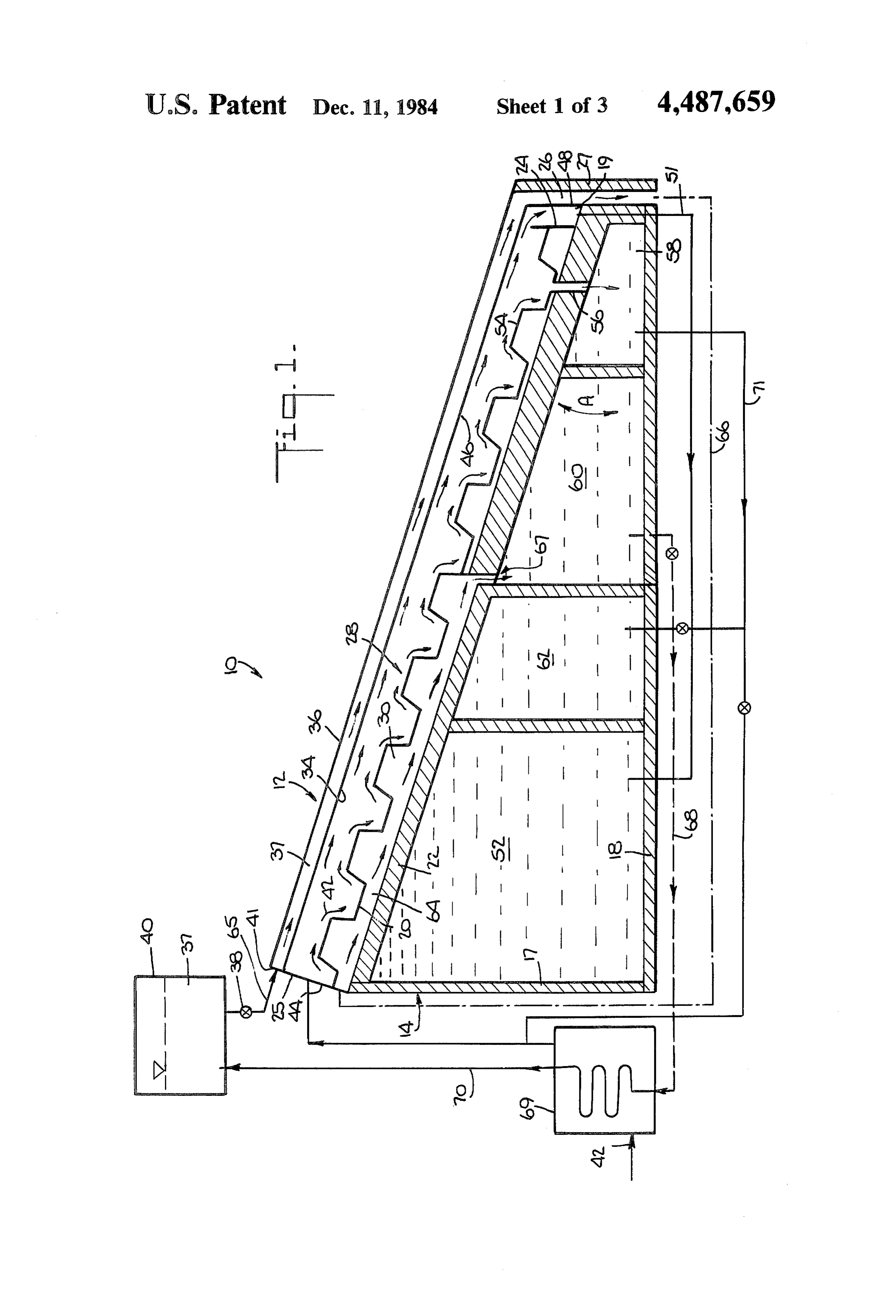
concentrating the solar energy on the means for con- 30 FIG. 1 is a cross-sectional elevation view through ducting. The fluid lens means in accordance with the distillation apparatus according to the present inven invention comprises a plurality of fluid lenses each hav tion;
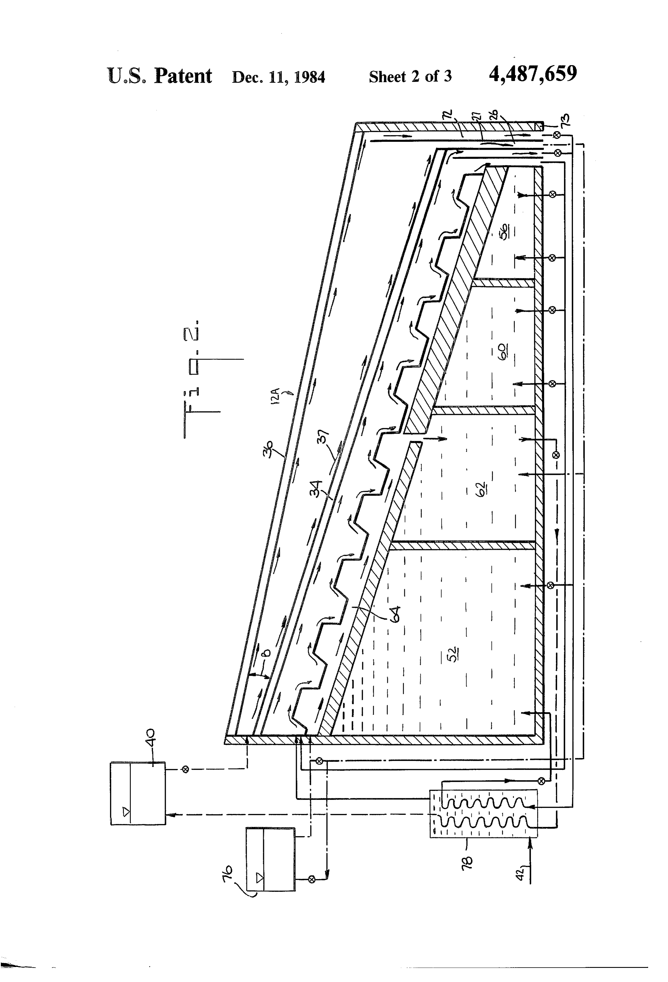
ing a focus and each being disposed above said means FIG. 2 is a cross-sectional elevation view through for conducting so that each said focus is located on or distillation apparatus according to another embodiment below said means for conducting. In the disclosed em- 35 of the present invention;
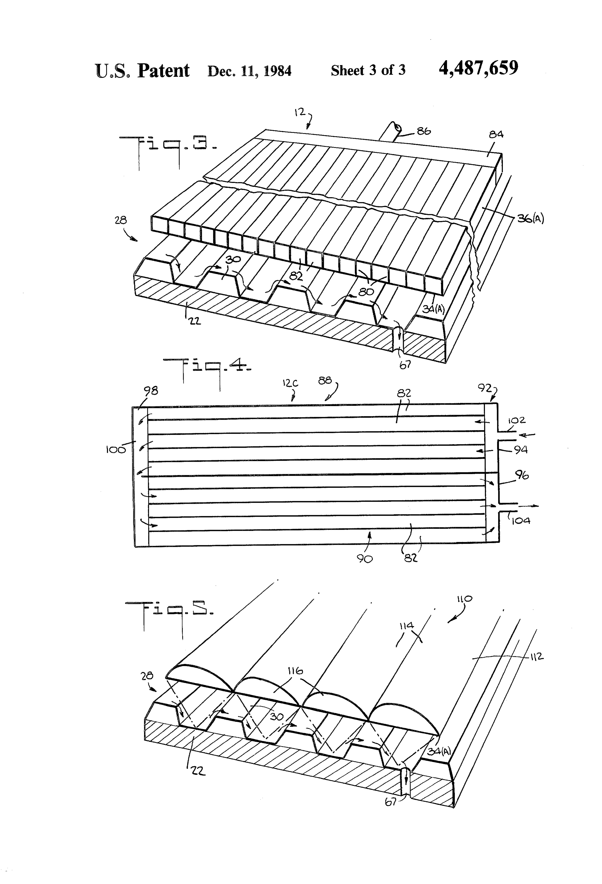
bodiments, the fluid lens means comprises a planar FIG. 3 is a perspective view in cross-section of distill lower plate and an upper plate having a plurality of lation apparatus, according to another embodiment of elongated, adjacently disposed convex portions, the the invention utilizing conduit means having a plurality upper and lower plates being spaced. Elongated, prefer of passages;
ably transparent supports may be disposed between the 40 FIG. 4 is a top view of conduit means similar to the upper and lower plates extending parallel to sides of conduit means of FIG. 3 showing a go-return flow adjacent convex portions. Each convex portion to arrangement; and gether with a portion of the bottom plate and associated FIG. 5 is a perspective view in cross-section of distil supports, where utilized, forms a conduit through lation apparatus according to another embodiment of which cooling fluid can flow. 45 the invention utilizing fluid lens means. The lower plate of the conduit means and the fluid DESCRIPTION OF THE PREFERRED lens means transfers heat released by the condensing EMBODIMENTS liquid so as to enable recovery of the heat of condensa tion released by the condensing liquid. Referring now more particularly to the drawings, In accordance with another aspect of the invention, 50 FIG. I. illustrates solar distillation apparatus 10 accord an array of photovoltaic cells can be disposed on the ing to one embodiment of the invention for distilling salt means for conducting at a location to receive concen water. Apparatus 10 includes a double plate conduit trated solar energy from the fluid lens means. System 12 supported by a base structure 14, having a In the disclosed embodiment, the liquid to be distilled front wall 17, a bottom wall 18 and a rear wall 19. On comprises water, typically sea water. Advantageously, 55 the base Structure 14 is disposed conducting means 20 the fluid passed through the conduit means comprises including an insulating base member(s) or panel(s) 22 distilled water, preferably the condensate of the water which rests on walls 17 and 19. The means for conduct being distilled. ing includes a bottom end wall 24 and a top end wall 25. According to another aspect of the invention, the The means for conducting 20 will, of course, have ap fluid passed through the conduit means can comprise 60 propriate side walls, not shown in FIG. 1. The double liquid to be distilled, the conduit means comprising plate conduit System 12 is supported by the base struc plates spaced by a distance exceeding the thickness of ture rear wall 19 and the conducting means upper wall the liquid flowing through the conduit means, with the 25. The double plate conduit includes an outlet conduit upper plate receiving liquid vapor thereon and condens 26 formed by wall 19 and a member(s) or panel(s) 27. ing the same. The condensed liquid is then collected so 65 Disposed on top of the insulating base member 22 is an as to provide additional condensate. undulated plate system 28 which can be made from a According to the embodiments of the invention single plate or from a plurality of plates. The height of which do not include a lens, substantially all of the solar each of the undulations 30 can be for example 90 mm
Page 8scan →
(about 3.5 inches). The distance between undulations for conducting is heated and evaporated, and impinges can be for example 120 mm (about 5 inches). The pla upon the lower plate 34 of the double plate conduit te(s) of the plate system is preferably made out of metal system 12. Condensate 46 runs down the lower surface such as steel, stainless steel or copper, having a thick of the lower plate 34 and is collected in compartment 48 ness of, for example 1 mm. It is preferred that the upper 5 formed by walls 19 and 24 from which it flows through surface of the plate system be covered by a black paint an opening 50 and a conduit 51 to a compartment 52 or chrone black. The paint or other agents should be located below the insulating base member 22. Brine 54 made of an anticorrosive material and provisions should which results from evaporation of water from the salt be made, if necessary, to provide cathodic protection flows through an outlet 56 of the plate system to a corn for the metal structure to prevent damage which could 10 partment 58 located below insulating base member 22. result from electrical currents caused by the reaction As the water being distilled flows over the undula between the metal surface and the existing chemicals in tions it will be in cavities which are only about 90 mm an electrolytic solution in the water. As an alternative deep. This depth of the water in the cavities between to metal, undulated asbestos fiber, glass or plastic plate the undulations 30 and the thin layer of water which can be used. However, metal is preferred as it will rela 15 flows over the undulations 30 will result in fast heating tively uniformly conduct heat to all sides of the plate and evaporation of the water. Since deposits can form system. on the plate system, a single panel or a plurality of The double plate conduit 12 includes a lower plate 34 adjacent panels made of blackened flexible plastic or the and a spaced upper plate 36 which are sealed to form like, such as isobutyl, can be used to cover the surface of the conduit. The space between the plates is shown the plate system and can be attached thereto in a remov exaggerated for clarity. One or more openings are pro able manner so that the plastic covering can be taken vided at each end of the double plate conduit in order to out and the deposits thereon removed. admit and withdraw fluid 37 from the conduit so as to As disclosed in Ser. No. 44,901, now U.S. Pat. No. allow for circulation of the fluid through the conduit 12. 4,323,052, a plurality of units such as unit 10 can be The openings may be provided by partially obstructed provided operating in Series and/or in parallel. the space along the extreme ends of the plates with In accordance with another feature of the embodi silicone or other means, leaving small outlets for pas ment of FIG. 1, storage areas are located beneath the sage of the fluid. This is done so as to allow the fluid to insulating base member 22. Shown is a storage area 58 spread in a thin layer substantially over all the interior for brine 54, a storage area 60 for the fluid 37 circulated surface area of the plates 34 and 36. A valve 38 at the 30 in the double plate conduit 12, another storage area 62 upper end of the double plate system permits selective for concentrated brine and a storage area 52 for the control of the flow of the fluid from a tank 40. The fluid condensate 46. By storing the various fluids beneath the will flow to the inlet 41 of the double plate conduit from insulating base member 22, further insulation and reten the tank 40, which is at a height of, for example, 40 cm tion of heat within the system is obtained. (about 17 inches) above the conduit 12 so as to allow 35 Circulation of the various fluids can be carried out in minimal pressure between the plates 34 and 36. the manner described in my aforementioned application The double plate conduit 12 and the conducting Ser. Nos. 915,001, U.S. Pat. No. 4,270,981, and 44,901, means are inclined at an angle, A. As shown, the con U.S. Pat. No. 4,323,052, and furthermore, as described duit 12 and the conducting means are parallel. How herein.
ever, the conduit could be at an angle slightly greater 40 In accordance with another aspect of the invention, than the means for conducting so as to provide for a the fluid 37 circulated between the double plate conduit larger volume between the conduit and the means for 12 is circulated, before being stored in the compartment conducting. In general, angle A is selected so that the 60, through a conduit 64 disposed between the upper double plate conduit and the conducting means are part of the undulated plate system in a heat exchanging inclined up to a maximum angle of about 25 with the 45 relationship therewith and the insulating base member horizontal. In certain locations and during certain sea 22. This allows for the transfer of heat from the col Sons, when at an angle of 25, the double plate conduit lected condensate to the salt water as it is conducted and the conducting means are normal to the rays of the over the undulated plate system. The fluid 37 flows Sun. In other locations, and during other seasons, when from the tank 40 through valve 38 and conduit 65 to the the conduit and conducting are at an angle of 25, the SO double plate conduit 12. The fluid 37 leaves the double rays of the sun will not be normal to the conduit and the plate conduit 12 through outlet conduit 26 and is con means for conducting but will strike them at some an ducted to the heat exchange conduit 64 below the plate gle. However, the rays will nonetheless be incident system 28 via conduit 66. From conduit 64, the fluid 37 upon the conduit and the means for conducting and will is conducted to compartment 60 by conduit 67. From therefore be collected. Accordingly, the angle of ap 55 compartment 60, the fluid is pumped back to tank 40 proximately 25 is selected so as to reduce the amount of through conduit 68, heat exchanger 69 and conduit 70. pressure required to circulate the fluid through the Heat can be transferred from fluid 37 to the water to be conduit 12 and correspondingly the conduit 12 does not distilled by means of heat exchange conduit 64 and heat have to be constructed so as to withstand high pres exchanger 68.
Sures. For example, disposing the system at an angle of 60 The lower plate 34 of conduit 12 is heated by the heat 25 instead of 45 provides for a reduction of pressure of of condensation released when the water vapor con water circulating between the plates of the double plate denses on that plate, and the plate transfers the released conduit 12 from about 30 cm to about 70 cm of water. heat to the fluid 37 circulating between the plates 34 and Salt water 42 is supplied to the means for conducting 36. Thus, most of the heat of condensation can be recov 28 via conduit 43 and opening 44 in the end wall 25. The ered. The lower plate 34 is also heated by the heat of Salt water cascades over the undulations 30 and receives radiation from the undulated plate system over which the Solar energy transmitted through the double plate water is cascading, and also by the heat convected from conduit 12. The salt water conducted over the means the mass of vapor and air flowing towards the double 9 plate conduit 12. The solar rays transmitted through the between the plates. It is also possible to eliminate the transparent double plate conduit are partially absorbed upper plate 36 altogether. The system of FIG. 2 oper by the fluid 37 flowing between the plates. The fluid ates similar to that of FIG. 1 except that the double flowing through the double plate conduit 12 can be plate conduit 12A essentially need not be pressurized. heated to selected temperatures by regulating the flow 5 Instead, the fluid flowing in the conduit is merely con of fluid therethrough. For example, the fluid 37 can be ducted over the lower plate 34.
distilled water, and, for a water vapor temperature up to The upper plate 36 may be parallel to or disposed at 75 C., water entering at 25 C. can be heated to 65 C. an angle to the lower plate 34. As shown in FIG. 2, the at the outlet. The quantity of water required to recover upper plate 36 is disposed at an angle with the lower the heat of condensation for a temperature change of 10 plate 34. The upper plate 36 extends beyond the lower 25 C. to 65° C., i.e., a difference of 40 C., will be about plate 34 and an additional compartment 72 formed by eight times the quantity of water condensed for an effi walls 27 and 73 is provided below the lower end of the ciency of, for example, 60%. To recover 60%, the 540 upper plate. Wall 27 separates compartment 72 from cal/liter released by the condensing vapor requires 8.1 outlet 26. The arrangement in FIG. 2 allows for the times the quantity of water to absorb that released heat 15 evaporation and condensation of liquid 37 circulated for a 40° C. change as follows: (0.6)(540)/40=8.1. This between the double plate conduit system. The evapo heat can heat a quantity of water to be distilled from 20 rated liquid can condense on the lower surface of upper C. to 55 C., a 35° C. difference, at 90% efficiency, plate 36 and the condensate can flow along the lower which is 8.3 times the quantity of water condensed as surface to be discharged into the compartment 72. Ad follows: (0.9)(324)/35= 8.3, where 324 represents 60% 20 vantageously, the liquid circulated between the double of 540. plate system in FIG. 2 is water to be distilled so that the The water 37 circulated in conduct 64 below the condensate obtained is distilled water which can be undulated plate system which is at about 65 C. will mixed with the condensate collected from the lower heat the incorning water to be distilled from about 30 surface of the lower plate 34. The vapor produced by C. to about 50 C. This will also act to cool the water 37 25 the water flowing between the double plate conduits flowing through conduit 64 from about 65° C. to about will be heated for example to about 65° C. The water 50° C., for example. After the water 37 is conducted vapor will be condensed on the bottom of plate 36 pro through conduit 64 under the undulated plate System, it ducing additional condensate at 50 C, for example. The can be passed through a heat exchanger 69 to further hot condensate will also be used together with the con preheat the water 42 to be distilled from 20° C. to about 30 densate from the lower plate to preheat the incoming 30° C., for example. The water 37 will be cooled to distilled water, as described in connection with FIG. 1. about 25 C. and can then be stored in the compartment Another advantage of the arrangement in FIG. 2 is 60 under the insulating base member 22. In other words, the reduction of heat losses by radiation and convection part of the heat recovered by the water 37 between the by virtue of the spaced upper plate 36. The temperature plates 34, 36 of the conduit 12 will heat incoming water 35 of the upper plate will be lower than that of closely 42 to be distilled through the metallic bottom plates of spaced parallel plates by possibly 20° C. to 50° C. To the plate system 28, and part of the heat will preheat the this effect, the top and bottom plates may form an angle water to be distilled in the heat exchanger 69. This will B of, for example, 8, thus increasing the insulating allow a reduction of the quantity of water 37 which has space between the two plates. This system does not to be introduced into the conduit 12 of the apparatus by 40 have to withstand high pressures and the perimeter of 2/3, i.e. only five times instead of eight times the quan the top and bottom plates need only hold the water. tity of water directly vaporized will have to flow Two tanks or reservoirs will preferably be supplied through the conduit 12. This arrangement also allows a for the fluids, one tank (76) for the fluid collected at 70 decrease in the height of the water 37 necessary to C. and one tank (40) for the fluid collected at 25 C. The circulate the water between the plates 34, 36 of conduit 45 use of tank 76 reduces pressure requirements for con 12. duit 64.
In the embodiment illustrated in FIG. 1, the plates 34 A double coil heat exchanger 78 provides for heating and 36 are spaced by a distance which corresponds to of the water 42 to be distilled by the fluid 37 and the the desired thickness of the fluid 37 to be circulated condensate. While double heating of the water to be between the plates. The system in FIG. 1 can be pres- 50 distilled is preferred, it is not indispensable. sured. However, the amount of pressure the system has Compartment 52 is for condensate from plate 34 and to withstand is relatively low as the angle of inclination 36; compartment 62 is for fluid 37; and compartments 60 is maintained to be less than or equal to about 25. and 56 are for brine.
The brine 54 entering compartment 58 may be con If desired, the fluid circulated in conduit 12 can be ducted to compartment 62 via conduit 71. The brine 5 5 mixed with products such as glycol. may be introduced into the means for conducting 20 via Referring now to FIG. 3, the double plate conduit conduits 71 and 43 so as to recover the heat in the brine, 12B may comprise a plurality of elongated adjacently i.e. utilize the heated brine to heat incoming salt water. disposed upper plates 36A or a single upper plate 36, Heat can also be recovered from the condensate by a and a corresponding plurality of lower plates 34A or heat exchanger, for example, not shown in FIG. 1. This 60 single lower plate 34. A plurality of transparent elon recovered heat can also be used to heat the water to be gated supports 80 can be disposed between the (individ distilled. ual) upper and lower plates to form individual passages Valving is provided as necessary to obtain the flows or conduits 82 through which the fluid is passed. Where described herein. individual plates are employed, the supports can be The embodiment illustrated in FIG. 2 is similar to the 65 disposed at the intersection of adjacent plates. The embodiment in FIG. 1 except that the double plates 34 lower plate or plates, as in the embodiments previously and 36 of the conduit 12A are spaced by a distance described, will act to transfer the heat of condensation greater than the thickness desired of the fluid 37 flowing to the fluid being circulated between the plates. Each of 10 the conduits 82 may be communicated at each end with could be made to the embodiments of the invention a common conduit 84 having an inlet 86 as in FIG. 3, SO herein chosen for the purpose of the disclosure without as to provide for a single collector compartment with departing from spirit and scope of the invention. all the conduits 82 being connected in parallel. All the What is claimed is:
fluid passes through double plate conduit 12B and over 5 1. Apparatus for distilling liquids utilizing solar en the plate system 28 once. Where the fluid is distilled ergy comprising:
water, it can be heated from about 25 C. to about 40 (a) means for conducting the liquid to be distilled at C., for example. an acute angle with respect to the horizontal; In FIG. 3, the conduits 82 are shown running parallel (b) conduit means transparent to visible light for con to the undulations 30. The conduits 82 may be arranged 10 ducting a liquid therethrough in a heat exchange to run longitudinally in the apparatus, i.e., perpendicu relationship with the conduit means, the conduit lar to the undulations. means being disposed above said means for con In FIG. 4, the individual conduits 82 of double plate ducting so as to conduct liquid therethrough at an conduit 12C are connected in a go-return arrangement. acute angle with respect to the horizontal generally Double plate conduit 12C is divided into two compart 15 in the same direction as the liquid conducted by the ments 88 and 90. The conduits 82 of compartment 88 are means for conducting and allow solar energy to connected together at one end 92 by conduit 94 and the pass through said conduit means and be received conduits 82 of compartment 90 are connected together without substantial concentration in or on the at the same end 92 by conduit 96. At the other end 98 of means for conducting;
the double plate conduit 12C, all the conduits 82 are (c) means supplying liquid to said conduit means for connected together by conduit 100. An inlet 102 is pro assisting the condensation on said conduit means of vided for compartment 88 and an outlet 104 is provided liquid evaporated from said means for conducting for compartment 90. Fluid flows in one direction in and absorbing heat released by the condensing compartment 88 and in the opposite direction in com liquid, the supplying means providing sufficient partment 90. Compartments 88 and 90 are thus con 25 liquid to the conduit means and the conduit means nected in series and fluid passing through conduit 12C being structured such that a substantial amount of can be heated to a higher temperature. Distilled water, liquid passes through the conduit means unevapo for example, entering compartment 88 at 25 C., for rated and absorbs heat released by the liquid con example, can be heated to 40° C. as the fluid passes over densing on the conduit means while assisting the the plate system a first time in one direction. the 40 C. condensation on said conduit means of liquid evap water introduced into compartment 90 can be heated to orated from said means for conducting; and 60° C., for example, as it passes over the plate system a (d) means for collecting the condensed liquid. second time in the opposite direction. As in FIG. 3, the 2. Apparatus in accordance with claim 1 wherein the conduits 82 may be parallel or perpendicular to the undulations. 35 means for conducting and the conduit means are gener According to another embodiment of the invention, ally elongated and generally coextensive. the double plate conduit system may be replaced by 3. Apparatus in accordance with claim 1 wherein the fluid lenses 110 which include an upper plate 112 made conduit means comprises a double plate conduit having upper and lower plates transparent to visible light, the up of a plurality of convex sections 114 and a single upper and lower plates being spaced to permit a thin lower plate 34 or a corresponding plurality 34A of 40 lower piates. The convex portions 114 of the upper flow of liquid therebetween, the lower plate being dis plate can be arranged so as to form a plurality of fluid posed above the means for conducting so as to provide lenses, each forming an individual conduit 116 for the space therebetween.
flow of fluid therethrough. For example, the convex 4. Apparatus in accordance with claim 1 wherein the portions can be 16 cm wide and spaced by approxi 45 conduit means comprises a plate transparent to visible mately 6 cm at the point of widest separation. The indi light disposed above the means for conducting so as to vidual fluid lenses can concentrate the solar energy into provide space therebetween, and means disposed about the valleys between the undulations 30 on the plate the perimeter of the plate for forming in cooperation system over which the water to be distilled is cascading. with the plate an enclosure for liquid flowing on the This will provide higher temperatures for heating the plate.
water and can provide for faster evaporation in the 5. Apparatus in accordance with claim 3 or 4 and areas in which the solar energy is concentrated. The comprising means cooperating with the lower of said radius R of the fluid lenses can be for example: plates for closing off said space.
R = (d+ L2/4d), where L is the aperture of the fluid 6. Apparatus in accordance with claim 4 and compris lens and d is the spacing at the point of widest separa 55 ing another plate transparent to visible light disposed tion between the upper and lower plates. The focal above said plate so as to form a double plate conduit. distance is defined by F = R/N-1, where N is the re 7. Apparatus in accordance with claim 6, wherein the fractory index (1.45 for example). R can then be calcu plates are spaced by a distance so as to exceed substan lated to be equal to 8.3 cm and F to be equal to 18 cm. tially the depth of the liquid flowing between the plates If desired, an array of photoelectric cells may be 60 and allow liquid to be evaporated between the plates disposed in valleys between undulations where the fluid and condense on an upper of the two plates. lens concentrates the solar energy as described in Ser. 8. Apparatus in accordance with claim 7 and compris No. 44,901 now U.S. Pat. No. 4,323,052. ing means for collecting liquid condensed on the lower The advantages of the present invention, as well as surface of said upper plate.
certain changes and modifications of the disclosed em 65 9. Apparatus in accordance with claim 7 wherein the bodiments thereof, will be readily apparent to those plates are parallel.
skilled in the art. It is the applicant's intention to cover 10. Apparatus in accordance with claim 7 wherein by his claims all those changes and modifications which the plates form an acute angle.
Page 11scan →
11. Apparatus in accordance with claim 1 wherein direction as the liquid conducted by the means for said means for conducting comprises an undulated plate conducting;
system. (c) means supplying liquid to said fluid lens means for 12. Apparatus in accordance with claim 11 wherein assisting the condensation on said fluid lens means said plate system has undulations with a depth on the 5 of liquid evaporated from said means for conduct order of up to 90 mm separated by approximately by ing and absorbing heat released by the condensing 120 mm. liquid; and 13. Apparatus in accordance with claim 1 wherein (d) means for collecting the condensed liquid. said means for collecting the condensed liquid includes 22. Apparatus in accordance with claim 21 and com a compartment which is disposed below a portion of 10 prising an array of photovoltaic cells disposed on Said said means for conducting. means for conducting at a location to receive concen 14. Apparatus in accordance with claim 13 and com trated solar energy from said fluid lens means. prising heat exchange means connected to said con 23. Apparatus in accordance with claim 22 and fur partment for transferring heat to the liquid to be dis 5 ther including means encapsulating said array and means Supplying a cooling fluid to said encapsulating tilled before the liquid is conducted over said means for means conducting. to cool said array. 15. Apparatus in accordance with claim 1 and further 24. Apparatus in accordance with claim 1 wherein comprising means for collecting the liquid conducted Said conduit means comprises parallel upper and lower over said means for conducting, said means for collect plates spaced by elongated supports, the elongated sup ing being disposed below a portion of said means for ports and the upper and lower plates forming individual passages for liquid to be passed through the conduit conducting. eaS.
16. Apparatus in accordance with claim 15 and 25. Apparatus in accordance with claim 24 and in wherein said means for collecting comprises a compart cluding ment, said apparatus including means connecting Said 25 provide means a for connecting said passages so as to parallel liquid flow through said conduit compartment with said means for conducting for sup means in one direction.
plying liquid in said compartment to said means for 26. Apparatus in accordance with claim 24 and in conducting. cluding means for connecting said passages so as to 17. Apparatus in accordance with claim 1 and con prising means for collecting the liquid conducted provide a serial liquid flow through said conduit means through said conduit means, said means for collecting in opposed directions, being disposed below a portion of the means for con said27.liquid Apparatus in accordance with claim 1 wherein to be distilled comprises water.
ducting. 28. Apparatus in accordance with claim 27 wherein 18. The apparatus in accordance with claim 1 or 17 said liquid passing through the conduit means comprises comprising heat exchanging means connected to said 35 distilled water.
conduit means and to a source of liquid to be distilled,
Said heat exchange means transferring heat from the said29.distilled Apparatus in accordance with claim 28 wherein liquid passing through the conduit means to the liquid to said water towater comprises condensate obtained from be distilled, said apparatus also including be distilled, the heat exchanging means including means means for cooling said condensate prior to supplying for connecting the heat exchanging means to the means 40. the condensate to said conduit means. for conducting to transfer thereto liquid to be distilled. 30. Apparatus in accordance with claim 27 wherein 19. Apparatus in accordance with claim 1 or 17 corn said liquid comprises water to be distilled. prising additional conduit means disposed below said 31. Apparatus in accordance with claim 11 and fur means for conducting and in a heat exchanging relation ther including an insulating base member below said ship therewith. 45 plate systern.
20. Apparatus in accordance with claim 9 and com 32. Apparatus in accordance with claim 31 and fur prising means connecting said additional conduit means ther including at least one storage means disposed and Said conduit means for conducting said liquid below said insulating member for storing fluids used in through said additional conduit means. said apparatus.
21. Apparatus for distilling liquid utilizing solar en 33. Apparatus in accordance with claim 32 wherein ergy comprising: said plate system is made out of a metal selected from (a) means for conducting the liquid to be distilled at the group consisting of stainless steel, steel and copper. an acute angle with respect to the horizontal; . Apparatus in accordance with claim 11 wherein (b) fluid lens means disposed above said means for said piate system is covered with an anticorrosive mate conducting for concentrating solar energy on the 55 rial.
means for conducting, said fluid lens means con 35. Apparatus in accordance with claim 11 and fur prising a planar lower plate and an upper plate ther including a blackened flexible material disposed having a plurality of elongated convex sections, the over at least part of said plates in a manner such that it upper and lower plates being spaced, and elongated is removable to permit removing deposits therefrom. supports being disposed between the upper and 60 36. Apparatus in accordance with claim 3 and includ lower plates extending parallel to sides of adjacent ing a tank filled with said liquid connected with and convex sections, each convex section together with disposed above said conduit means so as to supply liquid a portion of the bottom plate and the associated to said conduit means at substantially low pressure. supports forming a conduit through which a liquid 37. Apparatus in accordance with claim 19 and in can flow in a heat exchange relationship with said 65 cluding a tank filled with said liquid connected to and lower plate, said fluid lens means being disposed to disposed above said additional conduit means so as to conduct the liquid therethrough at an acute angle Supply liquid to Said additional conduit means at sub with respect to the horizontal generally in the same stantially low pressure.
Page 12scan →
38. Apparatus in accordance with claim 1 and includ- liquid being distilled has been conducted over the ing heat exchange means for transferring heat from the means for conducting.
condensate of the liquid to the liquid to be distilled. 40. Apparatus in accordance with claim 1 wherein 39. Apparatus in accordance with claim 1 and includ ing means for introducing a concentrate of the liquid 5 said direction is downwardly inclined. being distilled into the means for conducting after the . . . .
Provenance
- Collection
- Patents citing this work
- Pages
- 12
- Method
- pdftotext (the PDF's own text layer) + pdftoppm 300dpi page scans
- Patent office record
- patents.google.com →
- Source
- Google Patents citing-documents table
- Assignee
- North American Utility Construction Corp.
- Published
- 1984-12-11
- Transcribed from
- patentimages.storage.googleapis.com →