

patent · US4086911A
Solar heating device
2 May 1978
Text
Page 1bibliographic recordscan →
United States Patent (19)
Futch
(54). SOLAR HEATING DEVICE
76 Inventor: Wilbur O. Futch, P.O. Box 947,
Brandon, Fla. 33511
51 Int. Cl? ............................ F24J 3/02; F24H 7/00 52 U.S. C. .................................... 126/271; 126/270;
Field of Search ....................... 126/270, 271, 400;
1,747,826 2/1930 Gould .................................. 126/271 1,969,187 8/1934 Schutt ...................................... 165/2 2,167,576 7/1939 Kiser .................................... 126/271 2,213,894 9/1940 Barry .................................... 126/271 3,107,052 10/1963 Garrison .............................. 237/1 A 3,250,269 5/1966. Sherock .......................... 237/1 AX 3,902,474 9/1975 Pyle ................................. 26/271 X 3,929,122 12/1975 Alkasab ................................ 126/271 Primary Examiner-Kenneth W. Sprague
Assistant Examiner-Larry Jones
Attorney, Agent, or Firm-Stein & Frijouf
A solar heating system is disclosed of the type used to heat hot water or like fluid for domestic or industrial use comprising a collector assembly including fluid storage facilities formed on the interior thereof and exterior portion surrounding the fluid storage facilities. A collector unit including a coil element wound contin uously about the exterior portion and disposed to define part or all of the exposed surface of the exterior portion wherein this exterior portion further is arranged at an angular orientation between a base and head segment of the collector assembly. A transparent or light permea ble casing surrounds the entire collector assembly wherein the entire collector assembly is connected in fluid communicating relation with a preheater assembly which includes a fan and is preferably mounted in an attic or other environment wherein the surrounding temperature is greater than ambient temperature.
7 Claims, 4 Drawing Figures
Drawings
Page 2drawing sheetscan →
Page 3scan →
at the same time unreliable and expensive to maintain
Background of the invention
All of the above problems which are adequately rec ognized in the solar heating industry can be summarized 1. Field of the Invention 5 in the following categories (1) inefficiency of operation This invention relates to a solar water heater of the in heating the liquid or other fluid to the desired temera type designed to be mounted on the roof or adjacent an ture or temperature range, (2) maintaining the liquid at attic portion of the building such that a preheater assem the desired temperature and enabling heat transfer in a bly in the form of a supplementary collecting coil can be manner which is efficient, (3) consuming a relatively disposed in direct air flow from the attic or like room 10 small amount of time and providing reliable operation which would normally maintain a temperature greater even in inconsistent weather conditions. than ambient. The preheater assembly is connected in Accordingly, there is a need in the water heating fluid communication with the main solar energy collec industry for a solar water heater of improved design and tor assembly which has a fluid storage facility mounted structure which operates effectively and efficiently to on the interior thereof, the collector assembly being 5 accomplish a desired purpose.
specifically shaped to obtain optimum exposure to the SUMMARY OF THE INVENTION sun's radiation based upon its predetermined position ling. This invention relates to a fluid solar heating system 2. Description of the Prior Art primarily designed to be mounted on the exterior of a Solar heating systems have long been known as a 20 building structure adjacent the roof and/or attic por method of obtaining hot water or other fluids without tion. More specifically, the system comprises an energy the use of traditional fuels. Generally, such heating collector assembly disposed in direct exposure to the systems have been utilized for the purpose of attempting sun's rays and energy. A preheater assembly is also to reduce or eliminate heating cost by eliminating the provided in direct fluid communication with the energy need or at least lessen the demand for such traditional 25 collector assembly. A conventional source of liquid fuels. Numerous prior art systems have been utilized in such as from the main water supply of a city or commu industry and are also now commercially available. nity is channeled first into the preheater assembly and However, even though solar heating systems have then after being heated, as will be explained in greater been known and been in practice for some time, there detail hereinafter, is then transferred to the main or are recognized inherent disadvantages found in these primary energy collector assembly which, as set forth prior art systems. Many of these known devices are above, is disposed in direct exposure to sunlight. generally not self-contained and fluid flow through the The primary or main energy collector assembly com entire system is primarily dependent upon line pressure prises a fluid storage means in the form of a tank having of the fluid to force the fluid through the coils of the the heated liquid stored in the interior thereof. An exter heat exchanger. While such line pressure problems have 35 nal portion is disposed in surrounding relation to the been recognized, perhaps the greatest problems associ storage means and includes a collector unit in the form ated with the solar heating industry is efficiency of of a coil defining at least a portion of the exterior of said operation or performance capabilities. This problem of storage means. The collector assembly comprises a inefficiency is generally blamed on a number of struc head and a base portion disposed such that the exterior tural features of the prior art system ranging from im 40 portion with the coils and the remainder of the unit is proper installation to inefficient heat collecting plates, mounted thereon is substantially angular oriented to etc. Generally, the basic structure of known solar heat- . both the base and the head portion. This inclined orien ing systems includes some type of collector plate ex tation of the external portion substantially defines a posed to the direct rays of the sun wherein the collector frustoconical configuration of the collector assembly. plate comprises tubing through which water or liquid to 45 In one embodiment of the present invention the exter be heated flows. Theoretically, the sun's energy is ab nal or exposed surface of the energy collector assembly sorbed into the coils in the form of heat and transferred may have mounted thereon and accordingly defining a to the liquid. The liquid is then stored in a storage tank part thereof of the coil means itself. The coil is wrapped of normal conventional design. A number of the exist continuously around the external portion so as to ac ing systems further cause forced circulation to occur at 50 complish maximum exposure to the sun's rays. The coil a constant or periodic basis dependent upon the temper extends from an inlet point which is directly connected ature of the water desired and the difference in this to the preheater assembly to the point where the heated temperature from the water being maintained in any water is dispensed directly into the storage means. In storage tank or facility. While functional, this type of this embodiment the coil means is mounted on a collec arrangement does not always result in maximum operat 55 tor plate made of heat conductive material so as to ing efficiency. accomplish maximum heat transfer from the coil and Another problem commonly present in the prior art collector plate to the fluid traveling or maintained and recognized in the heating industry is the existence within the coil means. For added efficiency both the oftemperature sensors which are forced to be located in external surface portion of the collector plate and the direct contact with the fluid flow in which therefore coil may be blackened so as to absorb maximum radia impair the flow of liquid through the coils. Temperature tion.
sensors are also utilized in prior art devices as a mechan In yet another embodiment of the present invention ical means to regulate the flow of fluid dependent upon the coil means may be disposed in intimate contact with the particular desired temperature or arrangement of adjacently positioned portions so that the entire exter temperatures intended for adequate operation of the 65 nal surface is made up of the commonly engaging and system. While such temperature sensors are, of course, continuously formed coils.
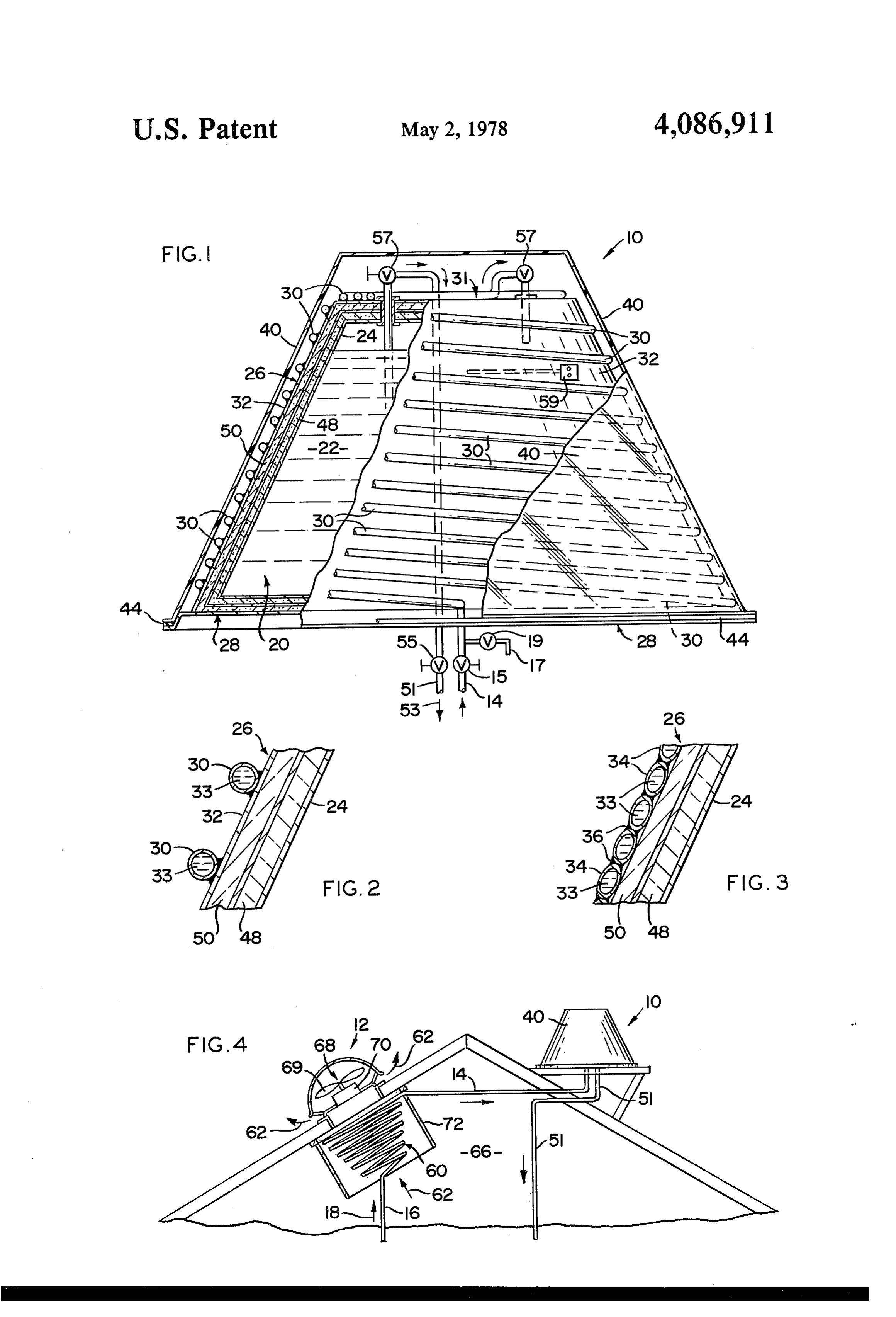
necessary and frequently utilized, overly complicated In this embodiment the exposed surface of the coils sensors are frequently considered to be unnecessary and which, of course, defines the exposed surface of the 4 external portion may be blackened to accomplish maxi FIG. 3 is a detail view in partial cutaway and section mum efficiency. showing yet another embodiment of the present inven Turning to the structure of the preheater assembly, a tion directed to the coil means. supplementary coil means which contains liquid passing FIG. 4 is a schematic view showing direction of fluid directly from the conventional source of liquid or water flow from a liquid supply, through a preheater assembly is positioned in an attic or like area of the building struc and finally to and from the energy collector assembly. ture which is normally maintained at a higher tempera Similar reference characters refer to similar parts ture due to the fact that heat naturally rises. An air throughout the several views of the drawings. directing means is disposed in air flow regulating posi DETAILED DESCRIPTION tion, immediately adjacent to the supplementary coil. 10
This air directing means may take the form of a fan and With reference to FIG. 4 the fluid heating system may be positioned on either side of the coil, either up includes an energy collector assembly generally indi stream or downstream, so that it may establish air flow cated as 10 connected in fluid communication to a pre heater assembly generally indicated as 12. Fluid inter from the attic, over the supplementary coil and vent the 15 connection between the energy collector assembly 10 directed, normally heated air to atmosphere. Heat and the preheater assembly 12 takes place by conven therefore will naturally collect and be transferred to the tional conduit or piping 14. Similarly, piping 16 directs liquid maintained or passing through the supplementary coil. It is therefore further obvious that the heat passing water or other liquid from a conventional fluid supply upwardly through conduit 16 into the preheater assem to the coil means associated with the energy collector 20 bly as indicated by directional arrow 18. assembly is preheated to the temperature of the air normally maintained in the attic or compartment where bly 10 comprises tofluid
With reference FIG. 1 the energy collector assem storage means generally indi the preheater is located. Temperatures in the attics of cated as 20 including heated water or fluid 22 main the average domestic or industrial building reach amaz tained in tank 24 which comprises a portion of the fluid ingly high temperatures and substantial benefit is ob 25 storage means. The energy collector assembly 10 fur tained in incorporating a solar collector assembly with ther comprises an external portion 26. The external such a preheater assembly as set forth above. portion comprises a continuous side wall extending at Other structural features of the present invention may an angular orientation between a base portion 28 and a comprise proper insulating means maintained between head portion 31. This angular inclination and continu the collector plate and coil means and the storage facil 30 ous configuration define a frustoconical shape of the ity itself so as to maintain efficient and effective heat energy collector means as clearly represented in both transfer from the solar radiation collected by the energy FIGS. 1 and 2.
collector assembly. To enhance this collection, a casing The external portion has a collector unit mounted means, which may be correspondingly configured in a thereon. This collector unit comprises coil means 30 frustoconical configuration corresponding to the en 35 and collector plate 32 which together define the exter ergy collector assembly is disposed in surrounding rela nal surface of the external portion of the energy collec tionship thereto. This casing means is formed of a trans tor assembly as shown in the embodiment of FIGS. 1 parent material or a material capable of allowing the and 2. Both plate 32 and coil means 30 may be made sun's radiation to pass therethrough. s from a copper or like heat conductive material wherein In addition, proper valving is associated with the fluid 33 maintained or passing through coil means 30 has water inlets and outlets leading in the fluid path defined the heat transferred thereto. Such heat, as in conven from the conventional source of fluid supply, through tional systems, is collected by the plate 32 and the coil the preheater assembly and finally to and from the en means 30 and thereby transferred to the fluid 33. ergy collector assembly exposed to the sun's radiation. 45 In the embodiment shown in FIG. 3 the external Other devices including a bleed vent or cock commu surface is defined entirely by the plurality of coil means nicating with the coil means of the energy collector 34 disposed in intimate side-by-side engagement with one another as at junction 36. Irrespective of the em assembly may be provided. Similarly, a heat sensing bodiment utilized as shown in FIGS. 2 and 3 both the means may be properly located on the collector plate coil means 30 and/or 34 and the plate 32 may be black and/or in direct contact with the water being stored in 50 ened the storage means as described above. to effectively aid in the collecion of radiation in The invention accordingly comprises the features of in FIGS. of the form heat. Irrespective of the embodiment shown construction, combination of elements and arrangement tinuous path of3 fluid 2 or the coil means essentially forms a con flow about the external surface of of parts which will be exemplified in the construction the external portion 26.
hereinafter set forth, and the scope of the invention will 55 Another structural feature of the present invention be indicated in the claims. comprises casing means 40 having a generally corre BRIEF DESCRIPTION OF THE DRAWINGS sponding frustoconical configuration as the remainder For a fuller understanding of the nature and objects of the energy collector assembly. The casing means 40 of the invention, reference should be had to the follow is formed from a transparent or like material permeable to the sun's radiation. Rubber sealing may be placed as ing detailed description taken in connection with the at 44 to help seal the casing means about the energy accompanying drawings in which: collector assembly. The relationship between the casing FIG. 1 is a cross-sectional view in partial cutaway and the collector assembly is such as to raise the temper showing the interior and various exterior portions of the ature on the interior of the casing means thereby aiding energy collector assembly of the present invention. 65 in heat transfer to the liquid 33 within coil means 34. FIG. 2 is a, partial cutaway view in section of one In order to effect optimum or maximum heat transfer embodiment of the coil means associated with the col proper insulation means 48 and 50 is disposed between lector plate of the present invention. the outer wall tank element 24 and the backing plate 32.
Page 5scan →
Water inlet means occurs through conduit 14 and to said fluid storage means; said energy collector assem proper Valving arrangements 15 as shown. Vent means bly including a base portion and a head portion, said and release valve 17 and 19 are supplied and/or inter exterior portion and said collector unit disposed thereon connected in the manner shown in FIG. 1. Similarly, in angular orientation between said base portion and outlet conduit 51 travels through the storage means or said head portion and at least partially defining a prede tank 24 in the direction indicated by directional arrrow termined configuration, casing means substantially cor 53 and is regulated by proper valving assemblies 55. respondingly configured to said exterior portion of said Similar flow regulating valve means 57 may be supplied energy collector assembly disposed in at least partially as shown in FIG. 1 to help regulate the flow of liquid surrounding relation to said energy collector assembly, into and out of the storage means 20 comprising the 10 said casing formed at least in part from light permeable storage tank 24. Adequate heat sensing means 59 may be material, whereby solar radiation passes through said mounted either on the external surface of the collector casing means to impinge on said collector unit when assembly as on plate 32 or may be disposed in direct exposed to ambient solar radiation. fluid contact with the liquid 22 within the storage 2. A fluid heating system as in claim 1 wherein a collector plate means is mounted on said exterior por
As shown in FIG. 4 the preheater assembly com tion and disposed in supported relation to said coil prises a supplementary coil 60 fed from conventional means thereon, said collector plate means being dis water supply through conduit 16. Air flow is repre posed in angular orientation between said base portion sented by directional arrow 62 is caused to pass over the and said head portion.
supplementary coil from the attic space 66 by the flow 20 3. A fluid heating system as in claim 2 wherein said directional means 68 which may be in the form of a fan coil means is mounted on said plate means in spaced 69 operated by a conventional fan motor 70. Tunnel relation to one another and defining the external surface means 72 may be provided in substantially surrounding of said exterior portion at least in part with said plate relation to the supplementary coil 60 so as to help regu e2S.
late the flow of heated air from attic space 66 over the 25 4. A fluid heating system as in claim 1 wherein said supplementary coil.
It will thus be seen that the objects set forth above, coil means is disposed on said exterior portion in en among those made apparent from the preceding de of said coilwith gagement immediately adjacently disposed others scription, are efficiently attained, and since certain face of said exteriora portion means, major portion of the external sur defined by said commonly changes may be made in carrying out the above method 30 and article without departing from the scope of the engaging coil means.
5. A fluid heating system as in claim 1 wherein said invention, it is intended that all matter contained in the energy collector assembly comprises fluid inlet means above description shall be interpreted as illustrative and interconnected between the fluid supply and said fluid not in a limiting sense. storage means; fluid outlet means interconnected be It is also to be understood that the following claims 35 tween said fluid storage means and a fluid defining are intended to cover all of the generic and specific point; valving means interconnected in fluid regulating features of the invention herein described, and all state ments of the scope of the invention, which, as a matter relation with both said inlet and outlet means; said en of language, might be said to fall therebetween. Now ergy collector assembly comprising a sensing means interconnected between said collector unit and said that the invention has been described,
What is claimed is: valving means, whereby flow of fluid into said fluid 1. A fluid heating system of the type utilizing solar storage means is regulated through regulation of said energy as a heating source, said heating system compris valving means by said heat sensing means. ing: an energy collecter assembly having a frustoconical 6. A fluid heating system as in claim 1 further com configuration and including fluid storage means config 45 prising a preheater assembly disposed in fluid communi ured to have fluid stored on the interior thereof; said cation between the fluid supply and said fluid storage energy collector assembly further comprising an exte means, said preheater assembly further comprising sup rior portion, a collector unit mounted on said exterior plementary collector means, air flow directing means portion in substantially segregated and insulated rela disposed adjacent said supplementary collector means, tion to said fluid storage means, said collector unit com 50 whereby said preheater assembly is disposed in air flow prising coil means disposed on the exterior surface of having a greater temperature than ambient. said exterior portion and defining at least in part a sub 7. A fluid heating system as in claim 1 wherein said air stantially continuous path of fluid flow from a fluid flow directing means comprises a fan disposed to estab supply to said fluid storage means, said collector unit lish air flow over saidk supplementary collector means. being in at least partial surrounding relationship relative 55 is k sk
Provenance
- Collection
- Patents citing this work
- Pages
- 5
- Method
- pdftotext (the PDF's own text layer) + pdftoppm 300dpi page scans
- Patent office record
- patents.google.com →
- Source
- Google Patents citing-documents table
- Assignee
- Futch Wilbur O
- Published
- 1978-05-02
- Transcribed from
- patentimages.storage.googleapis.com →