

patent · US4089325A
Solar heated boiler
16 May 1978
Text
Page 1bibliographic recordscan →
United States Patent (19)
Broa
54 SOLAR HEATED BOILER
75 Inventor: Gabriel Brola, Nogent-sur-Marne,
France Assignee: Entreprise Industrielle de
Chaudronnerie, France
30 Foreign Application Priority Data
Jul. 18, 1975 France ................................ 75 22:510 Int. Cl’................................................. F24, 3/02 52 U.S. C. ....................................... 126/271; 60/641
842,658 1/1907 Haskell ................................. 126/271
1,425,174 8/1922 Carter et al. ........................ 126/27 1,951,403 3/1934 Goddard .............................. 126/271 3,208,447 9/1965 Laszlo .................................. 126/270 3,985,116 10/1976 Kapany ................................ 126/271 3,996,917 12/1976 Trihey ..... ... 126/271 4003,367 1/1977 Wikholm. ... 126/27 Primary Examiner-Kenneth W. Sprague
Assistant Examiner-James C. Yeung
Attorney, Agent, or Firm-Stevens, Davis, Miller &
Mosher
The invention has for its object a solar boiler compris ing a surface exposed to radiations, having a plurality of cavities or cells acting as black bodies. Each of the cavities is formed by a blind tube protruding in a space in which a heat conveying fluid is allowed to circulate. The invention may be applied e.g. for producing hot Water Or Steam,
3 Claims, 7 Drawing Figures
Drawings
Page 2drawing sheetscan →
Page 3drawing sheetscan →
Page 4drawing sheetscan →
Page 5scan →
Solar heated boler
In the annular spaces 7 and 12 circulates a heat con veying fluid, and this circulation is forced by a pump 14.
At the bottom of sleeve 5 is fixed a pipe 15 in which a
The present invention relates to boilers capable of metallic bellows is disposed. The variations in volume using as heat energy the solar radiation, and has more 5 of this bellows allow to take in the dilatation of the heat particularly fort its object to provide a boiler of this conveying fluid.
kind which is specially simple and efficient. In the coils 8 and 9, as well as in the central tube 11, The operating principle of such a boiler is based upon circulates a second fluid provided for evacuating the the physical law of the emission and absorption proper thermal energy in the form of a hot or superheated fluid, ties of the solar radiation by a cavity acting as black O or even in the form of a vapor.
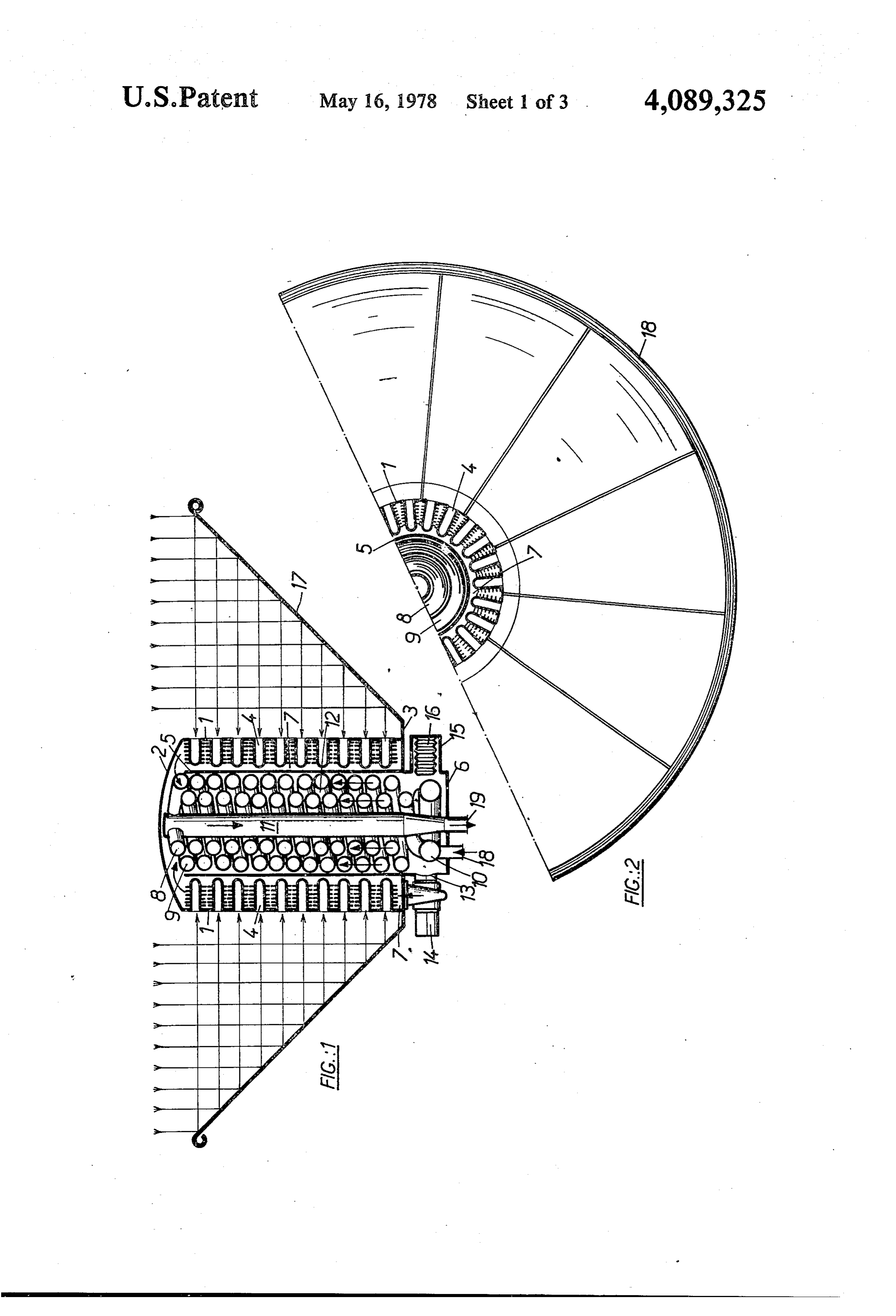
body. A blind cavity may be regarded as a black body On the ring 3 there is mounted a frusto conical reflec if the depth is great enough with respect to its trans tor 17, made of several sectors 18 (FIG. 2). The inner verse size. Consequently, in order to obtain a maximum wall of this reflector is made bright so as to reflect the absorption of the solar radiation, for every wavelength solar radiations towards the center, i.e. in the direction of this radiation, according to the invention, the surface 15 of the black body cells disposed on the wall of cylinder of the boiler, which is exposed to solar radiation com sleeve 1.
prises a plurality of cavities or cells forming black bod The boiler operates in the following way: ies, these cavities being suitably formed by blind cylin The solar radiations are taken by the reflector 17 and der tubes, made of a good heat conveying material, the reflected towards cylinder sleeve 1 where the black depth of which is at least two and half its diameter. body cells are disposed. The radiation penetrates in the Various objects, features and attendant advantages of space of the cells where it is trapped, because after the present invention will be more fully appreciated as repeted reflections, it is dissipated into heat. This heat the same becomes better understood from the following warms the inside wall of the tubes constituting the cells, detailed description of the present invention when con 25 and through conductivity, heat is transfered outside to sidered in connection with the accompanying drawings, the ribs which are lying in the heat conveying fluid. in which: Through forced convection, the heat is taken by the FIG. 1 is an axial section view of a first embodiment liquid and transferred to the tubes of both coils 8 and 9. of the invention; This heat is transferred by convection to the second FIG. 2 is a corresponding half plan view with part in 30 fluid circulating in these coils. The cold liquid enters section; through piping 18 in the collector 10 which is con FIG. 3 is a perspective view of an other embodiment; nected to these two coils. The superheated or vaporized FIG. 4 is an axial section view corresponding to FIG. liquid leaves finally the boiler through piping 19. 3; This type of solar boiler can be used for relatively law FIG. 5 is an axial section view of an other embodi 35 thermal power, for example, for a heating or air condi ment; tionning installation, or even for producing steam nec FIG. 6 is a cross-sectional view corresponding to essary for feeding low power motors.
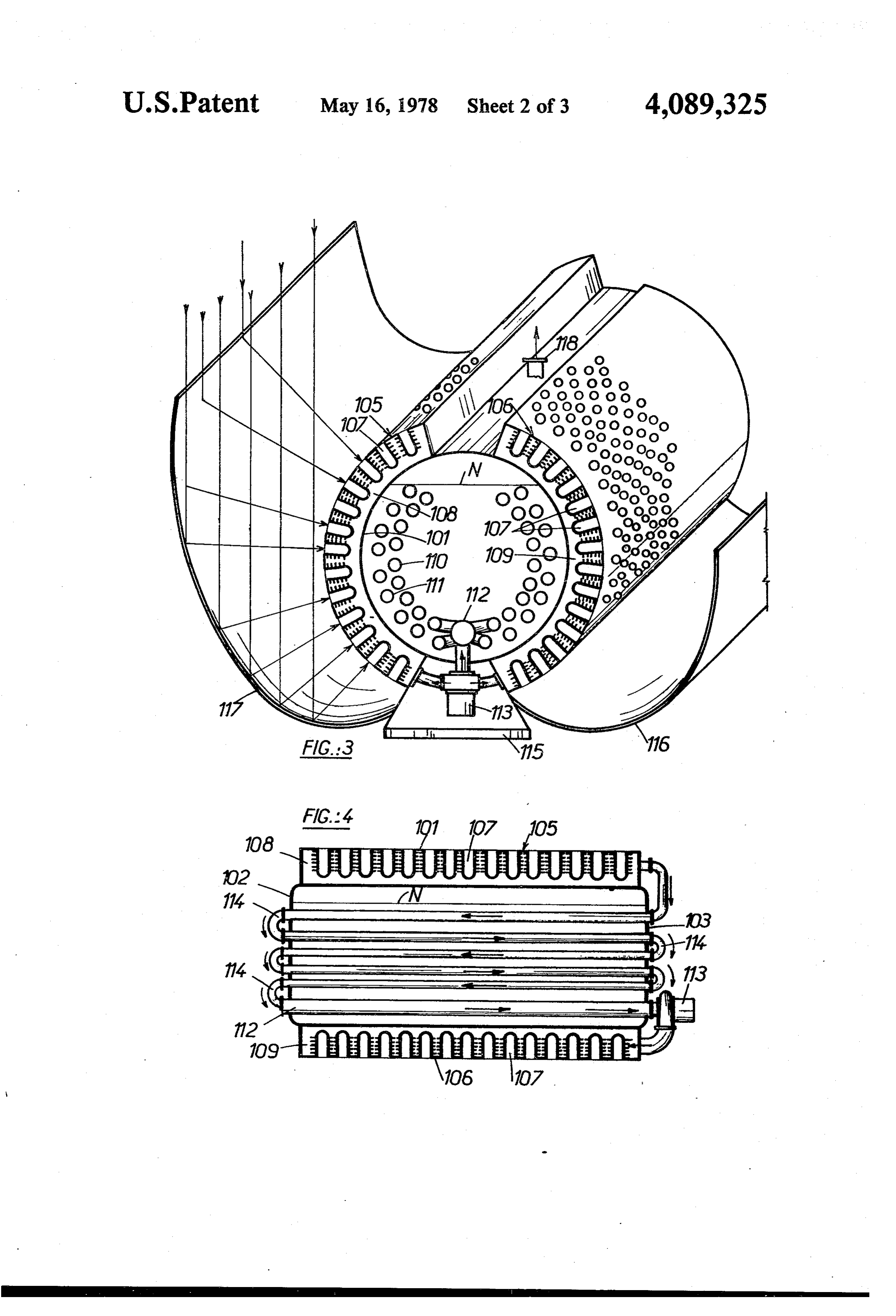
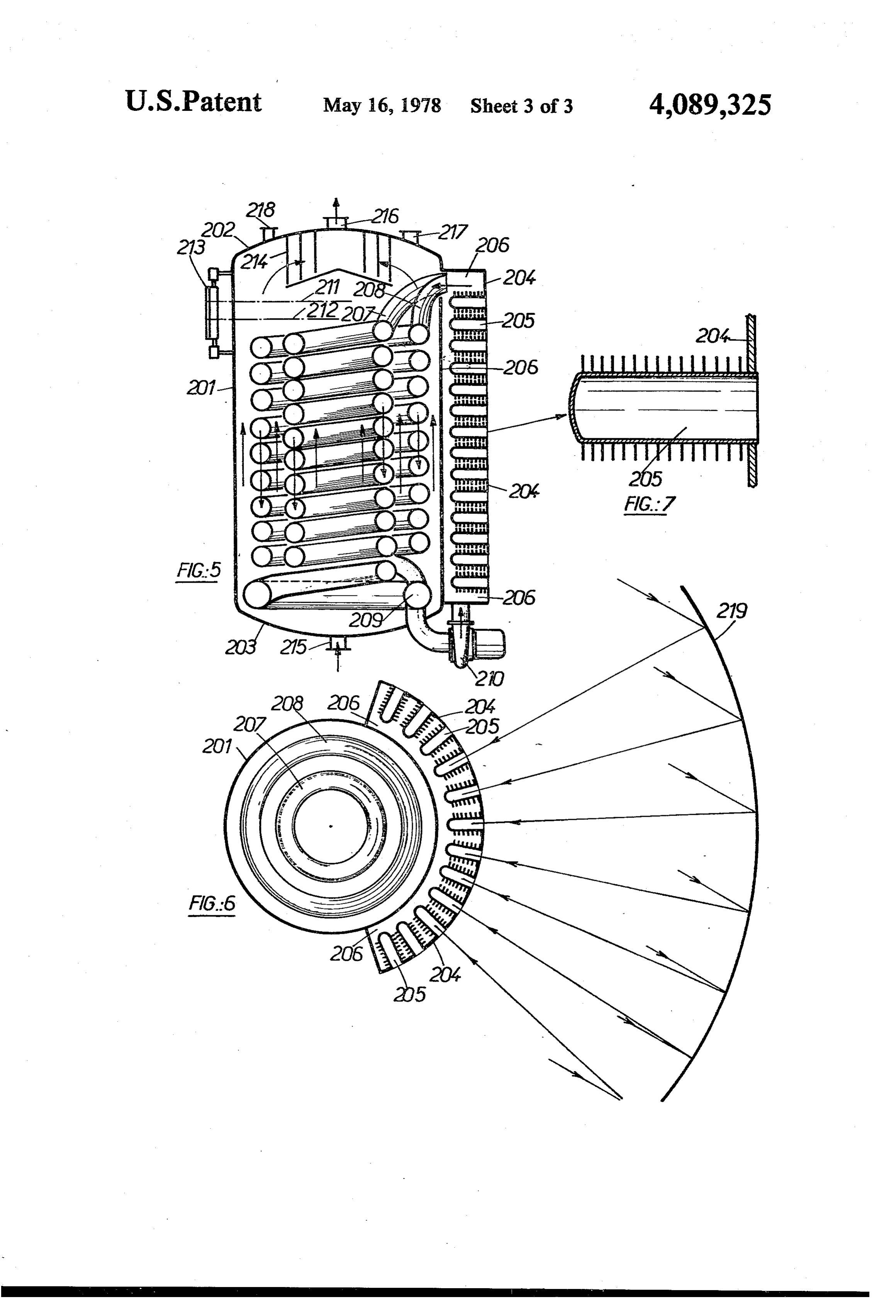
FIG. 5; and In the case of heavy thermal power, an other embodi FIG. 7 is a detailed section view of a cell used as a ment of solar boiler can be used, the principle of opera black body. tion of which is identical, but is different in the con In the embodiment shown on FIGS. 1 and 2, the struction technology.
boiler comprises a sleeve 1, closed at the upper end part Such an embodiment is shown on FIGS. 3 and 4. It by a curved head 2, and at the lower end by an annular comprises an horizontal cylinder tank constituted by a plate or ring 3. Extending on the whole outer wall of sleeve 101 (FIG. 3) closed by two bulging sides 102 and this sleeve, are provided a plurality of cylinder cells 4, 45 103 (FIG. 4). The diameter and length of the sleeve are the length of which is at least two and half greater than choosen according to the power of the boiler. the internal diameter. These cells are formed from por Outside of the sleeve and with the same axis, two tions of an externally ribbed tube of small diameter, the sleeve sectors 105 and 106 are welded, and in which are internal end of which is closed, and the outer end is mounted many cells 107 formed by blind tubes of small welded to the edge of apertures provided in the wall of 50 diameter fitted with ribs. The inner closed space of sleeve 1. These cells form the cavities of black bodies these tubes constitute the black bodies. which absorb solar radiations and produce heat from it. Between the sleeve of the boiler's body and the sec Inside of sleeve 1, a second sleeve 5 is disposed with tors 105,106 are provided two annular spaces 108 and its upper end open and with its lower end closed by a 109 in which the black body cells are projecting. plane plate 6, projecting radially outwardly under the 55 Inside the boiler's body, there is mounted two rows of ring 3. Between sleeve 1 and sleeve 5there is an annular horizontal tubes 110 and 111, the ends of which pass space 7 in which are disposed the externally ribbed through two curved plates 102 and 103. In the lower tubes 4 acting as black body cells. part is placed a collector 112 which connects the two In sleeve 5there are provided two coaxial coils 8 and tubular rows, and outside of this collector is mounted a 9, made of small diameter pipes. These coils are con circulating pump 113 (FIG. 4). The discharge of the nected by their lower ends to a common collector 10 pump is connected to both spaces 108 and 109 where and by their upper ends to a central tube 11. the black body cells are housed. The tubes of rows 110 Coils 8 and 9 are housed in an annular space 12 pro and 111 are series connected by means of return bends vided between inner wall of sleeve 5 and central tube 114 and the upper part of these tubes is connected to 11. This annular space communicates with other annu 65 both annular spaces 108 and 109 (FIG. 4). lar space 7 by means of an opening 13 on which is Inside the two rows and two spaces 108 and 109, mounted the intake of a circulating pump 14, the deliv circulates the heat conveying fluid by means of pump ery of which is connected to annular space 7. 113.
Page 6scan →
The boiler's body is filled up with secondary fluid up Outside, at a distance, is placed the reflector 219 to level N. On the frame 115 are mounted two reflectors which reflects back the solar radiation to the boiler. 116 and 117 of cylindro parabolic form, the inner sur The just described solar boiler operates in the follow face of which is made bright so as to reflect the solar 5 ingReflector way:
219 concentrates solar radiation upon ac radiation received on the cells of the black bodies.
The above described solar boiler operates in the fol tive surface 204 of the boiler, where the black body cells are placed. The cells generate heat which is transmitted lowing way:
The solar radiation is reflected by the two reflectors through forced convection to the heat conveying fluid, which circulates between the cells and also in the two 116 and 117 towards cells 107 where it is trapped and 10 coils 207 and 208 placed in the body of the boiler. The transformed into heat.
Through conductivity, the heat is transferred to the fluid circulation is accelerated by pump 20. ribs of the tubes of these cells, then, through forced received heatforced
Through convection, the coils transfer this to secondary fluid which is placed in the convection of the heat conveying fluid which circulates body of the boiler. This fluid vaporizes, and through around these cells, heat is transferred to tubular rows 15 separator 214 and piping 216, that steam is lead to utili 110 and 111. Afterwards, through convection, this heat zation, i.e. towards a turboalternator. is transferred finally to the second fluid which is inside This boiler system brings the advantage of allowing the body of the boiler. the use of independant reflectors, permitting very high This fluid vaporizes and the steam going out in piping radiation concentrations and so obtain a greater steam 118 (FIG. 3) can be used for moving a turbo-alternator. 20 output to a higher temperature. With this solar boiler, it The advantage of this system of solar boiler is the is possible to build actually helio-electric generation possibility of using cylindro-parabolic reflectors allow station of high power with high efficiency, if complex ing a high degree of radiation concentration of about 20 cycles are applied, with special thermal fluid of low to 30 to be obtained. With this radiation concentration, vapour pressure.
it is possible to produce steam at a temperature of 300 to 25 Although only preferred embodiments are specifi 400 C, and so to realize a complex cycle, the efficiency cally illustrated and described herein, it will be appreci of which may reach about 35 to 40% if special thermo ated that many modifications and variations of the pres dynamic fluids are used. ent invention are possible in light of the above teachings When it is necessary to get a higher thermal power and within the purview of the appended claims without production, from solar radiation, it is possible according 30 departing from the spirit and intended scope of the to the invention, to use a further different embodiment invention.
of a solar boiler, of which the radiation concentration I claim:
system is mounted independantly of the boiler. The 1. A solar boiler comprising in combination: reflector is placed at a greater distance, and covering a a curved surface provided with a plurality of adjacent greater surface, so as to have a more important concen 35 cavities formed each with a blind tube, the length tration factor, and consequently a higher energy density of which is at least two and halftimes its diameter, per surface unit. Such a boiler can be used principally said tubes being normal to the said surface and for producing high pressure steam in view of feeding a located on the concave side of it; high power turboalternator. a reflector adapted to reflect solar rays towards said The boiler comprises a cylindrical sleeve 201 (FIG. 5) surface, and into said cavities; vertically disposed and closed at both ends by two a wall substantially parallel to said surface enclosing a curved bottoms 202 and 203. Along the periphery of region and defining with said surface a space in this sleeve, there is placed, at a distance and only on a which said tubes extend; sector, a second sleeve 204 (FIG. 6). On the wall of this 45 means for subdividing said region into two adjacent sleeve, there are a multiplicity of cells 205 acting as parts one of which communicates with said space black bodies.
and the other of which is separated from it, means for circulating a first heat conveying fluid through
Between this sleeve 204 and sleeve 2011, there is pro the said space and said one part of said region, and vided an annular space 206 in which are housed the rib means for circulating a second fluid through said fitted tubes 205 of the black body cells. This space is 50 other part whereby said second fluid can be heated connected at its upper part to two piping coils 207 and by heat exchange with said first fluid. 208, and at its lower part to a collecter 209 and a circu 2. A solar boiler as claimed in claim wherein said lating pump 210. tubes are fitted each with a series of ribs on their sur The two coils 207 and 208 are placed inside the sleeve faces located in said space, whereby their heat transfer 201. Inside the tubes of these coils, and inside the annu 55 is increased.
lar space 206, a heat conveying fluid circulates under 3. A solar boiler comprising in combination a hollow the action of pump 210. cylinder, a second hollow cylinder defining with said The boiler is filled up with a second fluid up to a level first cylinder, an annular space, means defining a plural between lines 211 and 212, and as can be observed on ity of closely spaced blind tubes mounted on said first gauge 113. cylinder and extending radially into said annular space, In the upper part, there is a vapor separating device a reflector adapted to reflect solar rays towards said 214. surface and into said tubes, heat exchange means subdi The feeding of the boiler with secondary fluid is viding the interior of said second cylinder into two made in the lower part through piping 215, and the regions, one in communication with said annular region steam is going out through piping 216. Control devices 65 and one isolated fromk it. : and safety valves are placed on piping 27 and 218.
Provenance
- Collection
- Patents citing this work
- Pages
- 6
- Method
- pdftotext (the PDF's own text layer) + pdftoppm 300dpi page scans
- Patent office record
- patents.google.com →
- Source
- Google Patents citing-documents table
- Assignee
- Entreprise Industrielle De Chaudronnerie
- Published
- 1978-05-16
- Transcribed from
- patentimages.storage.googleapis.com →