

patent · US4049195A
Solar heated building structure
20 September 1977
Text
Page 1scan →
United States Patent (19)
Rugenstein
(54). solar heated building structure
76 Inventor: Robert W. Rugenstein, Rte. 2, Box
51) Int. C. ................................................. F24, 3/02 52 U.S.C. .................................... 237/1 A; 126/270;
2,213,894 9/1940 Barry .................................... 26/27 2,680,565 6/1954 LSf ....... - -- - - - ---- 126/27 3,841,302 10/1974 Fallbel ................................... 126/271 3,902,474 9/1975 Pyle ..... ... 237/1 A 3,949,732 4/1976 Reines ................................. 2377. A 3,955,555 5/1976 Bostrom ............................... 126/270 4,020,989 5/1977 Kautz ................................., 237/1 A Primary Examiner-John J. Camby
Assistant Examiner-Henry C. Yuen
Attorney, Agent, or Firm-Luke J. Wilburn, Jr.;
Wellington M. Manning, Jr.
A solar-heated building structure comprising an exte rior shell including a generally semi-spherical roof sec tion comprising a plurality of light-transmitting panes of material providing a air and water-tight exterior surface therefor, horizontal floor means dividing the shell into a heat-insulated living compartment, and an attic com partment extending between the living compartment and the roof section to form a solar heat collector. Air in the attic compartment is heated by absorbed energy from sunlight passing through the light-transmitting panes of the roof section. Means are provided for circu lating air into and out of the attic compartment to heat the same, and for circulating the thus heated air through the living compartment to maintain the living compart ment at a desired temperature. Means are also provided in the shell for storing heat energy from the heated air for use to heat the living compartment when sunlight energy is unavailable.
17 Claims, 2 Drawing Figures
Drawings
Page 2drawing sheetscan →
Page 3drawing sheetscan →
Page 4scan →
SOLAR HEATED BUILDING STRUCTURE solar collector panel receives sunlight radiation normal to its collector surface only for a very short period of the day, i.e., during solar noon. Thus, a large amount of
The present invention relates to a solar-heated build morning and afternoon sunlight is not effectively re ing structure and, more particularly, to a building struc 5 ceived by the collector panels.
ture of unique construction containing a solar heat col Although passive type solar collector panels are less lection compartment which with associated conduits, expensive than the active, tracking type solar collectors, and circulating and storage means, provides economical they also are considerably expensive to construct and to and effective heating and/or cooling of the building for install in conventional roofing systems. The number, year round comfort. 10 arrangement, and location of the absorber plates in the Because of the increasing expense and potential un panels make the panels themselves quite expensive, and availability of fossil fuels, such as oil, gas, and other the necessary auxiliary conduits and piping required to petroleum products, the sun is becoming an increasingly transport the heat transfer medium to and from the important source of energy for use by man. Major ef individual panels and into the habitable portions of the forts, both in the national and private sectors, are being 15 building greatly add to the cost of the construction of made to develop suitable equipment for effectively col the structure to be heated and/or cooled. Also, if liquid, lecting and utilizing solar energy as a replacement for such conventional fuels in energy applications, such as in the leaksas water, is employed as the heat transfer medium, can develop in the system and anti-freeze solutions heating and cooling of residential homes, office build must be employed to prevent freezing of the liquid in ings, and in industrial installations. 20 the collector during low temperature periods, such as at A major problem connected with the effective uses of night, when sunlight is not available to heat the collec solar energy by man resides in developing an economi tor.
cal and effective means for collecting, storing and sub majorIfexpense air is employed as the heat transfer medium, a is involved in providing necessary duct sequently utilizing the solar energy as needed. The total ing for transmission amount of solar energy, or radiation, which may be 25 collector units. One of the air to and from the individual such solar-heated and cooled build available to a solar collector unit is defined as "solar ing structure employing collector panels is described in insolation' and comprises the total of the direct, diffuse, U.S. Pat. No. 2,680,565.
and reflected radiation available to the collector. Since Thus, it can be seen that solar heating systems utiliz direct radiation on a clear sunny day accounts for about ing such passive collector panels are not only expensive 88 to 95% of the insolation, it is essential to maintain the 30 initial construction, but also effectively receive only sunlight-receiving surface of the solar collector normal ainsmall part of the expected insolation due to the posi to the direct rays of the sunlight for maximum effi tion of the sun in the early and late portions of the day. ciency of the collector. To accomplish this, active, or It is therefore an object of the present invention to moving, solar collector units have been developed provide a building structure having improved passive which operate to track the movement of the sun and/or 35 solar collection means in the roof portion of the struc condense the sun's rays into a single collection point. ture which overcomes, to a great extent, many of the However, because of the complexity and expense in aforementioned problems of the prior art.
volved in the construction and operation of such active It is a more specific object of the present invention to solar collector systems, they are quite impractical for provide use in residential and small building heating and cooling 40 collectiona means building structure having improved solar systems. Therefore, in the solar heating and cooling of tially all available which effectively captures substan small building and residences, less expensive passive the daylight hours of the day. throughout most of solar insolation collector units, or panels, have been employed. It is another specific object to provide a building Typically, conventional passive, or non-moving, col structure lector panels consist of an insulated box or housing 45 which doeshaving improved solar collection means having an outer cover plate of light-transmitting mate building structure to locatea precise not require the orientation of the solar collection means rial, such as glass, reinforced plastic, or the like, and an on a directly south exposure.
interior compartment beneath the cover plate which It is another specific object to provide a building contains heat absorbing elements, or plates, of dark, or structure having improved solar collection means pro black-painted materials, such as copper, steel, or alumi 50 viding the roof component of the structure and wherein num. Air or liquid is passed through the interior com the heat transfer compartment of the solar collection partment across the absorber plates and serves as a heat means is of extremely large capacity to enable collec transfer medium which is distributed by suitable piping tion and storage of large volumes of heated air for use in or ducting to the habitable areas of the building to be the heating and/or cooling of the building. heated. To obtain maximum direct radiation from the 55 It is another specific object to provide a building sun, a number of these passive collector panels or boxes structure having an efficient and extremely economical are positioned generally in the roof structure of the solar heating and/or cooling system which eliminates a building and must be directly aligned with true south (in large portion of the heat exchange medium piping and the Northern hemisphere). It is also desirable for maxi ducting conduits employed in passive solar heat collec mum effectiveness of collection to maintain an angle of 60 tor systems of the prior art.
the plates, and thus the roofline of the building, such It is a further object to provide a building structure that the panels receive the direct rays of sunlight normal having means for efficiently and economically collect to their receiving surfaces at solar noon. However, ing available sunlight energy, and for storing excess of because of building site restrictions and limitations, it is such energy collected during peak periods for subse often not possible to provide a true south orientation of 65 quent use when sunlight is not available for heating the collector panels in the building structure nor to and/or cooling of the building.
obtain the optimum roofline angle. Because of the travel It is still a further object of the invention to provide a of the sun across the sky, even a true south-oriented building structure having solar heat-collecting capabili
Page 5scan →
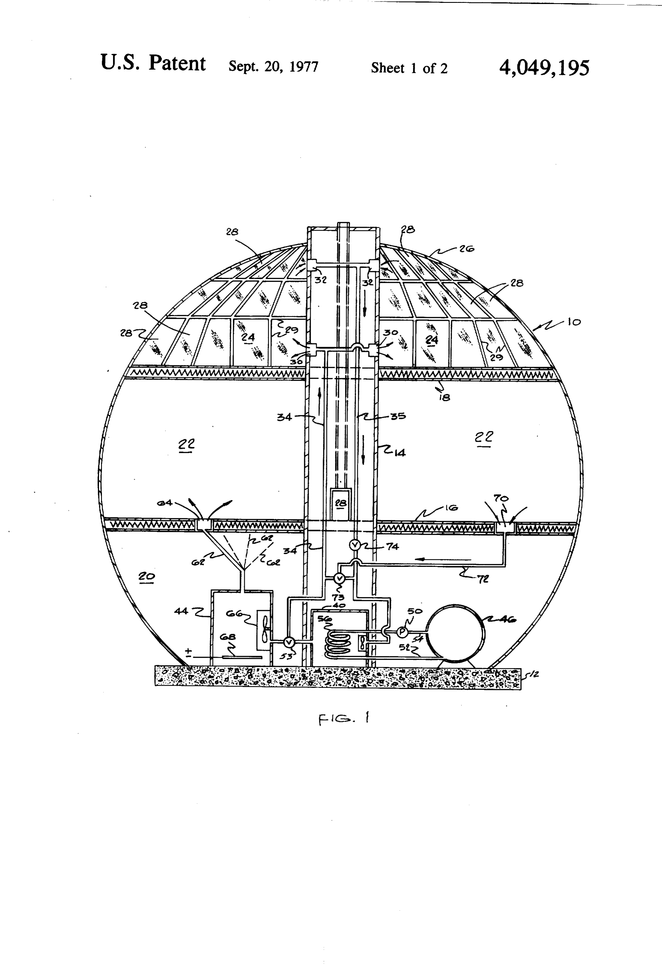
3 tionship by suitable metal or wooden framing 29 to form ties in which collected energy may be readily utilized to the semi-spherical roof section of the building shell 10. provide potable hot water for domestic use, if desired.
In its broad aspects, the present invention comprises a andThefloorentire attic compartment 24 between the roof 26 18 thus serves as a large solar heat collector unique solar-heated building structure comprising an 5 which receives sunlight passing through the semi exterior shell having a generally semi-spherical roof spherical roof section section which permits passage of sunlight into the shell, absorbing capability ofpanes the 28. To increase the heat attic compartment, the sur horizontal floor means within the shell dividing the face of floor 18 as well as the exterior walls of the col interior of the shell into a living compartment and large umn 14 may be painted with black paint, or black poly attic compartment between the living compartment and O ethylene sheets may be placed throughout the floor of roof section for storage of air heated by sunlight passing the attic compartment. The large volume of air con through the roof, and means extending through the tained in the attic compartment is thus heated to a high floor means, and into and out of the attic compartment temperature by the transfer of the heat from the heat for the passage of heated air for heating and/or cooling of the living compartment of the building structure. 15 absorbing surfaces of the floor 18 and column walls. Extending through the wall of central column 14
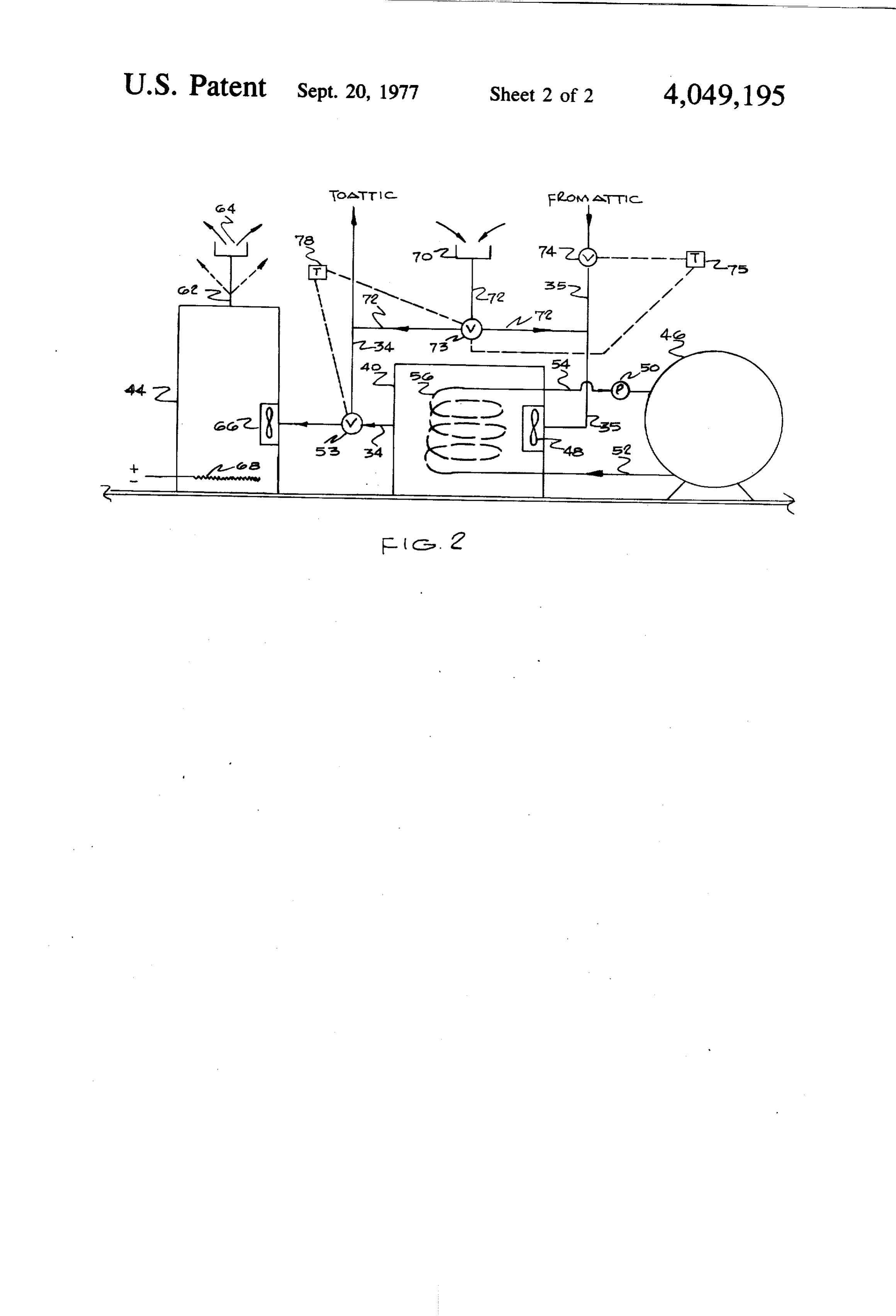
The above as well as other objects of the present adjacent floor 18 of the attic compartment are one or invention will become more apparent, and the invention more openings 30 for the passage of air to be heated into will be better understood, from the following detailed the attic compartment, while one or more openings 32 description of a preferred embodiment of the present in the wall of the column adjacent the upper roof of the invention, when read in connection with the accompa 20 attic provide for the passage of heated air out of the nying drawings, in which: attic. Openings 30 and 32 respectively communicate, by FIG. 1 is a schematic sectional elevation view of a way of suitable conduits, such as insulated ducts or solar heated building structure embodying features of pipes 34 and 35, with heat-distributing components in the present invention, and showing the arrangement the lower utilities level 20 of the shell. Incoming cooler and location of the principal components of the solar 25 air passing through the openings 30 adjacent the floor of heating system of the structure; and the attic rises as it is heated and passes out of the attic FIG. 2 is a schematic diagram illustrating, in more compartment through the openings 32 in the upper detail, the interconnection of the components of the portion of the attic.
solar heating system of the building structure of FIG. 1. Located in the lower utilities level 20 of the building Referring more specifically to the drawings, the solar 30 shell are means for collecting solar heat energy and heated building structure of the present invention, as circulating heated air throughout the living compart seen in FIG. 1, comprises a generally spherical outer ment of the shell. As shown, the principal components shell 10 supportably mounted on a building site by a in the lower level comprise a heat exchange unit 40, a suitable foundation or support base, such as a concrete furnace 44, and one or more hot water storage tanks 46. slab 12, of requisite thickness. Supported on the founda 35 As illustrated schematically in FIG, 2, the air inlet and tion and extending vertically upwardly through the outlet sides of the heat exchange unit 40 are connected, center of shell 10 is a hollow masonary column 14 respectively, to air ducts 35 and 34 which extend up which serves as a central support for the exterior walls wardly through the central column of the shell and of the shell and horizontal floors 16, 18 of the structure, communicate with the interior of the attic solar heating Support column 14 also serves as a central passageway compartment, as previously described. Fan means 48 for air and/or liquids into and out of the attic solar heat provided adjacent the air inlet side of heat exchange compartment and to the heating and/or cooling system unit 40 circulates heated air from the attic heating com components of the building, as will be explained. partment through the exchanger and back into the As shown, the spherical shell 10 of the building is lower portion of the attic. Water from water storage divided by horizontal, heat-insulated floors 16 and 18 45 tank 46 is continuously or intermittently circulated by into a lower utilities level 20, central main living com pump 50 and conduits 52 and 54 through a water coil 56 partment 22, and an upper attic compartment 24 be of the exchanger 40 for heating the water in the storage neath the roof 26 of the shell. Central support column energy tank. This heated water thus serves to store solar heat 14 may also serve as a passageway for a chimney flue for subsequent use in heating of the living com from a conventional fireplace 28 located in the main for directlyofheating 50 partment the building when sunlight is not available the air, as will be explained herein living compartment 22 of the building.
As seen in FIG. 1, the roof section 26 of shell 10 is of after.
generally semi-spherical shape and comprises a plurality The air outlet side of the heat exchange unit is alterna of light-transmitting panes or sheets 28 which permit tively connected by a two-position, thermostatically passage of sunlight into the attic compartment 24 of the 55 controlled valve 53 and conduit to the interior of the shell. The individual light-transmitting panes 28 which furnace 44, which is provided with a fan 66 to supply form the outer semi-spherical roof section of the shell heatedoneairofbywhich, suitable outlet air ducts 62 to heat regis are preferably comprised of transparent sheets of mate ters, 64, is shown, located in the various rial having excellent thermal insulation properties. Ex rooms of the living compartment of the shell. Thus cellent results have been obtained in the use of HCH-76 60 furnace 44, fan 66, and air ducts 62 serve as air distribu glazing panes manufactured by HCHAssociates, Inc. of tion means to direct heated air from the heat exchanger Robbinsville, N.J. Such glazing panes are composed of 40 into the living compartment of the shell. Furnace 44 rigid polyvinyl chloride sheets having wire mesh rein iscalalso provided with heating means, such as an electri coil 68, which may be utilized as an auxiliary source forcement embedded therein. Such panes have a ther 65 of energy to heat the living compartment of the shell mal insulator K-factor of 1.3, or approximately 20 times greater than that of plain glass of equivalent thickness. when sufficient solar heat energy is not available for this purpose. To return air from the living compartment to
The panes conveniently may be cut into the desired the heat exchanger or to the attic compartment for geometric shapes and supported in air-tight, sealed rela 6 reheating, an air return outlet 70 in the living compart If desired, auxiliary equipment, such as a clothes ment is connected by a suitable air return conduit 72, dryer, may be connected into the heating system and and a thermostatically controlled, three-position valve hot air supplied for drying clothes by way of a conduit 73, which is operable to selectively direct return air line and a manually operated valve and conduit con from the living compartment to the heat exchanger (by necting the dryer to the heat exchanger 40. way of conduit 35) or to the attic by way of return duct Although two thermostats and three thermostatically 34. The position of valve 73 is controlled by thermostats controlled valves have been shown to illustrate one located in the attic compartment and living compart manner for directing heated air in the various modes of ment, as will be explained. Air duct 35 from the attic operation of the heating system, it is obvious that the compartment is also provided with a thermostatically 10 number of valves employed and their specific locations controlled valve 74 and its operation will be hereinafter in the airflow lines may vary, depending on the capabil described. ity and type of valves utilized. As best illustrated by the schematic diagram of FIG. If it is desired to employ the solar heat energy col 2, the heat distribution system of the solar heated build lected in the attic solar collector compartment for cool ing structure is provided with several modes of opera 15 ing the living compartment of the shell, a suitable air tion, depending upon the available solar energy for conditioning unit would be provided in the utilities heating and the heating requirements of the living com level of the shell and connected in suitable manner to partment of the building shell. In a first mode of opera receive heat energy from thhe hot water from heat tion, when the temperature of the air in the attic solar 20 exchanger 40 to operate the air conditioning unit, and heat compartment rises above a preselected value, e.g., the manner of connection of the air conditioning unit 80'F., and heated air is not required to heat the living thereto is believed to be well within the skill of those compartment 22, air control valve 74 is automatically familiar with the art.
opened and valve 73 closed by means of a thermostat 75 If additional heat energy is required above that which in the attic, and heated air from the upper portion of the 25 may be provided by the heated air system described, a attic compartment is continuously drawn through con series of water pipes may be provided on the floor of the duit 35 into the inlet side of the heat exchanger 40 by fan attic could compartment, and heated water from this system be similarly conveyed through the central col 48. Water circulating through the coils of the heat ex changer from water storage tank 46 is thus heated by umn of the shell to the heat exchanger and air condition the air and stored in the tank for use to heat the living ing unit in a manner obvious to one skilled in the art. compartment during periods when sufficient sunlight is 30 Since it is unnecessary to provide an anti-freeze solu tion in the water in storage tank 46 to prevent it from not available for this purpose, as will be explained. Air freezing, leaving the air outlet side of heat exchanger 40 passes by ployed the hot water in the storage tank may be em way of air valve 53 directly through duct 34 back into able piping, not for directly household and domestic use. Suit shown, may be connected to the hot the attic compartment for reheating. 35
In a second mode of operation, whenever the temper water storage tank and directed to faucet outlets in the ature in the living compartment drops below a desired living compartment of the building for this purpose. level, e.g., 72 F., two-position valve 53, which is con tion describedinherein,
Although, the preferred embodiment of the inven the semi-spherical roof section of trolled by a thermostat 78 in the living compartment, is the building shell has been shown and described as automatically positioned to direct all air leaving the exit 40 being comprised of light-transmitting panes substan side of heat exchanger 40 into furnace 44, where it is tially throughout the total surface area of the semi directed by furnace fan 66 through ducts 62 and regis spherical roof section, it should be understood ters 64 to heat the living compartment of the shell. panes may be employed over less than the total that the surface
Correspondingly, valve 73 is automatically positioned area, so long as sufficient heat is generated in the attic to communicate return outlet 70 with attic return duct 45 compartment to provide the requirements for the build 34, and return air from the living compartment passes ing. Thus, for example, in northern climes of the north by outlet 70, conduit 72, valve 73, and duct 34 back into ern hemisphere, a portion of the northernmost exposure the lower area of the attic for reheating. of the roof section of the building structure may well be In a third mode of operation, when the temperature in composed of conventional roofing materials, provided the attic solar heat compartment falls below a desired 50 that the heat absorbing surfaces level, e.g., 80 F., and is thus ineffective for heating the ment are not blocked from contactofbythetheattic compart sunlight rays living compartment of the shell, thermostatically con trolled valve 74 is automatically closed and valve 73 to From prevent optimum efficiency of the solar collector. the foregoing detailed description of preferred positioned to communicate air return outlet 70 with embodiments heat exchanger 40 so that return air from the living 55 that the solar of the present invention, it can be seen heated building structure may be effec compartment is passed directly back into the heat ex tively utilized to provide changer 40 by way of return conduit 72, valve 73, and the living compartment offorthe heating and/or cooling of building, as well as to duct 35 where it is reheated by the circulation of hot provide auxiliary heat energy for operating ancilliary water from hot water storage tank 46 and returned to equipment, such as clothes dryers, provide hot water the living compartment by way of furnace 44. for domestic use, and the like. Because of the unique In a fourth mode of operation, when heat is unavaila arrangement and construction of the panels of light ble both from the attic solar heat compartment and the transmitting material and the semi-spherical shape of hot water supply tank to heat the living area, auxiliary the solar collector in the attic portion of the building, heat coil 68 in furnace 44 is energized and air is continu direct rays of sunlight can be received directly into the ously circulated through the living compartment by 65 attic solar collector throughout the major portion of the ducting 62, and returned to the furnace for reheating by day, regardless of the position of the sun in its path way of outlet 70, air return conduit 72, valve 73, duct across the sky.
34, heat exchanger 40, and valve 53. That which is claimed is:
Page 7scan →
1. A solar-heated building structure comprising an air means with said living compartment for distribution of exterior shell including a generally semi-spherical roof thereinto, and fan means for directing heated air from section, said roof section having exterior light-transmit into said said furnace means through said air duct means ting surface means for admitting passage of sunlight into living compartment. said shell, horizontal floor means within said shell divid 7. A structure as defined in claim 6 wherein said air ing the interior of the shell into a living compartment circulating means further includes second air distribu tion means for selectively connecting said living com and an attic compartment extending between said living partment to said first conduit or to said heat exchanger compartment and said roof section for the storage of air to direct air to be heated by sunlight passing through said exterior compartmentfrom or said living compartment into said attic into said heat exchanger for being surface means of said roof section, conduit means ex O tending through said floor means and into said attic heated thereby.
compartment for the passage of air into said attic com circulating 8. A structure as defined in claim 7 wherein said air partment to be heated therein and for the passage of valve meansmeans in said includes thermostatically controlled second conduit and said second air heated air out of said attic compartment, and means in distribution means for closing said second conduit and said shell communicating with said conduit means for 15 for circulating the heated air through said living compart heatdirecting air from said living compartment into said ment and for returning air from said living compartment liquidexchanger storage for being heated by heated liquid in said means when the temperature in said attic to said conduit means for reintroduction into said attic compartment to be heated therein. compartment falls below a predetermined level. 2. A structure as defined in claim 1 wherein said build 20 9. A structure as defined in claim 7 wherein said air ing structure further includes a support base for said circulatingvalve means means include thermostatically controlled therein for directing heated air from said shell, a central support column for said shell mounted attic compartment through said heat exchanger and on said base and extending vertically through said shell back to said attic compartment when the temperature in to said semi-spherical roof section, said column having a central passageway therethrough; and said conduit 25 said attic compartment is above a preselected tempera means comprising a first conduit extending through said tute. 10. A structure as defined in claim 9 wherein said column passageway from adjacent said support base thermostatically and having outlet means communicating with the lower for directing saidcontrolled valve means includes means heated air from said heat exchanger portion of said attic conmpartment adjacent said hori 30 back to said attic compartment by way of said living zontal floor means for introducing air into said attic compartment compartment for being heated therein, and a second partment fallswhen below the temperature in said living com a predetermined level.
conduit extending through said column passageway 11. A structure as defined in claim 1 wherein said roof from adjacent said support base and having inlet means section exterior surface means comprises a plurality of communicating with the upper position of said attic light transmitting compartment adjacent said roof section for removal of 35 for mounting saidpanes panes of material, and support means in juxtaposed water and air heated air therefrom. tight relationship to form said semi-spherical roof sec 3. A structure as defined in claim 2 wherein said means for circulating heated air through said living tion.
compartment includes means positioned below said panes 12. A structure as defined in claim 11 wherein said living compartment in said shell communicating with comprise polyvinyl chloride sheets having a rela said first and second conduits for circulating heated air tively high thermal insulation factor. from said second conduit into said living compartment sheets have 13. A structure as defined in claim 12 wherein said and for removing air from said living compartment and 20 times greater a thermal insulation factor of approximately returning it to said attic compartment by way of said than plain glass of equivalent thickness. first conduit. 45 14. A structure as defined in claim 1 wherein said 4. A building structure as defined in claim 2 wherein floor means defining the floor of said attic compartment said air circulating means includes a heat exchanger are15.comprised of a dark, heat-absorbing surface. communicating with said first and second conduits, fan supportA base structure as defined in claim 14 including a for said shell, a central support column for means associated with said heat exchanger for directing said shell mounted heated air from said second conduit and attic compart through said shell, on 50 said base and extending vertically ment through said heat exchanger and into said first is supportably attached said and semi-spherical roof section said support column for cen conduit for recirculation to said attic compartment, tral support thereby.
means for circulating a liquid through said heat ex 16. A structure as defined in claim 15 wherein said changer in heat exchange relationship with air passing shell is of substantially spherical shape, and wherein therethrough to heat the liquid, and storage means for said floor collecting the heated liquid from said heat exchanger. means and said shell are centrally supported 5. A structure as defined in claim 4 wherein said air by said support column.
circulating means includes first air distribution means 17. A solar-heated building structure as defined in operatively connected to said heat exchanger for re claim 1 wherein said exterior surface means of said roof ceiving heated air therefrom and for directing the section rigid, comprise a plurality of panes of substantially light-transmitting sheet-like material, and means heated air into said living compartment. supporting said panes in juxtaposed water and air-tight 6. A structure as defined in claim 5 wherein said first air distribution means comprises furnace means having said relation to form substantially the entire surface are of a heated air inlet operatively connected to said heat 65 semi-spherical roof ssection. exchanger, air duct means connecting said furnace
Provenance
- Collection
- Patents citing this work
- Pages
- 7
- Method
- pdftotext (the PDF's own text layer) + pdftoppm 300dpi page scans
- Patent office record
- patents.google.com →
- Source
- Google Patents citing-documents table
- Assignee
- Rugenstein Robert W
- Published
- 1977-09-20
- Transcribed from
- patentimages.storage.googleapis.com →