

patent · US4696284A
Solar heated canteen
29 September 1987
Text
Page 1bibliographic recordscan →
United States Patent (19)
Stowell
54 SOLAR HEATED CANTEEN
Inventor: Dennis E. Stowell, P.O. Box 796,
Parowan, Utah 84761
Related U.S. Application Data (63) Continuation-in-part of Ser. No. 826,802, Feb. 6, 1986, abandoned.
51 Int. Cl“................................................. F24J 3/02 (52) U.S. C. .................................... 126/437; 126/450;
4,239,032 12/1980 Irving ....... ... 126/437 4,299,201 ll/1981 Tsubota............................... 126/440
4,557.251 12/1985 Burkhardt ....................... 126/437 X
Primary Examiner-Larry Jones
Attorney, Agent, or Firm-Norman B. Rainer
A canteen-like apparatus which confines potable water is adapted to heat the water by solar energy. The appa ratus has a water-confining vessel substantially sur rounded by a thermally insulating jacket. The vessel is comprised of an upper panel of spherical curvature convexly directed away from the interior of the vessel, and an opposed lower panel. A flat fresnel lens having a circular perimeter of larger diameter than the diame ter of the transparent panel is attached at its perimeter to the insulating jacket and thereby disposed above the transparent panel to form an air chamber. Rays of sun light pass through the fresnel lens and converge toward and impinge perpendicularly upon the upper panel, thereby producing efficient heating of the water. 7 Claims, 3 Drawing Figures
Drawings
Page 2drawing sheetscan →
Page 3scan →
of said bottom wall as a continuous extension thereof
SOLAR HEATED CANTEEN and having an exterior surface extending between upper and lower extremities and an interior surface comprised
RELATED APPLICATIONS of a lower portion which faces said vessel and abuts said This is a continuation-in-part application based upon boundary edge, and an upper portion disposed above
1986, now abandoned. section which tapers outwardly away from the vessel toward the upper extremity of said exterior surface, and
BACKGROUND OF THE INVENTION (3) a channel which permits close-fitting passage of said This invention concerns a small portable vessel, and 10 spout, more particularly relates to a canteen-like vessel in (c) a circular fresnel lens window of larger diameter which water may be heated by exposure to solar radia than said vessel affixed at its perimeter to the upper tol. extremity of said sidewall and coacting with the jacket Portable solar heating units for campers are well 15 to difine an air chamber above the vessel, said lens being known for cooking food and heating water. They are perpendicularly centered upon the axis of the upper particularly useful where the buildings of a fire for panel and having a focal length coinciding with the heating purposes is impractical. Such units generally center curvature of said upper panel at a site on siad axis rely upon reflective parabolic surfaces which collect below the bottom wall of the jacket, whereby light rays radiation over a relatively large area, and focus the passing through the fresnel lens converge to the area of radiation directly upon the object to be heated. In such 20 the upper panel while passing through the air chamber, instances, use of the apparatus usually requires that the and, impinge perpendicularly upon the upper panel and camper set up several components in stationary juxtapo heat the vessel, and sition, and wait in a fixed location until the heating task (d) a carrying strap forming a substantially closed is accomplished. No storage or accumulation of the 25 loop, a part of which embraces the exterior surface of solar-generated heat is usually contemplated. The re said sidewall.
flectors are usually fragile, or if durably constructed are In preferred embodiments, a dial thermometer is asso expensive and bulky. U.S. Pat. No. 4,557,251 to Burk ciated with the vessel. The vessel may be fabricated of hardt discloses a portable and compact heating device a metal, unbreakable glass polycarbonate or polyacryl which disposes water in verythin layers for quick heat ate in which case, the vessel is preferably a monolithic ing. In the Burkhardt device, the rate of heating is such 30 structure. In certain embodiments, the lower panel of that a period of about one hour is required to raise the the vessel is of rounded contour convexly directed out water to its boiling point for each half centimeter depth wardly from the vessel, and joining with the upper of water.
It is accordingly an object of this invention to provide panel ments, at a circular boundary edge. In other embodi the lower panel of the vessel is flat, and is joined a portable water confining apparatus capable of heating to the upper said confined water by solar radiation to boiling temper configurationpanel by a boundary edge panel of circular perpendicularly disposed between said atures at a rate significantly faster than achievable by upper and lower panels.
prior devices. The rays of light focused from the perimeter of the It is a further object of this invention to provide appa ratus as in the foregoing object having a canteen-like 40 fresnel lens toward the vessel define a conical surface which is preferably tangent to the conical section of the configuration.
It is a still further object of this present invention to interior surface of the sidewall. In certain embodiments the lens may be coated through it, or the window may provide apparatus cable of accumulating heat of solar be comprised of a magnifying lens other than a fresnel origin over a period of time.
It is yet another object of the invention to provide 45 lensto a which concentrates solar rays in a manner similar fresnel lens.
apparatus of the aforesaid nature of rugged, durable consturction which can be economically manufactured. BRIEF DESCRIPTION OF THE DRAWING These objects and other objects and advantages of the invention will be apparent from the following descrip For a fuller understanding of the nature and objects tion. 50 of the invention, reference should be had to the follow ing detailed description taken in connection with the
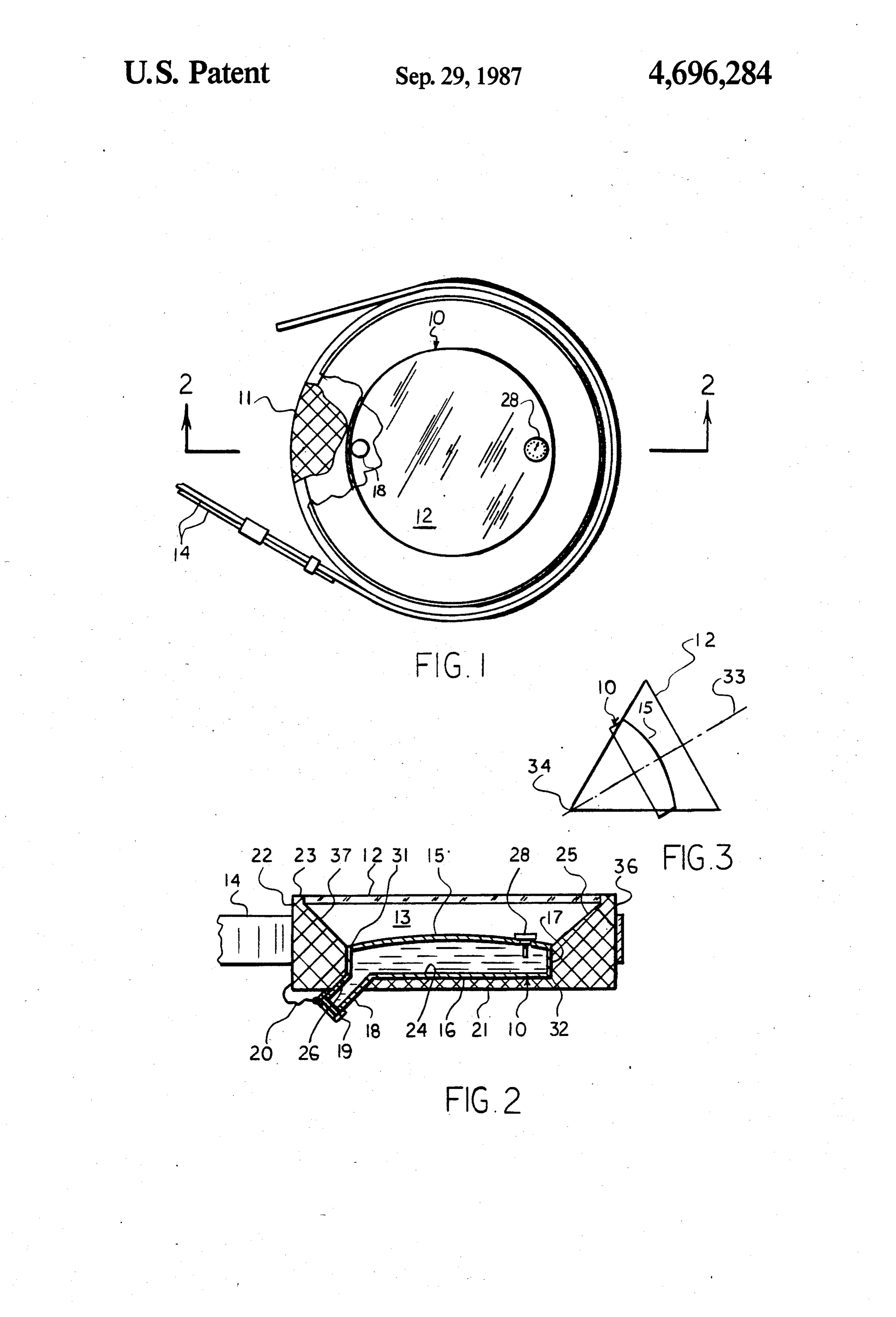
SUMMARY OF THE INVENTION accompanying drawing forming a part of this specifica The above and other beneficial objects and advan tion and in which similar numerals of reference indicate tages are accomplished in accordance with the present corresponding parts in all the figures of the drawing: invention by an apparatus for confining a supply of 55 FIG. 1 is a top elevational view of an embodiment of water and enabling said water to be heated by solar the apparatus of this invention with portions broken radiation, said apparatus comprising: away to reveal interior details. (a) a water-confining vessel having an upper panel of FIG. 2 is a sectional view taken along the line of 2-2 spherically rounded contour convexly directed out of FIG. 1.
wardly from the vessel and centered upon an axis per 60 FIG. 3 is a schematic view showing critical geometri pendicular to said vessel, an opposed lower panel, a cal features of the invention.
boundary edge of circular configuration joining said For convenience in description, the terms "bottom' uppr and lower panels, and a sealable spout communi and "upper", or words of similar import, will have cating with the interior of the vessel, reference to the lower and upper extremities, respec (b) a jacket of self-supporting thermally insulative 65 tively, of the apparatus as shown in FIG. 2. Similarly, material, and comprised of (1) a bottom wall of circular the expressions "inner" and "exterior', or equivalents perimeter adapted to lie in abutment with said lower thereto will have reference to the geometric center of panel, (2) a sidewall rising upwardly from the perimeter said apparatus.
Page 4scan →
DESCRIPTION OF THE PREFERRED The invention is further illustrated by the following
Embodiment
example which is not intended to be limitave thereof.
Example
Referring to the drawing, an embodiment of the ap paratus of this invention is shown comprised of water 5 A canteen-like appartus was utilized having a 14 inch confining vessel 10 emplaced within insulative jacket diameter fresnel of 10 incy focal length adhered at its 11, circular flat fresnel lens window 12 coacting with perimeter to a jacket of foamed polyethylene. The said jacked to define air chamber 13, and carrying strap jacket has a circular sidewall of 4 inch height and 2 inch 14 associated with said jacket. thickness at its lowermost extremity. A flat botton wall Vessel 10, preferably of integral construction, is com O of inch thickness joins the lowermost extremity of the prised of upper panel 15, flat lower surface 16, and sidewall.
boundary panel 17 of circular cylindric configuration A monolithic vessel fabricated of aluminum is posi perpendicularly disposed between upper panel 15 and tioned within the jacket. The vessel has a spherically lower surface 16 and imperviously joined thereto at curved upper panel having a radius of curvature of 83 upper and lower boundary edges 31 and 32, respec 15 inches, a flat lower surface, and boundary panel of cir tively. In alternative embodiments, the vessel may be cular cylindric contour having a height of 178 inch. Said lower surface and boundary panel are in tight-fit fabricated of upper and lower rounded portions joined ting engagement with the jacket. The uppermost point in a single continuous boundary edge, thereby produc ing a vessel configuration without boundary 17. A spout 20 of the upper panel is spaced is inch from the lower surface of the fresnel lens.
18 communicates with the interior of the vessel and is provided with sealing closure means in the form of a ofWhen water, the afore described canteen, filled with a quart is exposed to sunlight in a clear December day threaded cap 19 attached to jacket 11 by a tether line 20. at 58 degrees F. ambinet temperature, the water is A dial thermometer 28 is associated with the vessel so heated to boiling that the dial face is above upper panel 15. The volume 25 Chamber 12 may in 125 minutes. of the vessel may range from about 1 to 4 quarts. Upper than air for improved contain a vacuum or gasses other panel 15 has a spherical curvature convexly directed sun's rays into thermal efficiency of conversion of the energy. Upper panel 15 of said outwardly from the vessel and is disposed about a cen vessel, upon which the solar radiation impinges, may be ter axis 33 perpendicularly disposed to said vessel. The provided with an energy-absorptive coating such as center of curvature of panel 15 is shown in FIG.3 as a 30 black copper oxide or equivalent coatings well known point 34 on the axis below the vessel, which is also the in the art. The fresnel lens may be coated with an anti focal point of fresnel lens 12.
Insulative jacket 11, preferably fabricated of a closed reflective therethrough.
coating to enhance transmission of light
Removable thermal insulative means cell foam of a polymer as polystyrene, polyethylene or may be associated with the outwardly disposed face of polyurethane, is comprised of bottom wall 21 of circu 35 said window panel to retain heat within the canteen lar perimeter, and sidewall 22 rising perpendicularly when sunlight is not entering the window. from said bottom wall to circular uper extremity 23 and Carrying strap 14, preferably of adjustable length, is bounded by interior and exterior surfaces 25 and 36, attached to sidewall 22 in the general manner typical of respectively. a conventional canteen. By virtue of its canteen-like The upwardly directed face 24 of bottom wall 21 is 40 structure, the apparatus may be carried while exposing adapted to lie in gripping abutment with lower panel 16 the window to the sun's rays. For example, the appara of the vessel. The lower portion of interior surface 25 of tus may be mounted in mobile modes such as uon a back sidewall 22 is adapted to lie in gripping abutment with pack, or horse's saddle, a boat, a bicycle, canoe, snow boundary panel 17 of the vessel, whereby the vessel is mobile, or in immobile modes such as upon a tent, tree, securely held in place by the insulative jacket. The or in still other modes typical of outdoor activities. upper portion 37 of interior surface 25 is disposed above While particular examples of the present invention the upper panel of the vessel and tapers outwardly away have been shown and described, it is apparent that from the vessel toward upper extremity 23 of the side changes and modifications may be made therein with wall, thereby constituting a section of a conical surface out departing from the invention in its broadest aspects. taken perpendicularly transverse to the cone axis. A 50 The aim of the appended claims, therefore, is to cover chamber 13, which is bounded by window panel 12, all such changes and modifications as fall within the upper panel 15, and tapered upper portion 37 of the true spirit and scope of the invention. interior surface of the sidewall, is therefore caused to Having thus described my invention, what is claimed have substantially the shape of a transverse section of a S.
cone. A channel 26 in bottom panel 21 permits penetra 55 1. Apparatus for confining a supply of water and tive passage of spout 18. enabling said water to be heated by solar radiation, said Window 12 is a flat fresnel lens of circular perimeter apparatus comprising:
perpendicularly centered upon axis 33 and adhered at its (a) a water-confining vessel having an panel of spheri perimeter in an impervious manner to upper extremity cally rounded contour convexly directed out 23 of sidewall 22. The focal point of the fresnel lens is wardly from the vessel and centered upon an axis chosen to coincide with the radius of curvature of panel perpendicular to said vessel, an opposed lower 15, as shown in FIG. 3. By virtue of such critical char panel, a boundary of circular configuration joining acteristic, all light rays gathered by the lens and concen said upper and lower panels, and a sealable spout trated inwardly toward the vessel strike upper panel 15 communicating with the interior of the vessel, perpendicularly. This minimizes reflection of light from 65 (b) a jacket of self-supporting thermally insulative panel 15, a source of inefficiency of earlier solar collec material, and comprised of (1) a bottom wall of tors. Consequently, a very high percentage of the light circular perimeter adapted to lie in abutment with impinging upon panel 15 heats the vessel. said lower panel, (2) a sidewall rising upwardly 5 from the perimeter of said bottom wall as a contin (d) a carrying strap forming a substantially closed uous extension thereof and having an exterior sur loop, a part of which embraces the exterior surface fact extending between upper and lower extremi of said sidewall.
2. The apparatus of claim 1 wherein a dial thermome ties and an interior surface comprised of a lower 5 ter is associated portion which faces said vessel and abuts said with the vessel. boundary, and an upper portion disposed above the 3. The apparatus of claim 1 wherein said vessel is a upper panel of the vessel and shaped as a conical lows monolithic structure of transparent material which al section which tapers outwardly away from the the water the solar rays to penetrate into the vessel and heat directly.
vessel toward the upper extremity of said exterior 10 4. The apparatus surface and (3) a channel which permits close-fit of said vessel is rounded of claim 1 wherein the lower panel ting passage of said spout, contour convexly directed (c) a circular lens window of larger diameter than panel at a circular boundaryand outwardly from the vessel joining with the upper edge.
siad vessel affixed at its perimeter to the upper extremity of said sidewall and coacting with the 15 of5.saidThe apparatus of claim 1 wherein the lower panel vessel is flat and is joined to the upper panel by jacket to define an air chamber above the vessel, a boundary edge panel of circular cylindric configura said lens being perpendicularly centered upon the tion perpendicularly disposed between said upper and axis of the upper panel and having a focal point lower panels.
coinciding with the center of curvature of said 6. The apparatus of claim 1 wherein rays of light upper panel at a site on said axis below the bottom 20 focused from the perimeter of the lens toward the vessel wall of the jacket, whereby light rays passing deifne a conical surface which is tangent to the conical through the lens converge to the area of the upper section of the interior surface of the sidewall. panel while passing through the air chamber, and 7. The apparatus of claim 1 wherein said window lens impinge perpendicularly upon the upper panel and is a fresnel lens. k 3 k k sk
Provenance
- Collection
- Patents citing this work
- Pages
- 5
- Method
- pdftotext (the PDF's own text layer) + pdftoppm 300dpi page scans
- Patent office record
- patents.google.com →
- Source
- Google Patents citing-documents table
- Assignee
- Stowell Dennis E
- Published
- 1987-09-29
- Transcribed from
- patentimages.storage.googleapis.com →