

patent · US4099516A
Solar energy pick-up
11 July 1978
Text
Page 1bibliographic recordscan →
United States Patent (19)
Caulier
(54). SOLAR ENERGY PICK-UP
76 Inventor: Daniel Pierre Caulier, Route d'Aix, 13122 Ventabren
(Bouches-du-Rhône), France
(30) Foreign Application Priority Data
Apr. 30, 1975 FR France ................................ 75 14247 Int. C.’................................................. F24J 3/02 52 U.S. C. .................................... 126/271; 237/1 A
937,013 10/1909 Severy ................................. 126/271
1,345,758 7/1920. Folsom ................................. 126/271 1,951,403 3/1934 Goddard .............................. 126/271 3,929,122 12/1975 Alkasab ................................ 126/271 3,957,031 5/1976 Winston ............................... 126/270 3,990,430 1 1/1976 Robertson ............................ 126/271 4,003,366 1/1977 Lightfoot ............................. 126/271 401 1,855 3/977 Eshelman ............................. 126/271 Primary Examiner-Kenneth W. Sprague
Attorney, Agent, or Firm-Lewis H. Eslinger
The present invention relates to solar energy pick-ups composed of a fixed cylindrical mirror having an ellip tic transverse section and a heat collector parallel to the generatrices of the cylinder, placed at the bottom of the mirror, in the plane parallel to the large axis of the ellipse in which a heat-carrying fluid circulates.
12 Claims, 9 Drawing Figures
Drawings
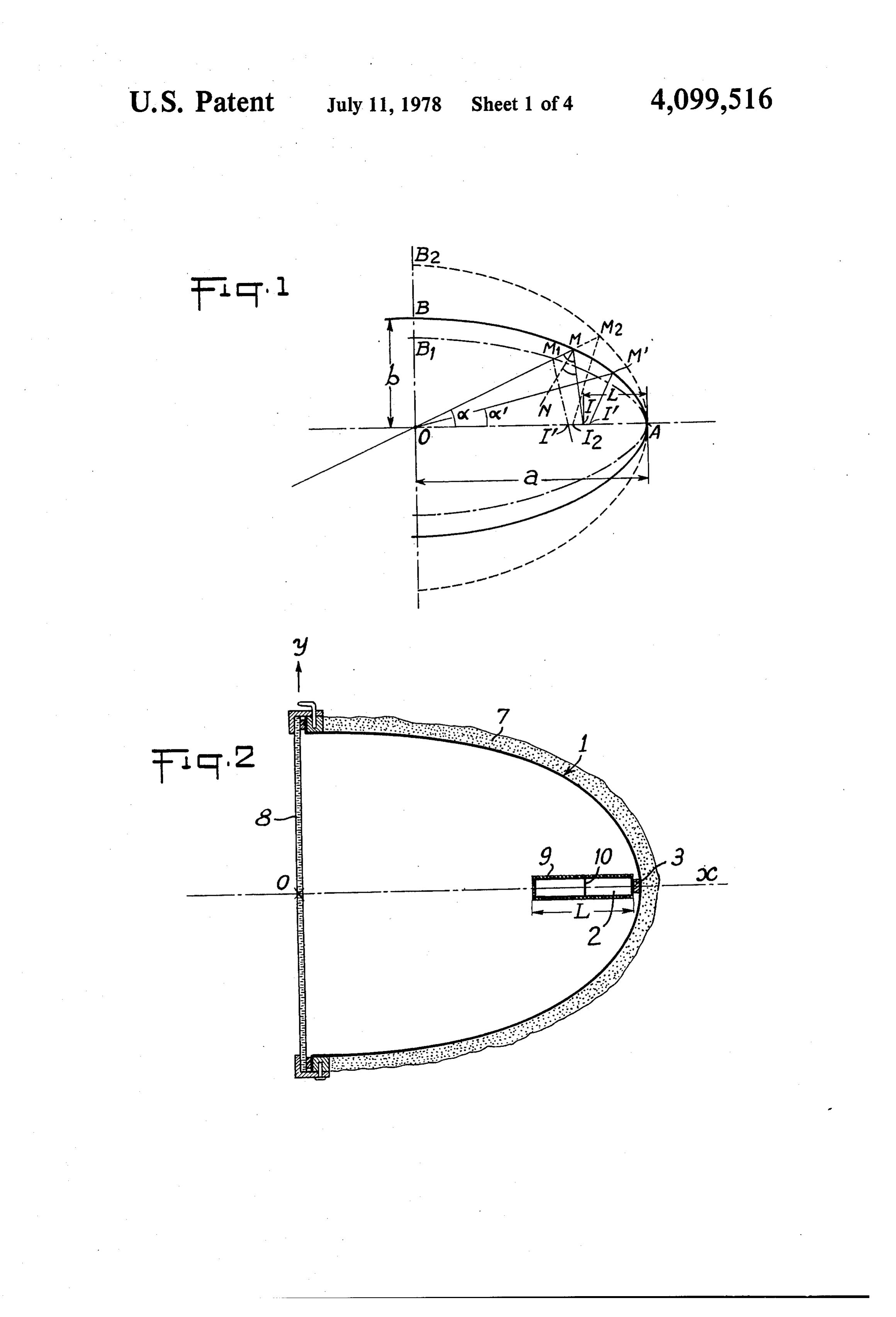
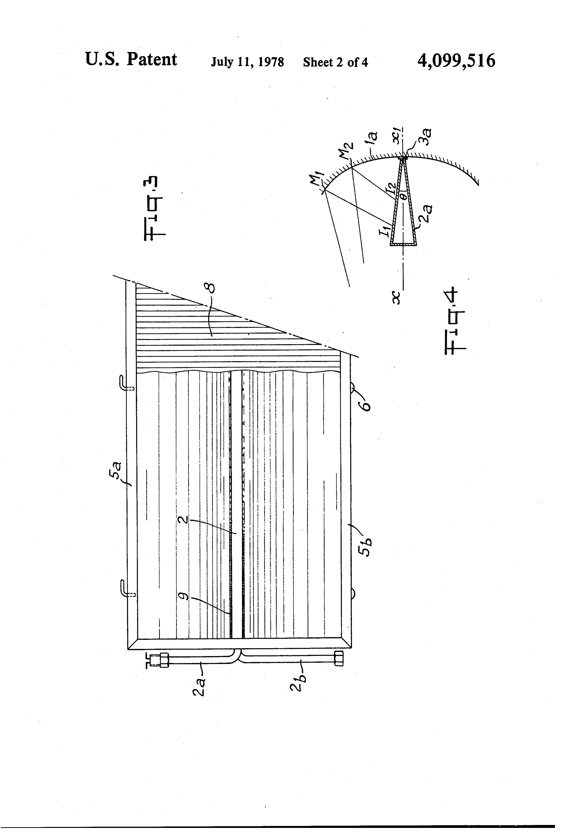
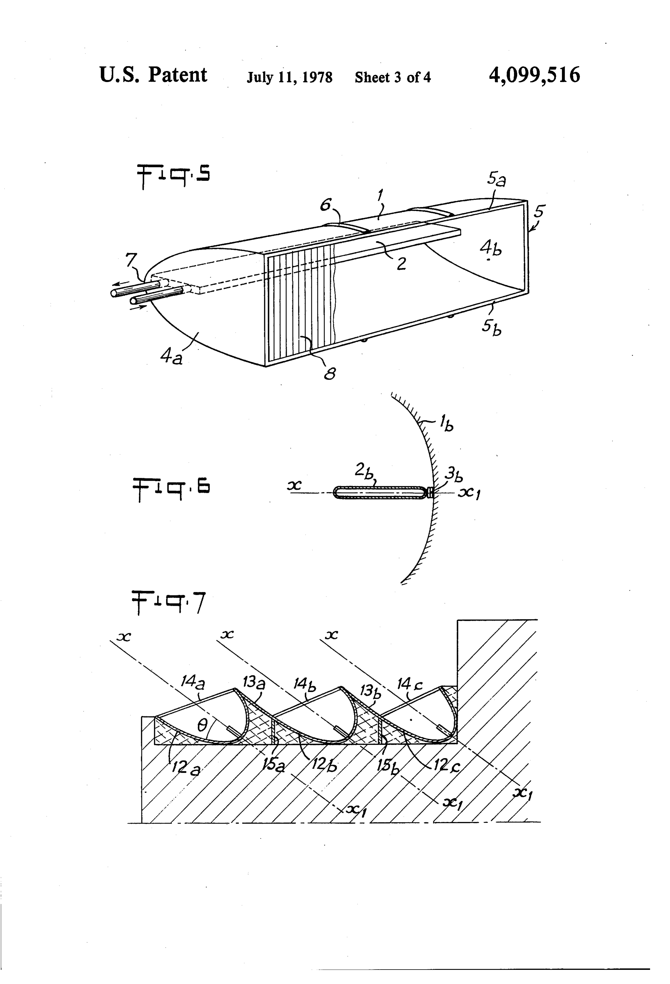
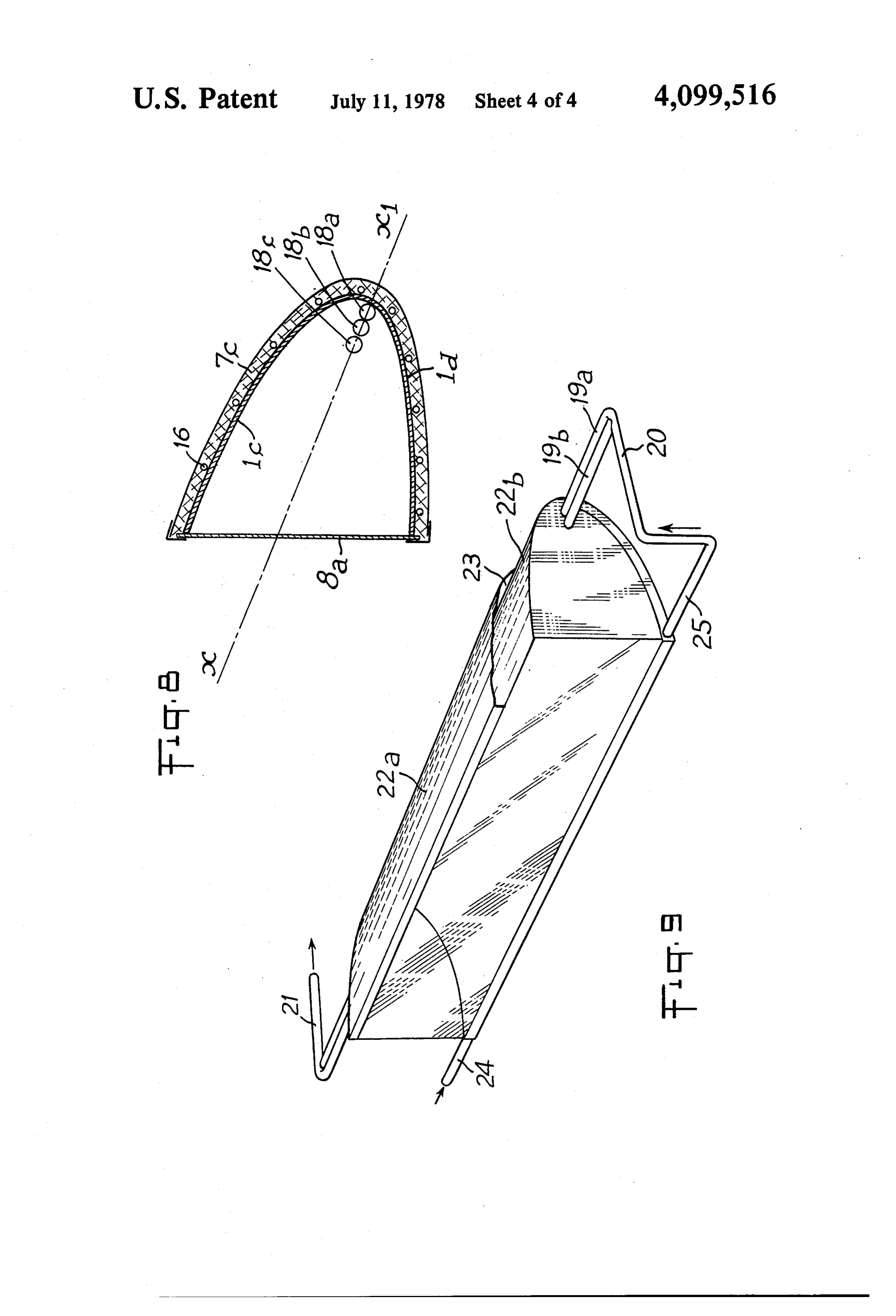
FIG. 9 is a perspective view of another variant em The optimum eccentricity increases when the angle a bodiment. decreases.
Page 2drawing sheetscan →
Page 3drawing sheetscan →
Page 4drawing sheetscan →
Page 5drawing sheetscan →
Page 6scan →
any alteration of the polished surface which conserves
SOLAR ENERGY PICK-UP its high reflecting power.
The aperture of the mirror is preferably closed by a
The present invention relates to a solar energy pick pane of grooved glass.
up with concentrating effect, comprising a fixed cylin 5 preferably At least part of the outer surface of the collector is drical mirror of elliptic section. coated with a layer of glass balls of small The technical sector of the invention is that of the diameter, e.g., a diameter of between 0.1 and 4 mm. production of hot water for domestic use or for heating, tuted The result of the invention is a novel product consti by means of solar energy. by a solar energy pick-up with concentrating Heretofore known solar energy pick-ups for heating a 10 mirror.
heat-carrying fluid are of two main types. The advantages of this pick-up are as follows: A first category comprises flat pick-ups, called solar reduced The rays reflected are concentrated on the relatively furnaces, comprising an absorbent heat-exchange sur incidencesurface of the of the collector whatever the angle of rays as long as this angle remains face which is heated by the solar radiation which it 15 smaller than the limit for which the mirror has been receives. In these pick-ups, there is no concentration of calculated. This limit depends on the conditions of use. the energy by focussing. The temperatures reached are If, for example, the mirror is intended to produce relatively low. On the other hand, the solar furnaces are domestic pick-ups of simple construction since they may remain containinghotthewater and comprises a plane of symmetry large axis of the ellipse, it may be orien fixed. tated East-West, the generatrices of the cylinder being A second category comprises pick-ups with concen 20 horizontal and the plane of symmetry being parallel to trating effect equipped with mirrors which focus the the direction of the sun when it culminates at the winter light. solstice, i.e., being inclined with respect to the horizon In this way, pick-ups with a parabolic mirror have tal by an angle of about 30' at a location of latitude 40'. been used which concentrate at the focus all the rays 25 Under these conditions of use, the eccentricity of the parallel to the axis of the mirror and which enable high ellipse and the width of the collector may be calculated temperatures to be obtained. On the other hand, as soon so that the totality of the incident rays forming an angle as the direction of the solar rays diverges from the smaller than 30' with the plane of symmetry meet the direction of the axis, the point of intersection of the collector, this enabling all the rays falling on the mirror reflected rays and of the axis of the mirror moves very 30 between sunrise and sunset the day of the winter sol quickly away from the focus so that, to concentrate the stice, to be concentrated on the collector. It is demon energy on a relatively restricted heat exchange surface, strated that this result is obtained by choosing a mirror the parabolic mirror must be pivoted to be orientated in whose elliptic section has an eccentricity e > 0.90 and the direction of the sun, this leading to complex installa a collector whose width is smaller than one third of the tions. 35 length of the large semi-axis of the ellipse, It is an object of the present invention to provide The collector being flat, it has per unit of length a solar energy pick-ups with concentrating mirror, en reduced volume and water is therefore obtained at the abling the greater part of the solar energy which falls on collector at high temperature in a very short time, even the surface of the mirror to be directed onto a collector under the most unfavourable conditions at the winter having a relatively restricted surface, as long as the 40 solstice.
angle formed by the sun's rays with the median plane of The pick-ups according to the invention make it pos the mirror remains between certain limits, e.g., between sible, by using a fixed, horizontal or vertical elliptic +30, this enabling a fixed mirror to be used, thus a mirror, whose eccentricity is lower than 0.8, to obtain a simple, inexpensively installed and maintained appara good heating of the collector, with a constant yield as tus, enabling domestic hot water or water for heating to 45 long as the angle of incidence of the light rays remains be produced profitably in all seasons. lower than +40.
This object is achieved by means of a pick-up with The orientation of the reflector may be chosen as a concentrating effect composed, in combination, on the function of the relief and micro-climate of the place of one hand, of a fixed cylindrical mirror of elliptic trans use, in order to obtain the best results. verse section and on the other hand of a heat collector 50 Another advantage of the pick-ups according to the in which a heat-carrying fluid circulates, which is dis invention resides in their simple construction as they are posed at the bottom of the mirror parallel to the genera entirely static, their low weight and corresponding low trices of the cylinder and substantially in the plane par cost of construction and maintenance which makes allel thereto passing through the large axis of the ellipse. them particularly suitable for constructing installations The mirror preferably has a section in the form of a 55 for producing domestic hot water for individual or semi-ellipse cut along the small axis. The eccentricity of collective habitations.
this ellipse is greater than 0.8. The invention will be more readily understood on The collector is placed at the bottom of the mirror reading the following description with reference to the and its width is smaller than half of the length of the accompanying drawings, in which;
large semi-axis of the ellipse. 60 FIG. 1 is a geometric figure. In a preferred embodiment, the mirror is constituted in FIGS. 2, 3 and 5 are front views in transverse section, perspective, of a pick-up according to the invention.
by a rectangular plate of reflecting metal, e.g., of pol FIGS. 4 and 6 are sectional views of embodiments of ished aluminum, which is fixed by two of its opposite edges to the periphery of two rigid plates in elliptic collectors.
form and by its other two edges to the sides of a frame 65 accordingFIG. 7 is a sectional view through an installation which connects said plates together. to the invention placed on a horizontal roof. The inner reflecting face is preferably coated with a FIG. 8 is a transverse section through a variant em layer of transparent polymerisable resin which avoids bodiment.
Page 7scan →
FIG. 9 is a perspective view of another variant em The optimum eccentricity increases when the angle a bodiment. decreases.
Referring now to the drawings, FIG. 1 is a geometric Inversely, when the angle a increases, the eccentric representation intended to define the notations used. ity of the optimum ellipse decreases and the length of This Figure shows a mirror in the form of a semi-ellipse the segment IA becomes greater, so that for an eccen with center O, of large semi-axis OA = a and of large tricity lower than 0.8, a sufficient concentration is no semi-axis OB = b. OM represents an incident light ray longer obtained. Moreover, the practical interest of passing through center O and forming with the large mirrors concentrating incident rays forming an angle of axis OA an angle a, called angle of incidence. MI is the incidence greater than ha0 is little. corresponding reflected ray, symmetrical to OM with O According to one characteristic of the invention, the respect to the normal MN at point M. e designates the mirrors used have an elliptic section whose eccentricity eccentricity of the ellipse and c the focal distance and it is greater than 0.8.
is recalled that e = c/a and a-b=c. It is demon FIGS. 2, 3 and 5 show in transverse section a front strated that the ratio OI/a corresponds to formula: view in perspective of an embodiment of a pick-up according to the invention.
(1) This pick-up comprises a cylindrical mirror 1 having
OI = -2 ecos a N \ .. an elliptic section whose large axis is disposed along ox.
For example, the section is a semi-ellipse cut along the
When e remains constant and or increases from 0 to 20 small axis oy and the plane parallel to the generatrices 90, this ratio constantly decreases. Thus, any incident ever, and containing ox is then a plane of symmetry. How radius such as OM, passing through the center, whose larly when dissymetrical mirrors may also be used, particu angle of incidence a' is smaller than a, meets the axis roofs. they are disposed on terrassed or inclined OA at point I' located inside the segment IA.
On the contrary, a being given when the eccentricity 25 In the bottom of the mirror is disposed a collector 2 e varies from 0 (case of the circle) to 1, it is demon carrying which is an elongated flat hollow body in which a heat strated that the ratio OI/a passes through a maximum. receives the fluid circulates, e.g., an anti-gel liquid, which This maximum is attained for an ellipse whose parame conveys themcalories for picked up by the collector and example to an exchanger placed in ters are given by the formula: side a hot-water reservoir.
The collector 2 is disposed parallel to the generatrices c --- 1 - coso. )- -- of the mirror and substantially in the plane of symmetry sin O or in the plane passing through the large axis of the ellipse if there is no plane of symmetry.
The collector is very flat, i.e., the ratio between the
FIG. 1 shows in dashed and dotted lines and in thickness and the width is for example of the order of dashed lines two ellipses having the same large axis OA 1/5 or lower. The width of the collector is preferably and one a smaller small axis OB1 (thus a greater eccen equal to the length of the segment IA of FIG. 1 on tricity), the other a larger semi-axis OB2 (thus a smaller which are concentrated the reflected rays having an eccentricity). angle of incidence smaller than a predetermined angle The ellipse OAB in solid lines corresponds to the ao for which the ellipse has been calculated. maximum of the ratio OI/a for the angle ot. The re For example, the collector 2 is constituted by a hol flected rays M1 I1 and M2 I2 both meet the large axis low extruded section made of an aluminum alloy, of OA outside of segment AI. The ellipse in solid lines rectangular section, having a total width of 100 mm and whose parameters are given by formula (2) for a given 45 a total thickness of 18 mm. The hollow sections made of angle of incidence a is the one which gives the greatest Duralumin (R) are suitable for constituting the collector. concentration on the segment IA of all the rays having However, any other type of hollow, flat body, may be an angle of incidence smaller than a. used, of prismatic form, having a rectangular, square, The ratio between the length L of the segment IA trapezoidal or triangular section or a hollow body hav and the large semi-axis a is equal to: 50 ing a very flat ovoidal section. FIG. 4 shows by way of example a collector 2a,
L/a = 1 - (OI/a) (3) having the form of a prism of triangular section with a very acute angle 6 at the apex, which is placed in and for a given angle a, this length passes through a contact with the bottom of the mirror 1a with the inter minimum when OA is maximum. 55 position of a heat-insulating seal 3a, These formulae make it possible to calculate, for any In the case of FIG. 2, a heat-insulating seal 3 is also chosen angle of incidence ao, the optimum ellipse intercalated between the collector and the bottom of which gives the best concentration of all the reflected the mirror.
rays corresponding to an angle of incidence lower than FIG. 6 shows a collector 2b having a flattened ovoi ao, which are concentrated on the segment IA without dal section along plane x x1.
it being necessary to vary the orientation of the mirror. The application of formula (3) makes it possible to For example, for an angle do 30, formula (2) calculate the optimum width L of the collector for a enables it to be calculated that the ellipse giving the given ellipse. Of course, this width L varies proportion optimum concentration is an ellipse having an eccen ally to the width a.
tricity e = 0.90. 65 The formulae show that the ratio L/a depends only Similarly, the ellipse which gives the best concentra on e and a and that it is lower than for values of e tion of all the incident rays at an angle smaller than 20 greater than 0.8 and angles a smaller than 40'. In prac is an ellipse having an eccentricity e = 0.93. tice, the ratio L/a is included between and .
Page 8scan →
Cylindro-parabolic mirrors are already known which are coated with a layer 9 composed of glass balls of concentrate the light on an exchanger tube of circular small diameter, e.g., a diameter of between 0.1 and 4 section. The pick-ups according to the invention differ mm, embedded in a layer of translucent resin or fixed on from these known pick-ups by the combination between a layer of matt black paint.
a fixed elliptic mirror having a strong eccentricity, 5 The glass balls may be replaced by balls made of a greater than 0.8 and a very flat collector placed in the polymerisable resin having the same optical properties, plane of the large axis of the ellipse so that the reflected e.g., made of A-228 resin.
rays are concentrated and distributed over the whole These balls avoid the partial reflection on the surface surface of this collector, this avoiding a concentration of the collector of the rays which arrive on this surface of punctual energy and the very considerable losses of 10 with a large angle of incidence. Experiments have shown that, due to this coating with balls, there is an calories which result therefrom in the case of the cylin improved dro-parabolic mirrors. yield varying from 16 to 30% according to The mirror 1 of FIGS. 1 and 2 are constituted, for the case.
example, by a thin sheet of a reflecting material, for twoFIG. 2 shows a rectangular collector 2 separated into compartments by a longitudinal partition 10. Such example anodized aluminum or, better still, polished 15 aluminum. a collector enables the heat-carrying fluid to be pre The internal reflecting surface is coated with a layer heated by causing it firstly to circulate in the front com of colourless polymerisable resin which practically does partment which may extend slightly in front of the not modify the reflecting power and avoids the alter concentration zone of width L, this enabling certain ations of the shiny surface. 20 rays, of which the angle of incidence is greater than the FIG. 5 shows a perspective view of a practical, sim angle ao for which the ellipse is calculated, to be picked ple and economical embodiment. up.
The plate 1 is shaped by fixing its two side edges on FIG. 3 shows the intake and evacuation pipes 2a and the periphery of two rigid end plates 4a and 4b, whose 2b for the heat-carrying fluid in the collector 2. contour delineates the shape of the chosen ellipse. 25 The application of formulae (1), (2) and (3) makes it These two plates are connected together by a frame 5 possible to determine accurately the best shape of the and the other two edges of plate 1 are fixed to the two elliptic section of the mirror and the width of the collec longitudinal cross-pieces Sa and 5b of the frame 5. The tor in each particular case. For example, if it is desired frame 5 surrounds the opening of the mirror. Very light to produce hot water for domestic use, it is important to ribs or reinforcements 6 may be placed on the back of 30 orientate the mirror so as to obtain the maximum of hot the plate 1 to render it more rigid and maintain it in erally water under the most unfavorable conditions, i.e., gen shape if the plate is thin. at the winter solstice. A layer of heat-insulating material 7 is applied to the An average inclination giving an average number of outer surface of the mirror. This layer may be a harden calories for the whole of the year must not be sought able foam, for example a sprayed-on polyurethane foam. 35 after.
A thicker layer, for example made of expanded polysty The problem of heating, which is seasonal, must be rene may also be used and, in order to improve insula separated from that of the production of hot water and tion, hollow bodies, particularly burnt-out electric pick-ups adapted to each problem must be used. It lamps which constitute a very good insulating means should also be taken into account that at latitudes due to the partial vacuum prevailing therein, may be around 40, the period of insulation can be expected to incorporated in said layer. be only half of that of summer. On the other hand, for The internal faces of the end plates 4a and 4b are domestic hot water, a shower must be supplied for ex coated with a reflecting surface, e.g., a thin foil of pol ample in winter at 55, whilst in summer, the tempera ished aluminum. The aperture of the mirror is prefera 45 tures may be lower.
bly closed by a pane of glass 8 which has been shown All these factors mean that a pick-up intended for partly torn away in FIGS. 3 and 5. This glass avoids producing hot water for domestic use must be orien foreign bodies penetrating into the pick-up and also tated so that its yield is optimum at the winter solstice. avoids losses of calories. This result is attained by disposing the mirror East A grooved glass pane is preferably used which com West, the generatrices being horizontal and the large prises grooves having perpendicular directions on its 50 axis at an of the mirror inclined with respect to the horizontal angle substantially equal to the inclination of the inner and outer faces.
The grooves of the outer face are disposed vertically sun when it culminates at the winter solstice, i.e., an so that the diopters formed by each groove deflect the ally angle a close to 30' at a latitude of 40 or more gener solar rays when said latter strike the pane obliquely, this an angle equal to (T/2) - (24 -- A) at a latitude a. With avoiding on the one hand the losses by reflection on the eccentricity 55 such an inclination, and a mirror having an pane and reducing on the other hand the angle of inci the optimumofconcentration the order of 0.90 which corresponds to for all the rays having an dence on the mirror, hence a better concentration on the collector. angle of incidence a lower than 30 and a collector FIGS. 3 and 5 show a horizontally disposed mirror, whose length is equal to about one quarter of the length the generatrices being orientated East-West and the sunset of the large semi-axis, all the sun's rays from sunrise to grooves of the outer face of the pane 8 are perpendicu are picked up to a maximum with a fixed mirror lar to the generatrices of the mirror. The same mirror during An winter.
experimental reflector according to the invention, may be used vertically, the large axis of the ellipse di rected towards the South and in this case, the grooves installed somewhere at latitude 40', having a diametral of the outer face of the pane 8 are parallel to the genera 65 plane inclined with respect to the horizontal by 33' 15" and having an eccentricity e = 0.904, supplied 2420 trices of the mirror.
FIGS. 2 and 3 show an embodiment in which the calories/m/day on Dec. 22 and 2310 calories/m2/day outer faces of the collector exposed to the reflected rays on June 21.
Page 9scan →
The pick-ups according to the invention are suitable circulate before it is made to penetrate in the heat col for installations disposed on terrassed or inclined roofs. lector.
FIG. 7 shows an installation placed on a horizontal In this embodiment, the collector is composed of roof 11. This installation is composed of several juxta several tubes parallel to the generatrices of the cylinder, posed cylindro-elliptic mirrors 12a, 12b, 12c of which for example of three tubes 18a, 18b, 18c which are juxta the large axes x x1 are parallel to one another and in posed in the plane passing through the axis x x1 and clined with respect to the horizontal by an angle 6 which are connected together in parallel. which varies with the applications and places of use, FIG. 9 shows in perspective, before a partial tearing e.g., 0 = 40 for an installation intended to produce hot 10 away, another variant in which the heat collector is composed of two juxtaposed tubes 19a, 19b which are water for domestic use.
The mirrors are dissymetrical and each mirror is connected in parallel between an intake collector 20 for connected to the following by plane surfaces such as the ation heat-carrying fluid and a collector 21 for the evacu of said fluid.
13a, 13b substantially parallel to the large axes of mir In this embodiment, the mirror is composed of two rors. These flat surfaces may be reflecting in the case of 15 the installation having to function in all seasons because envelopes 22a and 22b which define an intermediate in this case, these flat mirrors reflect the solar rays space 23 therebetween. The heat-carrying fluid is pre towards the elliptic mirrors when the sun is very high in heated in this space in which it penetrates via a tube 24 and it leaves through a tube 25 which is branched to the
The mirrors are closed by panes 14a, 14b, 14c of 20 collectorThe division of the heat collector into several parallel grooved glass which protect them from rain and re tubes and the addition duced the losses of heat. Each pane defines with a flat mirror make it possibleoftoareduce pre-heating at the rear of the the temperature inside surface 13 a channel which has a slight longitudinal the enclosure defined by the mirror and by the transpar slope and terminates at drainage means 15a, 15b. The ent plate and to improve the yield by 25 to 30%. space between the roof and the mirrors is filled with a 25 The pane 8 which closes the pick-ups may be made of heat insulator 16, e.g., expanded polystyrene or glass printed glass of which the outer surface is constituted fibres. by a succession of hemispheres. This may also be a pane Such an installation enables the gravel or any other made of drawn glass coated with a layer of transparent thermal protection usually placed on the terrassed roofs resin in which are incorporated glass balls, or coated to be eliminated. The heat insulation of the top storey is 30 with a polyvinyl film which reduces the reflecting improved. power of the glass alone.
Such as installation is of limited height so that it is Similarly, a pane to which adheres a transparent resin practically invisible from the ground and does not offer layer in which glass balls are incorporated, may be resistance to the wind, which is the opposite of the applied to the surface of the collector. known installations composed of solar furnaces which 35 According to another variant, the pane 8 may be are flat or inclined perpendicularly to the average direc constituted by two plates of drawn glass defining there tion of the sun or of sets of juxtaposed mirrors on an between a hermetically sealed intermediate space. In inclined surface. Another advantage of such an installa order to improve heat insulation, a partial vacuum may tion resides in the fact that the whole of the horizontal be made in this intermediate space or it may be filled surface may be equipped without the successive mirrors with a light gas.
creating unusuable shady Zones. What is claimed is:
This installation is very light, of the order of 20 to 30 1. A solar energy pick-up producing an energy con kg/m and therefore does not create any excessive centrating effect, comprising an elongated fixed mirror weight on the roofs. It is also very economical to con having a semi-elliptical transverse cross-section, said struct, the cost of construction being estimated at about 45 mirror having a light reflective surface on the concave 400 francs/m under present economic conditions. side of its semi-elliptical cross-section, an open side, and FIG. 8 shows a transverse section through another a bottom portion opposite said open side adjacent the variant embodiment. intersection of the major semi-axis of its semi-elliptical In this variant, the transverse section of the cylindri cross-section with the mirror, and a longitudinally ex cal mirror is formed of two sections of ellipse 1c and 1d 50 tending heating collector positioned within the semi juxtaposed by their apex and having the same axis x x1 elliptical cross-section of the mirror near said bottom inclined with respect to the horizontal, e.g., by an angle portion thereof and along the major semi-axis of said close to the latitude of the plane in question. The upper mirror; said collector having a width L extending from ellipse 1c has a greater eccentricity than the lower el adjacent the bottom portion of the mirror toward said lipse 1d, this enabling the quantity of heat picked up by 55 open side thereof along said major semi-axis and said the collector to be balanced between summer and win major semi-axis of the semi-elliptical mirror having a ter. For example, the ellipse 1c had an eccentricity e = length a, said width L and length a being selected such 0.90 whilst the ellipse 1d has an eccentricity e = 0.80. that the width L is smaller than the length a and the The front face of the mirror is closed by a vertical ratio L/a is between and .
glass plate 8a. This mirror is constituted for example by 2. A pick-up as claimed in claim 1 in which said el sections cut out from an extruded section made of plas lipse has an eccentricity e greater than 0.80. tics material, the inner face of which is coated with a 3. A pick-up as claimed in claim 2, wherein said mir reflecting coating. ror has a transverse section in the form of a semi-ellipse The rear face of the mirror is enveloped by a heat cut along the small axis and a pair of open longitudinally insulating means 7c and tubes 16 are placed near the rear 65 spaced ends; a transparent plate closing said open side surface of the mirror. The tubes 16 are connected to one of the mirror and a pair of side plates respectively clos another in series or in parallel and constitute a preheat ing said open ends of the mirror thereby to define a tight ing coil in which the heat-carrying fluid is made to enclosure.
Page 10scan →
4. A pick-up as claimed in claim 2, in which said heat 8. A pick-up as claim in claim 1, wherein said mirror collector is constituted by a flat, hollow body, elon is formed of two envelopes separated by an intermedi gated parallel to the generatrices of the cylinder. ate space and said pick-up includes means for connect 5. A pick-up as claimed in claim 2, wherein said col ing said intermediate space to said collector, whereby lector is constituted by a plurality of tubes parallel to said heat carrying fluid circulates in said intermediate the generatrices of the semi-elliptical mirror which are space where it is preheated before penetrating into the juxtaposed in the plane passing through the major-semi collector.
axis of the ellipse. 9. A pick-up as claimed in claim 3, wherein the inner 6. A pick-up as claimed in claim 2, including a pair of reflecting face of the mirror is coated with a transparent spaced semi-elliptically shaped plates and a frame secur 10 polymerizable resin.
ing said end plates together longitudinally spaced rela 10. A pick-up as claimed in claim 2, wherein the tion to each other; said mirror being composed of a opening of the mirror is obturated by a plate of grooved rectangular plate having a reflecting face, a pair of glass.
longitudinally spaced opposite side edges, and a pair of 11. A pick-up as claimed in claim 4, wherein at least laterally spaced side edges extending therebetween, said 15 a part of the outer surface of the heat collector is coated plate being fixed at said longitudinally spaced opposite with a layer of small diameter glass balls. edges on the periphery of said two rigid side plates and 12. A pick-up as claimed in claim 1 comprising, a cylindrical mirror which presents a transverse section at its laterally spaced side edges on two opposite sides of composed said frame. of two ellipse portions juxtaposed by their apex and having the same axis which is inclined with 7. A pick-up as claimed in claim 1, wherein said tubes 20 respect are placed near the outer face of the mirror, and said to the horizontal plane, the upper ellipse having pick-up includes means for connecting said tubes to said an eccentricity greater than that of the lower ellipse and heat collector whereby the heat carrying fluid circu a vertical transparent plate which closes the aperture of lates in said tubes before penetrating into the heat col said mirror. k k k s
Provenance
- Collection
- Patents citing this work
- Pages
- 10
- Method
- pdftotext (the PDF's own text layer) + pdftoppm 300dpi page scans
- Patent office record
- patents.google.com →
- Source
- Google Patents citing-documents table
- Assignee
- Daniel Pierre Caulier
- Published
- 1978-07-11
- Transcribed from
- patentimages.storage.googleapis.com →