

patent · US4535813A
Solar energy operated irrigation surge valve
20 August 1985
Text
Page 1bibliographic recordscan →
United States Patent (19)
Spain
(54) SOLAR ENERGY OPERATED IRRIGATION
SURGE WALVE
76 Inventor: Robin L. Spain, Drawer U, Olton,
51 Int. Cl. .............................................. F16K 11/00 (52) U.S. Cl. ................................. 137/625.5; 137/872;
Field of Search ............................. 137/872, 625.5;
2,778,371 1/1957 Dannevig ... ... 137/625.5 3, 180,358 4/1965 Cogdell .......... ... 37/625.5 3,779,280 12/1973 Evans et al. ... 137/625.5 4,026,267 5/1977 Coleman ............................. 126/440
Primary Examiner-James C. Yeung
Attorney, Agent, or Firm-Harvey B. Jacobson
A valve body is provided having axially spaced annular valve seats defining fluid outlets for the body. The body includes an inlet opening into the interior thereof be tween the seats and a disc valve is supported within the body for axial shifting between the seats. A drive mech anism for the valve disc is drivingly connected thereto and is operative to slowly shift the valve disc from one seat toward engagement with the other seat. The drive mechanism includes a reversible electric motor, a timer, a storage battery and a solar panel for recharging the storage battery. The timer alternately operates the motor in opposite directions whereby the valve disc is shifted back and forth between seated engagement with the axially spaced valve seats.
8 Claims, 5 Drawing Figures
AA77 AAY
Drawings
Page 2drawing sheetscan →
Page 3drawing sheetscan →
Page 4scan →
nism which effects shifting of the valve member at a
SOLAR ENERGY OPERATED IRRIGATION slow rate of speed.
SURGE WALVE A final object of this invention to be specifically enu nerated herein is to provide an irrigation surge valve in
BACKGROUND OF THE INVENTION 5 accordance with the preceding objects and which will 1. Field of the Invention conform to conventional forms of manufacture, be of This invention relates to a programmable, repeating simple construction and easy to use so as to provide a cycle and electrically actuated fluid handling valve device that will be economically feasible, long lasting including a reciprocating valve element and which and relatively trouble free in operation. sequentially and progressively opens and closes a plu 10 These together with other objects and advantages rality of ports responsive to reciprocation of the valve which will become subsequently apparent reside in the element. The valve is specifically designed to function details of construction and operation as more fully here as an irrigation surge valve and includes a battery pack inafter described and claimed, reference being had to and timer for timed electrical operation of the valve, a the accompanying drawings forming a part hereof, solar cell being also provided for recharging the battery 5 wherein like numerals refer to like parts throughout. pack.
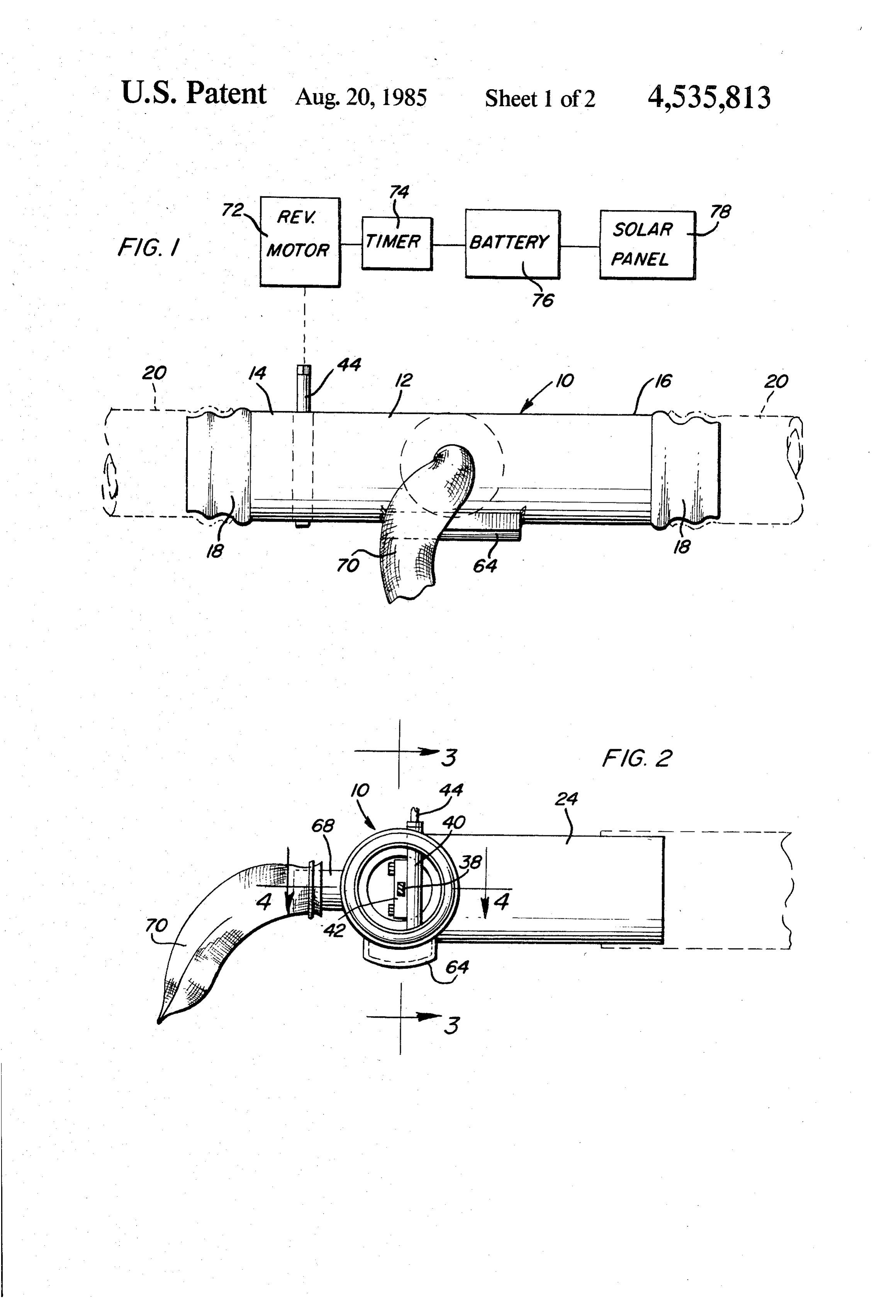
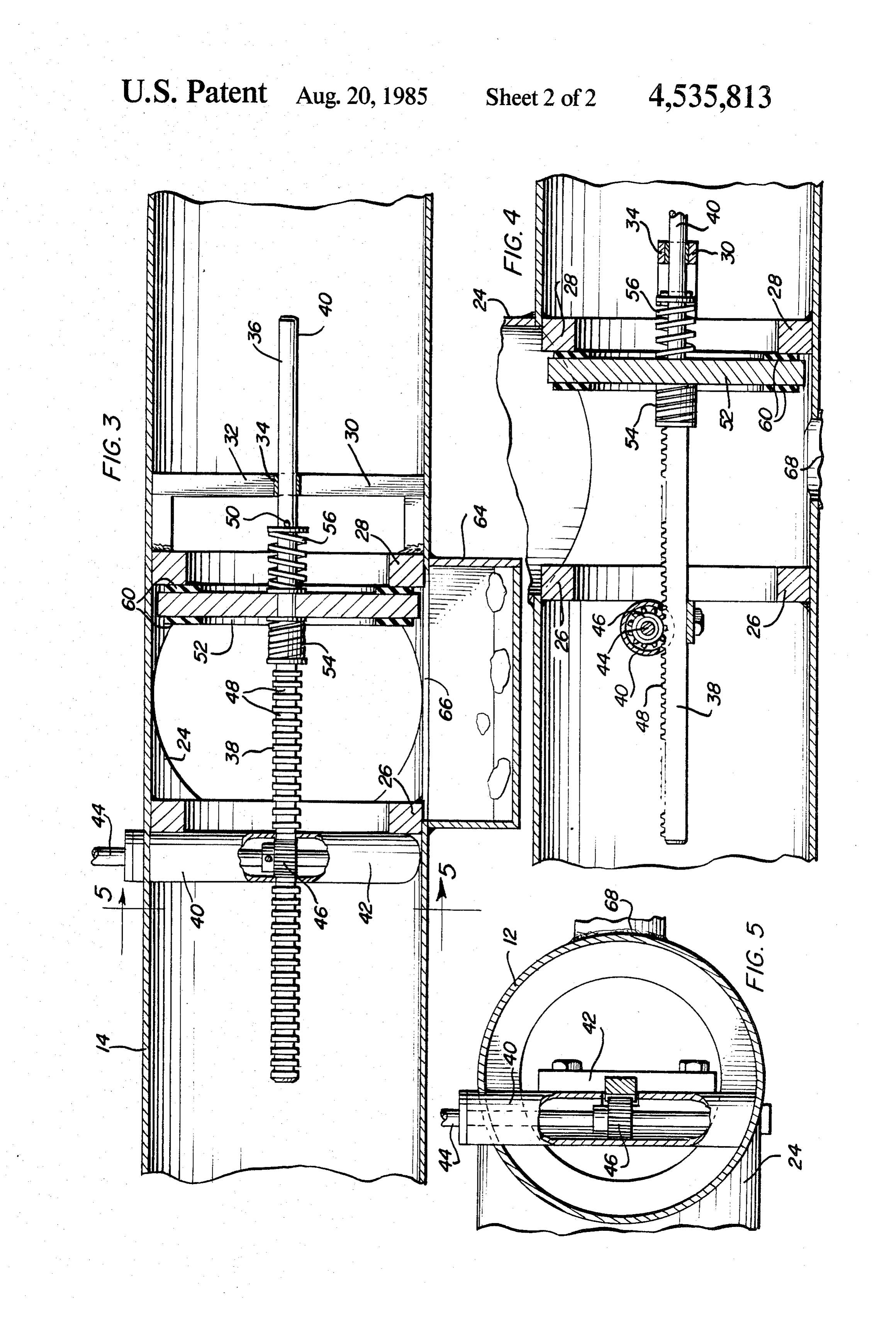
2. Description of the Related Art BRIEF DESCRIPTION OF THE DRAWINGS Various different forms of electrically controlled and FIG. 1 is a side elevational view of the surge valve of programmable timed valves heretofore have been pro the instant invention with the drive mechanism for the vided as well as other forms of valves including some of 20 valve member of the valve being schematically illus the general structural and operational features of the trated;
instant invention. Examples of some of these previously FIG. 2 is an end elevational view of the surge valve known forms of valves are disclosed in U.S. Pat. Nos.
as seen from the right side of FIG. 1;
645,696, 916,403, 1974,335, 2005,891, 2,327,959, FIG. 3 is an enlarged fragmentary longitudinal verti cal sectional view taken substantially upon the plane
SUMMARY OF THE INVENTION indicated by the section line 3-3 of FIG. 2; The valve of the instant invention comprises a surge tional FIG. 4 is an enlarged fragmentary horizontal sec valve having a rack and pinion drive assembly for recip by theview taken substantially upon the plane indicated rocally shifting a valve member between two outlet 30 FIG.section 5 is a line 4-4 of FIG. 2; and fragmentary vertical sectional view taken seats. The rack and pinion drive assembly includes an Substantially upon the plane indicated by the section electric drive motor to which electrical current is sup line 5-5 of FIG. 3.
plied from a battery pack and the battery pack is re charged by a solar cell. The valve member, when being DESCRIPTION OF THE PREFERRED driven by the drive assembly, moves slowly from one 35 EMBODIMENT seat toward the other seat and the movement of the valve member between the two seats is relatively slow Referring now more specifically to the drawings the and the valve thereby functions to gradually open one numeral 10 generally designates the surge valve assem outlet of the valve while gradually closing the other bly of the instant invention. The assembly 10 includes an outlet of the valve. This prevents pressure surges and 40 elongated tubular body 12 including opposite end por sudden thrusts of water from the valve seat being tions 14 and 16. The terminal ends of the end portions 14 opened. Further, the valve member includes a lower and 16 are specifically shaped as at 18 for releasable Sump for collecting any large solids which may enter coupling to irrigation pipe sections 20 and the longitudi the valve by the flow of water supplied to the valve. nal mid-portion of the body 12 includes a water inlet The sump is operative to contain a considerable quan 45 neck 24 opening into the interior of the hollow body 12. tity of large solids which might otherwise interfere with The end portions 14 and 16 include annular valve shifting of the valve member between the two seats seats 26 and 28 secured therein and it may be seen from with which the valve member is engageable. Further, FIGS. 3 and 4 of the drawings that the inlet neck 24 is the valve member is spring-mounted on the support disposed between the remote sides of the annular valve therefor which supports the valve for movement be SO seats 26 and 28.
tween the two seats and the spring-mounting of the Inasmuch as the body comprises a cylindrical body valve prevents injury to the drive mechanism for the and the valve seats 26 and 28 comprise annular seats valve member in the event an obstruction is disposed secured within the body 12 in planes disposed normal to between the valve member and the seat toward which the longitudinal centerline of the body 12, the seats 26 the valve member is being moved. 55 and 28 are axially spaced and coaxial. The main object of this invention is to provide a The end portion 16 includes a U-shaped mount 30 lightweight surge valve that can be handled by almost secured therein and mounted from the side of the seat 28 any person. remote from the seat 26. The bight portion 32 of the Another object of this invention is to provide a fully mount 30 is vertically disposed and includes a central Self-contained surge valve-equipped system which re 60 guide sleeve 34 extending therethrough. quires no external power source. An elongated support 36 is provided including a first Yet another important object of this invention is to rectangular cross section end portion 38 and a second provide a surge valve having a sump in a lower portion cylindrical end portion 40. The end portion 40 is guid thereof for collection of obstructions which could possi ingly and slidingly received through the sleeve 34 and bly cause valve malfunction. 65 the end portion 14 includes an elongated vertically Another object of this invention is to provide a surge disposed journal assembly 40 from which a guide block valve including a valve member shiftable between op 42 is removably supported and the guide block 42 slid posing valve seats under the control of a drive mecha ably and guidingly supports the end portion 38. The 5 journal assembly 40 comprises a tubular support se rate of discharge of water into each furrow may not be cured in the body 12 and upwardly through an upper sufficient to allow the irrigation water to flow the full wall portion of the body and the journal assembly 40 length of each furrow. However, through utilization of rotatably journals a driven shaft 44 therein having a the surge valve, a full available rate of water flowing to pinion gear 46 mounted thereon. The end portion 38 5 the valve 10 may be initially diverted for irrigating only includes rack gear teeth 48 formed thereon and spaced one set of furrows and then switched for irrigation of a longitudinally therealong and the pinion gear 46 is second set of furrows. In this manner, the entire amount meshed with the rack gear teeth 48. Accordingly, upon of a limited supply of water to the valve 10 may be oscillation of the shaft 44 the elongated support 40 will alternately supplied to two different sets of furrows. be longitudinally rectilinearly reciprocated. O It will be noted that the seats 26 and 28 are mounted The end portion 36 includes a diametric abutment pin in such a manner within the end portions 14 and 16 to 50 secured therethrough intermediate the opposite ends prevent communication between the interior of the of the end portion 36 and a circular valve disc or ele sump 64 and the end portions 14 an 16 other than ment 52 is slidably mounted on the end portion 36 be through the valve seats 26 and 28. In addition, the valve tween the pin 50 and the end portion 38. A pair of com 5 seats 26 and 28 are further mounted within the body. 12 pression springs 54 and 56 are disposed about the end to prevent communication between the inlet neck 24 portion 36 on opposite sides of the valve disc 52. The and the end portions 14 and 16 other than by through adjacent ends of the springs 52 and 56 abut the opposing the seats 26 and 28.
axial faces of the valve disc 52 and the remote ends of The foregoing is considered as illustrative only of the the springs. 54 and 56 abut against the end portions 38 principles of the invention. Further, since numerous and the pin 50, respectively. Accordingly, the springs modifications and changes will readily occur to those 54 and 56 serve to yieldingly bias the valve disc 52 skilled in the art, it is not desired to limit the invention toward a centered position between the end portion 38 to the exact construction and operation shown and and the pin 50. Further, the valve disc 52 includes oppo described, and accordingly, all suitable modifications site axial end outer peripheral resilient annular seals 60 25 and equivalents may be resorted to, falling within the for cushioned fluid-tight sealed engagement with the scope of the invention.
seats 26 and 28. What is claimed as new is as follows: The journal assembly 40 and drive shaft 44 project 1. An irrigation surge valve including a hollow tubu upwardly through the upper portion of the tubular lar body defining opposing axially spaced annular outlet body 12 and the lower portion of the tubular body 12 seats, said body including an inlet opening into said includes an upwardly opening hollow sump 64 which body intermediate said seats, an elongated support projects, downwardly from the undersurface of the mounted in said body for guided recilinear movement body 12. The sump 64 is in the form of an upwardly between first and second predetermined positions, a opening housing secured about an appropriately shaped valve disc slidably mounted on said support for shifting opening 66 formed in the underside of the body 12 35 therealong between relatively axially displaced limit between the seats 26 and 28. Further, the side of the positions, means operatively connected between said body 12 remote from the inlet neck 24 includes an out disc and support yieldingly biasing said disc toward an wardly projecting outlet neck 68 of considerably intermediate position on said support between said limit Smaller inside cross-sectional area than the inlet 24 and positions, said disc being alternately sealingly engage having a water pervious bag-type filter cover 78 se able with said seats upon alternate shifting of said sup cured thereover. port between said predetermined positions, reversible With attention now invited more specifically to FIG. motor means operatively connected to said support for 1 of the drawings it may be seen that the driven shaft 44 shifting said support between said first and second pre projects upwardly from the body 12 and has a revers determined positions, said body including upper and ible electric motor 72 drivingly coupled thereto. The 45 lower sides and said lower side defining an internal electric motor 72 is supplied operating current through upwardly opening sump communicated with the inte a programmable timer 74 from a gel pack storage bat rior of said body between said seats and disposed below tery 76 and a solar panel 78 is operatively connected to the path of movement of said disc between aid seats, the battery 76 for recharging the latter. The timer in said body further including a third outlet of smaller cludes a Switching mechanism which reverses the 50 cross-sectional area than the effective flow cross-sec motor 72 each time the motor 72 is actuated by the tional area of said outlet seats, said third outlet opening timer and the time interval between periods of actuation into said body intermediate said seats and generally of the motor 72 may be preset at the timer. Also, the opposite from said inlet opening, said third outlet being motor and timer may be interconnected in such a man disposed above the level of said sump. ner that increased resistance to operation of the motor 55 2. The valve of claim 1 wherein said third outlet will be sufficient to terminate operation of the motor. In includes a water pervious bag-type cover filter secured this manner, the motor 72 may be used to alternately thereover externally of said body.
shift the valve disc 52 between positions in seated en 3. The valve of claim 1 wherein said motor means gagement with the valve seats 26 and 28. comprises a reversible electric motor, a control mecha It is extremely important to note that the valve 10 is 60 nism operatively connected to said motor for controlled operative in many inrrigation environments and that it operation thereof, said control mechanism including is particularly well adapted for use in an irrigation envi means operative to reversibly operate said motor at ronment in which the rate of water being supplied to the variable timed intervals.
valve 10 through the inlet neck 24 is not sufficient to 4. The valve of claim 3 wherein said control mecha alow continued and simultaneous discharge of water 65 nism also includes a storage battery and a solar panel for from both end portions 14 and 16. If a limited intake of recharging said battery, said battery being electrically water to the valve 10 is continuously discharged from connected to said motor through a timing and switching the end portions 14 and 16 into two sets of furrows, the mechanism.
Page 6scan →
5. The valve of claim 1 wherein said support includes ment means with said springs partially compressed one end portion thereof provided with rack gear teeth, when said disc is centered between said abutment said motor means being disposed externally of said body means, said first end portion of said elongated support and including a rotary output shaft projecting into said member including rack gear means extending longitudi body and having a pinion gear mounted thereon method nally therealong, said drive means including a reversible with said rack gear. motor driven pinion gear journalled from said first sup 6. An irrigation surge valve including a hollow tubu port means and meshed with said rack gear means, lar body including longitudinally spaced opposing an 7. An irrigation Surge valve including a hollow tubu nular outlet seats, said body including an inlet opening lar body including longitudinally spaced opposing an into said body intermediate said seats, a valve disc, O nular annular outlet seats, said body including an inlet mounting means mounting said disc in said body for opening into said body intermediate said seats, a valve axial shifting therealong between relatively axially disc, mounting means mounting said disc in said body spaced limit positions sealingly engaged with said seats, for axial shifting therealong between relatively axially drive means operatively connected to said disc for shift spaced limit ing said disc between said limit positions, said body 15 drive means positions sealingly engaged with said seats, operatively connected to said disc for shift including upper and lower sides, said lower side defin ing an internal upwardly opening sump within said ing said disc between said limit positions, said body body, between said seats and disposed below the path of including upper and lower sides, said lower side defin movement of said disc between said seats, said mount ing an internal upwardly opening sump within said ing means including an elongated support upon which 20 body, between said seats and disposed below the path of said disc is generally coaxially mounted for limited movement of said disc between said seats, said body sliding therealong, first and second support means in including a third outlet of smaller cross-sectional area said body spaced longitudinally therealong on remote than the effective flow cross-sectional area of said outlet sides of said seats guidingly engaging first and second seats, said third outlet opening into said body intermedi end portions, respectively, of said elongated support 25 ate said seats and generally opposite from said inlet member for guided reciprocation of the latter longitudi opening, said third outlet being disposed above the level nally of said tubular body, longitudinally spaced abut of said sump.
ment means on said elongated support spaced on oppo 8. The valve of claim 7 wherein said third outlet site sides of said disc, and coiled compression springs includes a water pervious bag-type cover filter secured disposed on said elongated support member on opposite 30 thereover externally of said body. sides of said disc and between the latter and said abut : k 2:
Provenance
- Collection
- Patents citing this work
- Pages
- 6
- Method
- pdftotext (the PDF's own text layer) + pdftoppm 300dpi page scans
- Patent office record
- patents.google.com →
- Source
- Google Patents citing-documents table
- Assignee
- Spain Robin L
- Published
- 1985-08-20
- Transcribed from
- patentimages.storage.googleapis.com →