

patent · US4102754A
Ore treatment electrolytic cell
25 July 1978
Text
Page 1scan →
Hedges et al.
[73] Assignee: Electro-oxidation Systems, Inc., Oakland, Calif.
588,740 8/1897 Becker ................................. 204/275
Primary Examiner-T. M. Tufariello
Attorney, Agent, or Firm-Flehr, Hohbach, Test, Albritton & Herbert
An electrolytic cell assembly for the treatment of an ore slurry including a number of flowthrough cells formed between spaced parallel electrode plates. Slurry is fed to the bottom of the cell assembly through slots in a non-conductive manifold connected to outlet pipes from a stream splitter which is connected with a main slurry conduit.
10 Claims, 7 Drawing Figures
Drawings
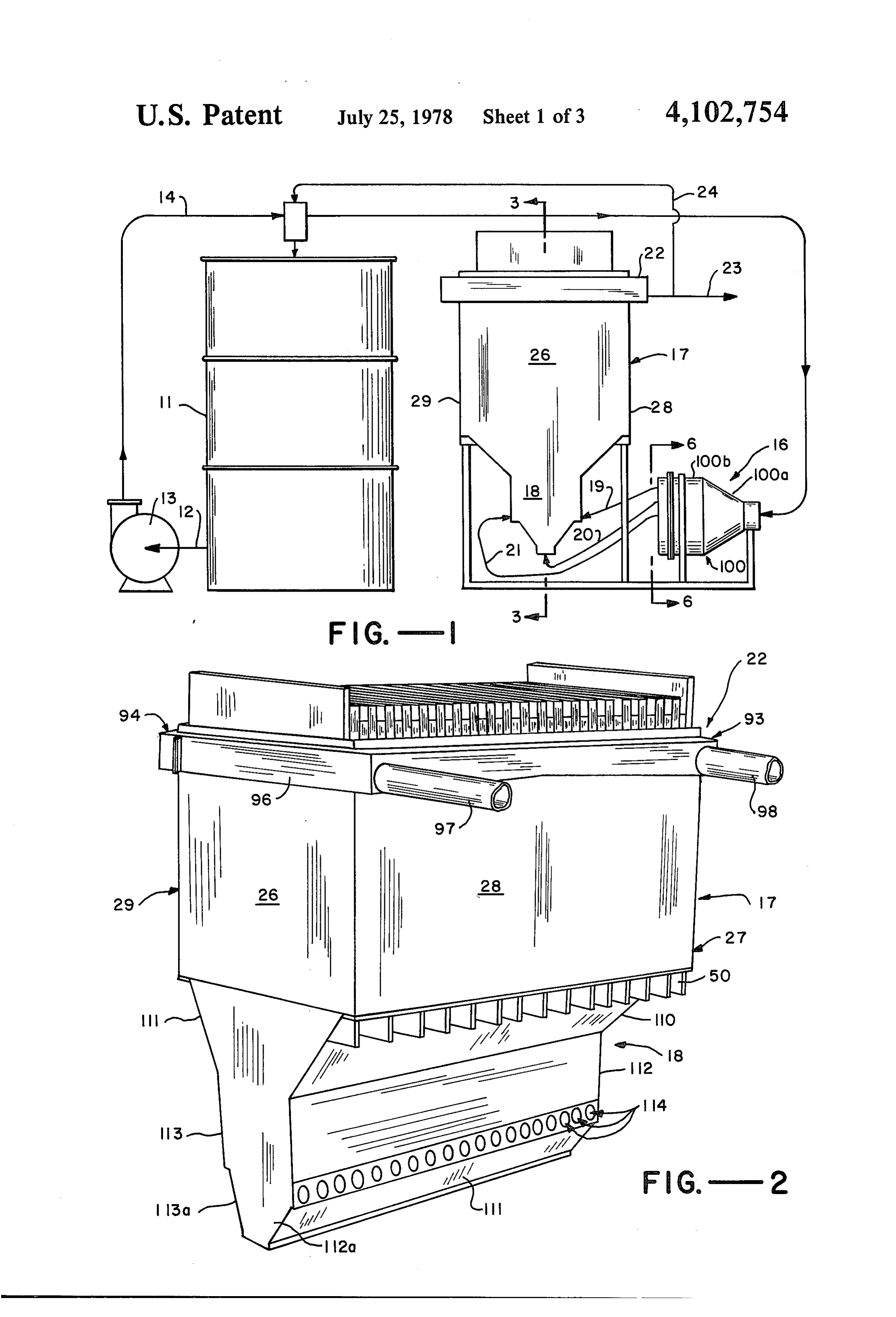
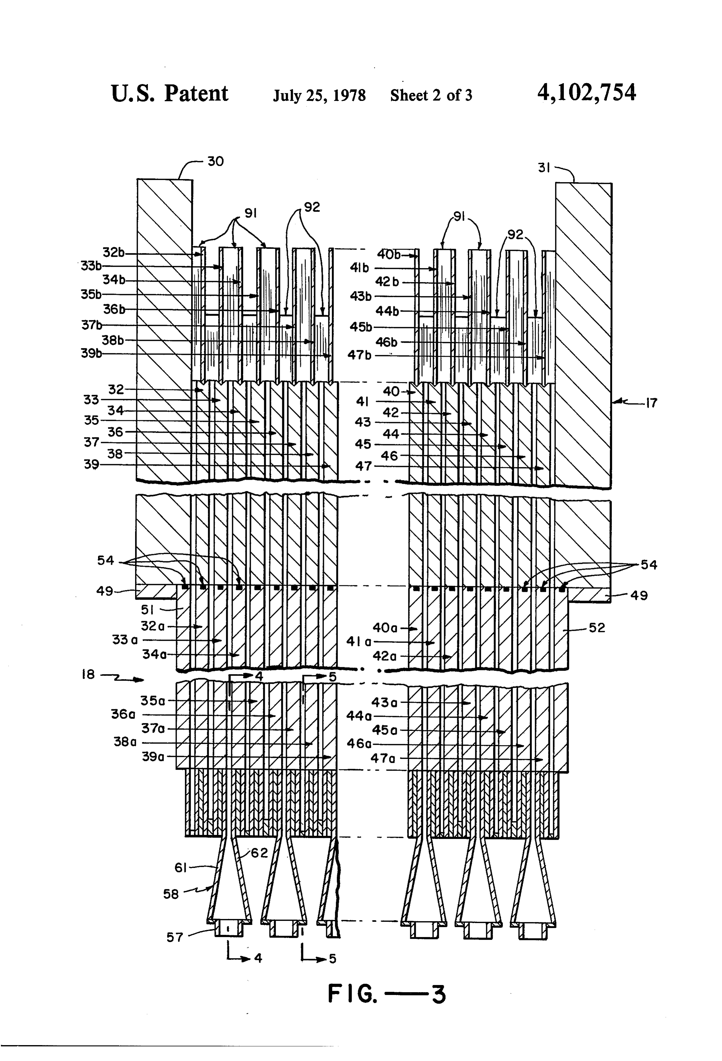
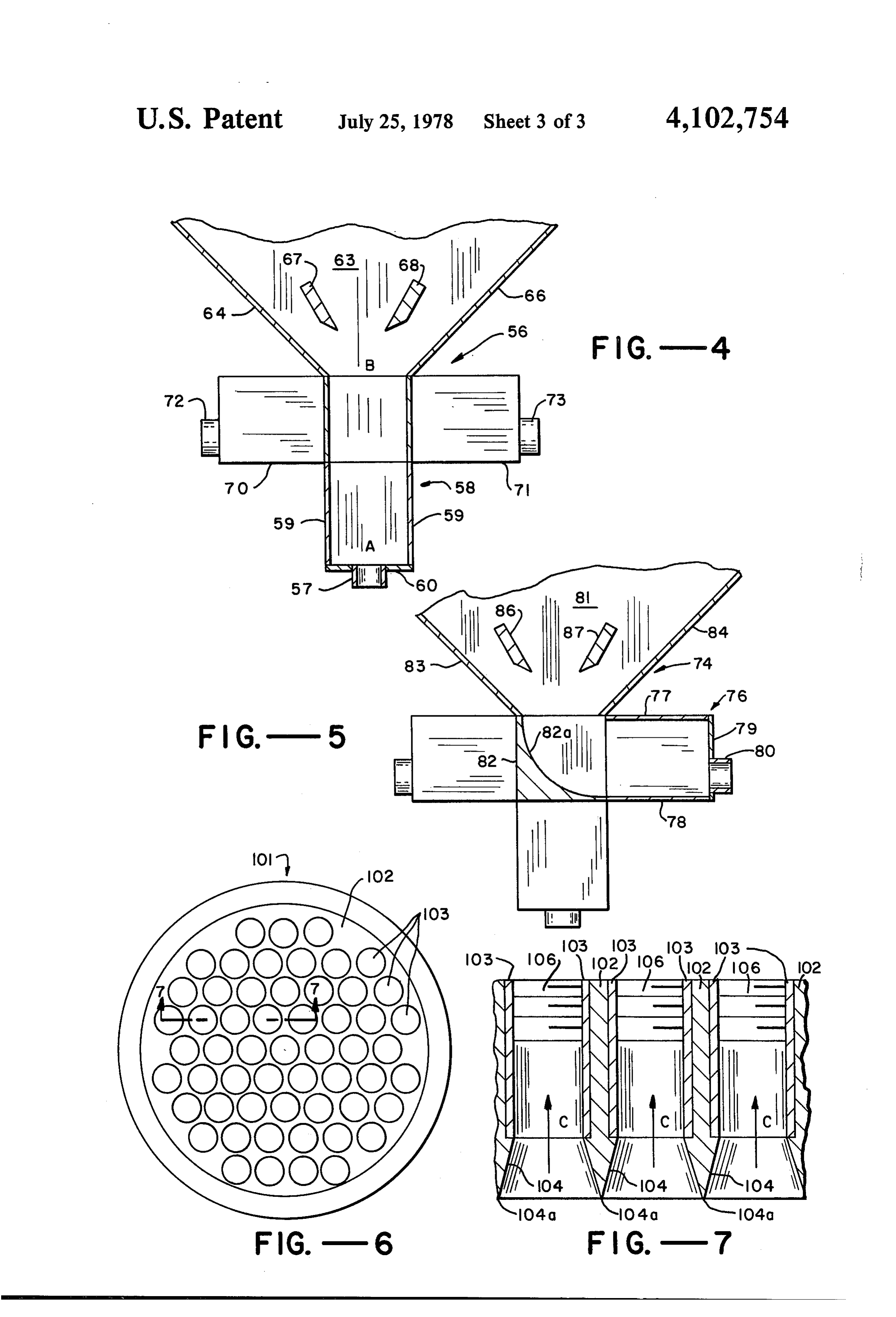
FIG. 7 is an expanded cross-sectional view of a por Non-conductive side walls 26 and 27 and front and rear tion of FIG. 6 taken along the line 7-7 illustrating the walls 28 and 29, respectively, form a liquid tight box in inlet side of the stream splitter assembly of FIG. 6. combination with manifold section 18 to be described
Page 2drawing sheetscan →
Page 3drawing sheetscan →
Page 4drawing sheetscan →
Page 5scan →
A bipolar electrolytic cell for the electrolytic oxida
ORE TREATMENTELECTROLYTC CELL tion of sulfide ores to recover molybdenum is disclosed BACKGROUND OF THE INVENTION in U.S. Pat. No. 3,849,265. There, the slurry is illus trated as being directed to the bottom of a tank with
Electrolytic oxidation of various ores is advantageous upright electrodes forming separate cells. The inlet is in comparison to conventional techniques for various through a common reservoir or plenum and so is subject types of ores. For example, in one conventional process, to the type of power losses as set forth above with molybdenum is recovered by a combination of multi respect to Australian Pat. No. 464,246.
stage flotation techniques and roasting. However, such processing is relatively costly, the molybdenum recov 10 Summary of the Invention and Objects ery is extremely low, and the roasting of sulfide concen In accordance with the present invention, an electro trate causes heavy atmospheric pollution. Similarly, the lytic cell is provided for the treatment of an ore slurry recovery of mercury has been performed by a pyromet formed of a number of facing spaced electrode plates allurgical process which constitutes a health hazard with slurry flowthrough passages therebetween. The unless careful precautions are taken. 15 cells are fed through manifolds including non-conduc
Because of the above problems, electrolytic oxidation tive walls defining slots having inlets connected to indi has been employed for the recovery of mercury from vidual slurry feed pipes and outlets adjacent to the inlets mercury-bearing materials as set forth in Australian Pat. of the cell flowthrough passages. The manifold includes No. 464.246. There, an electro-oxidative cell is dis a flow area expansion section, preferably of a truncated closed in which the slurry is directed from a common 20 triangular cross-section for converting flow conduit into an open lower plenum chamber in direct transition from the slurry feed pipes to theinindividual a smooth communication with electrolytic cells formed in the electrolytic cells. Preferably, the individual feed pipes spacing between multiple parallel upright electrode are connected through a stream splitter assembly to a plates. The overflow from the plates is removed main slurry source conduit. An assembly is provided for through ports connected in a common trough. 25
There are a number of problems created with respect receiving the overflow slurry from the cells and direct ing the same to collectors located at opposite sides of to cell assemblies of the foregoing type. Firstly, the the cell.
common inlet plenum for the electrolytic cells creates a In accordance with the present method, cells of the major flowpath for stray voltage which reduces the foregoing types are employed to split the ore slurry into electrical efficiency of the cells and thereby greatly 30 increase the power required for the electrolytic process. independent streams which are directed through inde Similarly, overflow of the cell is at a common outlet pendent elongate slots defined by a manifold into the trough with a corresponding possibility of a stray volt electrolytic cells. The cel assembly may be periodically age path. back-flushed for cleaning because there are no major A modification of such cell has been developed in an 35 constrictions.
attempt to avoid excessive power consumption. There, It is an object of the invention to provide an appara slurry is supplied to the bottom of the cell flow path tus having multiple electrolytic cells suitable for treat between spaced electrodes of the foregoing types ment of an ore slurry which maximizes power effi through a series of spaced inlet pipes which extend ciency.
across all cells. Such inlet pipes are connected to a 40 It is a particular object of the invention to reduce common manifold conduit and include inlet spray-type power losses due to stray voltages in electrolytic cells. openings for each cell. It is a further object of the invention to provide a cell There are many problems inherent in this modifica assembly of the above type capable of treating ore slur tion. Firstly, it is very difficult to control this type of ries with relatively large particle size, of treating slurry flow to obtain uniform pressure across the bottom of 45 at rapid flow rates uniformly in each cell. each cell. Uneven pressures cause variance in cell flow It is another object of the invention to provide cells of rates which creates unequal treatment for the slurry the foregoing type in which the power requirement for flowing through various portions of the cell. Addition pumping through the cells is minimized. ally, spraying the slurry through such inlet holes causes It is an additional object of the invention to minimize a significant pressure drop with a corresponding high 50 turbulence in the above type of cell. power consumption for operation of a pump. Further objects and features of the present invention Another problem with the modified cell is that the will be apparent from the following description taken in total volumetric flow through the cell is limited by the conjunction with the accompanying drawings. use of inlet holes in the pipes. Furthermore, the maxi mum particle size of the slurry is limited because it must 55 BRIEF DESCRIPTION OF THE DRAWINGS pass through such openings. A further problem is that FIG. 1 is a general schematic flow-diagram of appa cells of the above type tend to accumulate particulate ratus in accordance with the present invention. materials such as reaction products which tend to plug FIG. 2 is an isometric view of an electrolytic cell the openings. A system with small inlet openings of the assembly in accordance with the present invention. above type is not adapted to back flushing to clean out FIG. 3 is a cross-sectional view of the electrolytic cell residues in the cell. assembly of FIG. 1 taken along the line 3-3. A further problem with the above type of modified FIGS. 4 and 5 are cross-sectional views taken along cell is that a common voltage path is presented across the lines 4-4 and 5-5, respectively, of FIG. 3, illus the various cells through the liquid in the pipes prior to trating different types of inlets for a cell assembly mani entrance into the cells. Although such path is more 65 fold.
efficient in power consumption than the cell which it FIG. 6 is a view taken along the line 6-6 of FIG. 1 replaced, a substantial power loss remains due to this illustrating the outlet side of the stream splitter assem voltage leakage. bly.
Page 6scan →
FIG. 7 is an expanded cross-sectional view of a por Non-conductive side walls 26 and 27 and front and rear tion of FIG. 6 taken along the line 7-7 illustrating the walls 28 and 29, respectively, form a liquid tight box in inlet side of the stream splitter assembly of FIG. 6. combination with manifold section 18 to be described
Detailed description of the
hereinafter. The interior of cell assembly 17 is best illus trated with respect to FIG. 3. A large anode end plate
PREFERRED EMBODIMENTS 30 and opposing end plate 31 are mounted to abut The electrolytic cell assembly of the present inven against side walls 26 and 27 and are interconnected tion will be described first with reference to the overall suitably by copper bus bars to a source of direct current flow system of the present invention illustrated in FIG. to form a bipolar cell. Between plates 30 and 31 are 1. The cell assembly finds particular use for the electro 10 disposed parallel spaced vertical electrode plates 32 lytic oxidative treatment of a variety of ores in slurry 47, inclusive, numbered in consecutive order. The form. In one process of this type, described in U.S. Pat. spaces between adjacent electrode plates comprise inde No. 3,639,222, mercury is extracted from mercury-bear pendent cell flowthrough passages. For simplicity of ing materials by electrolytic oxidation in an electrolytic drawing, only a portion of the flowthrough passages are salt solution. Another type of system, illustrated in U.S. 15 illustrated in FIG. 3. w Pat. No. 3,849,265, describes the recovery of molybde The end of plates and central electrode plates are num and rhenium values in sulfide-type ore in which the preferably formed of graphite. However, other elec source is pulverized and electro-oxidized in an aqueous trode materials may be employed if desired for specific salt solution in an electrolytic cell. For convenience of applications. The following description will assume the description, this latter type of oxidation treatment will 20 useSupport of graphite plates.
of the bottom portion of the end plates and be referred to as the specific system of the present in vention. However, it should be understood that other central electrode plates is preferably accomplished by electrolytic oxidation systems may also be carried out resting on the top surface of manifold section 18. One utilizing the present apparatus. purpose of the manifold section is to electrically isolate Referring to FIG. 1, aqueous slurry (pulp) of a typical 25 the individual cell flowthrough passages of each elec ore (low-grade molybdenite) is agitated in a stirred trolytic cell. Thus, section 18 is preferably formed of a surge and agitation tank 11. Then it is transferred in line structurally, strong non-conductive material, suitably a 12 to a pump 13 and directed through line 14 into the plastic, such as polyvinyl chloride. Referring to FIGS. inlet side of a stream splitter 16 of a structure to be 2 and 3, manifold section 18 includes wall sections 49 described in detail below. A number of slurry feed pipes 30 and ribs 50 mounted to the top of vertical side walls 51 from stream splitter 16 are directed to three different and 52 to support graphite end plates 30 and 31, respec inlet portions of bipolar electrolytic cell assembly 17 tively. A seal is formed at the interface between end including a lower manifold section 18. One series of plates 30, 31 and side walls 51, 52, suitably by providing such pipes, designated by the number 19, interconnect a grooves in the top of the walls in which O-rings are series of outlet openings of the stream splitter located at 35 mounted to maintain a seal under the pressure of grav the radially outward region of the stream splitter with ity. The central electrode plates 32-47 are supported in the near side of the manifold section 18. A second series a similar manner. That is, below each plate 32 - 47 is of feed pipes, designated by the number 20, intercon disposed a corresponding series of spaced generally nects an intermediate radial outlet region of stream aligned adjacent non-conductive slot walls 32a - 47a, splitter 16 with the bottom inlet openings of manifold 40 respectively. A liquid seal is formed at the interface 18. A third series of feed pipes, designated by the num between the slot walls and electrode plates by the provi ber 21, interconnect the central portion of the outlet of sion of O-rings seated in the grooves of the walls. Adja stream splitter 16 with the far side of manifold section cent slot walls, for example 32a and 33a, define slots 18. The reason for this type of pipe interconnection will with outlets generally adjacent to and in communica be set forth below. 45 tion with the inlets of the cell flowthrough passages After passage through manifold section 18, the ore defined by corresponding electrode plates 32 and 33. In slurry flows upwardly through a plurality of electro the illustrated embodiment, the slot outlets of manifold lytic cells defined by spaced electrode plates with flow 18 are of approximately the same size as the inlet flow through passages therebetween. In such cells, mineral through passages.
values in the slurry may be electrolytically oxidized. 50 The slots of manifold section 18 include an inlet open For example, the molybdenum values of a molybdenum ing of a type described in detail in FIGS. 4 and 5 and sulfide ore is converted to the soluble salt sodium mo interconnect with individual slurry feed pipes. The flow lybdate by electro-oxidation in the presence of a suitable diameter of the slurry feed pipes is substantially larger salt such as sodium carbonate as set forth in the afore than the flow spacing between the manifold slot walls at mentioned U.S. Pat. No. 3,849,265. After such treat 55 the inlet of the slots. The manifold includes a flow tran ment, the slurry is collected in a cell assembly outlet sition section defining a passage for gradual transition of means 22 to form a stream 23 which may be further flow from the feed pipes to the slots as set forth below. processed in accordance with known techniques. A Referring to FIG. 3, pipes 20 are directed into the portion of stream 23 may be recycled as stream 24 to bottom of manifold section 18 through a series of bot tank 11. tom flow transition sections, generally designated by The electrolytically oxidized slurry is then processed the number 56. Section 53 includes a plurality of flow by conventional techniques. For example, it may be modifying sections 58 terminating in cylindrical pipe passed to a suitable liquid-solid separator such as set adaptor nozzles 57. Section 58 also includes triangular tling tank from which the pregnant liquid is withdrawn wall 59, rectangular end wall 60 through which nozzle and passed to a suitable molybdate recovery unit such as 65 57 passes, and sloping side walls 61 and 62. Triangular an ion exchange unit. section 58 defines a chamber in which slurry flow from The electrolytic cell assembly 17 of the present inven a cylindrical pipe passing through nozzle 57 is con tion will now be described by reference to FIGS. 2 - 5. verted to conform to a rectangular slot having a width 7 comparable to that of an electrolytic flowthrough pas transition sections 56 and 74 is the provision of an inte sage and a length illustrated by the letter "A" in FIG. 4. rior wall 82 with a concave curved surface 82a for The apex of triangular section 58 terminates at the changing the direction of flow from horizontal to verti lower end of manifold flow area expansion section 63 cal in a smooth transition to avoid turbulence. In the with a cross-section transverse to flow of progressively illustrated embodiment, surface 82a is a quadrant of a increasing slot length in the direction of flow, in the circle with a lower end flush with the inner surface of upward direction as illustrated. Section 63 is defined by Wall 78.
sloping side walls 64 and 66 together forming an in The expansion section 81 includes sloping side walls verted truncated generally triangular cross-section 83 and 84. The bottom of wall 83 is mounted to the top taken along the path of flow through the slot. Walls 64 10 of flow-modifying section 76 so that the inner surface of and 66 are mounted to slot walls 33a and 34a of inverted the wall is flush against surface 82a. The bottom end of truncated triangular shape. The top of walls 64, 66, 33a wall 84 is mounted to the top of wall 77. Walls 83 and 84 and 34a define a maximum slot length at the interface of are mounted to the sides of triangular slot defining walls walls 33a, 34a, and end plates 33, 34, respectively. The 37a and 38a which terminate at their upper ends in cross-sectional of the slots at the interface is approxi 15 support edges for the corresponding electrode plates 37 mately the same size as the inlet of the cell flowthrough and 38 as described above.
passages. Baffles 86 and 87 are provided in the slot of section 81 Baffle plates 67 and 68 are provided in the line offlow to provide a smooth transition of flow and a uniform through section 63 to assist in uniform distribution of slurry flow rate across the transition section. As illus flowing slurry as the flow area is increased. The baffles 20 trated, baffles 86 and 87 are slightly off center towards are centrally disposed and are mounted to seal between wall 83 because the maximum flow pressure and thus the corresponding slot walls 33a and 34a. flow rate during the transition from a horizontal to a Referring again to FIG. 4, side flow transition section vertical direction will be toward that side of the section. 70 and 71 are illustrated including pipe adaptor nozzles As illustrated in FIG. 2, the flow transition sections 72 and 73. The interior of these flow transition sections 25 from the bottom and sides are formed of a unitary con will be described in more detail in FIG. 5. It is apparent struction bounded by exterior side walls to form a liquid that section 70 is connected to the inlet of the corre tight section through which the slurry pipe nozzles sponding flow transition section from the left side while project for connection to appropriate slurry inlet pipes. section 71 is connected from the right side, as illus As illustrated in FIG. 3, the seal between the elec trated. As is apparent from FIG. 3, the flowthrough 30 trode plates and corresponding slot walls is formed by passages would be too small to be fed from the rela individual O-rings. The seals to front and rear walls 28 tively large inlet pipes from a single direction because and 29, respectively, are also formed by continuing the there is insufficient space in any single plane to accomo same type of O-rings through corresponding vertically date multiple inlets. To overcome this problem, adja spaced slots in the walls for contact with the electrode cent transition sections are connected to the slot inlets at 35 plates. In this manner, electrode plates are sealed on sufficiently different angles of incidence so that the three sides by O-rings to prevent leakage' of liquid be connections of adjacent pipes and flow transition sec tween adjacent flowthrough passages with a corre tions occupy different segments of a cylinder generated sponding pathway for voltage leaks.
by a radius centered at the inlet of a slot designated by Referring to FIGS. 1 - 3, an outlet assembly gener the letter 'B' in FIG. 4. Thus, there is sufficient clear ally designated by the number 22 is illustrated for re ance for each of the flow transition sections with re ceiving slurry overflow after treatment in the electro spect to each other. In the illustrated embodiment, the lytic cells. The outlet assembly includes a series of ex angles of incidence of adjacent flow transition sections tension sheets 32b - 47b formed of a non-conductive are at approximately 90' with respect to each other. material such as polyvinyl chloride mounted to extend However, this may be varied depending upon the thick 45 upwardly from the corresponding electrode plates. ness of the transition sections to, say, from 30 to 100' High non-conductive barrier walls 91 are mounted with respect to each other. Referring again to FIG. 4, across one end of alternate pairs of extension sheets, three flow transition sections are connected to respec e.g., 33b, 34b, and 35b, 36b. Low barrier walls 92 are tive slot inlets, in order, from a left inlet side, from mounted an alternate sides of each high barrier wall at vertically below the slot inlet, and from a right inlet 50 the same end of the extension sheets and between adja side. cent sheets, e.g., 32b, 33b, and 34b, 35b. At the opposite Referring to FIG. 5, the cross-section of the left side side of the extension sheets, low barrier walls, not flow transition section 74 is illustrated. Section 74 in shown, are provided across the same pair of sheets cludes a flow-modifying section 76 connected with a provided with high barrier walls 91, while high barrier corresponding slurry feed pipe. Section 76 includes top 55 walls, not shown, are provided acress the same pair of and bottom walls 77 and 78 connected to a generally sheets provided with low barrier walls 92 at the oppo cylindrical end wall 79. A pipe adaptor nozzle 80 ex site end. In this manner, slurry in adjacent flowthrough tends through wall 79 for connection to a correspond passages flows over the top of the low barriers on alter ing slurry feed pipe. Section 76 is of generally the same nate sides of the extension sheets. V configuration as section 58 of the corresponding bottom 60 As illustrated, the extension sheets are sealed to the flow transition section 56. Thus, walls 77 and 78 are of top of the corresponding electrode plates in V-grooves generally triangular section corresponding to walls 59 with the bottom of the sheets being removably seated in of section 58 and are bounded by sloping side walls, not a highly viscous sealant such as silicon rubber. The shown, corresponding to walls 61 and 62. extension sheets and corresponding barrier walls are The outlet of flow-modifying section 76 is intercon 65 mounted in the cell assembly to form a unit of sufficient nected with the inlet side of flow expansion section 81 structural integrity to remain in a fixed position upon corresponding to section 63 of bottom flow transition the removal of one or more electrode plates through the section 56. The only structural difference between flow rear wall as described below.
Page 8scan →
Referring to FIG. 3, troughs 93 and 94 are provided and 113 through which side ports 114 and ports on the at opposite ends of the electrode plates and thus exten opposite side, not shown, project. Walls 112 and 113 sion sheets. A conduit 96 interconnects the two troughs terminating in sloped wall sections 112a and 113a, re so that liquid is removed through common outlet pipes spectively. Walls 112 and 113 are suitably formed by 97 and 98 for subsequent recombination into a single 5 placing that portion of manifold section 18 below walls outlet stream. The collection section defined by troughs 110 and 111 in a mold which is filled with a flowable 93 and 94 and conduit 96 and pipes 97 and 98 is remov plastic which solidifies leaving only the side and bottom ably mounted to the side walls of the cell assembly. ports exposed. This provides additional structural Similarly, the rear wall 29 of the cell is removably strength to the overall structure.
mounted to the remainder of the cell as with pressure 10 A brief description of the operation of the above adjustable bolts. In this manner, if it is desired to remove electrolytic cell is as follows. The ore material is first one or more individual electrodes for replacement, this ground as by passing through a crusher-ball mill combi may be accomplished by removing the collection sec nation. Grinding serves to expose the mineral in the host tion and then the back wall. rock for contact with the oxidizing conditions present at Referring to FIGS. 3, 6 and 7, a stream splitter assem 15 the anode of the system. The ground rock is then mixed bly 16 is illustrated for dividing the stream from a main in a stirred surge agitation tank 11. Assuming the unit is slurry line 14 into a sufficient number of individual used for the electro-oxidation of an aqueous slurry slurry feed lines for each flowthrough passage between (pulp) of a typical molybdenite ore, a slurry of the ore is facing electrode plates. As illustrated assembly 16 in charged into the tank together with aqueous brine solu cludes a stream splitter housing 100 with an inlet side 20 tion as set forth in U.S. Pat. No. 3,849,265. The ore is connected to the main slurry feed line 14 and expanding pulverized to, say, below 35 U.S. Standard Mesh with through a frusto conical section 100a to contact a split about 65% of the solid being below 200 mesh. ter member 101 formed of a solid plate 102 through The slurry is pumped from tank 11 by pump 12, suit which a desired number of individual cylindrical con ably rated at 75 hp, having a flow rate of 1200 gpm, duits 103 project as illustrated in FIG. 6. Splitter mem 25 solids concentration of 15 - 30 wt. percent, via main ber 101 is disposed perpendicular to flow in the cylin slurry 14 with an inner diameter of 8 inches to the inlet drical portion 100b of housing 100. Slurry flows in the side of stream splitter assembly 16. Then, the slurry direction of arrow 'C' in FIG. 7 through the individual expands in section 100a to fill cylindrical section 100b passages through conduits 103. Plate 101 terminates at and is split to flow in separate streams through individ an upstream surface in generally V-shaped projections 30 ual conduits 103 of splitter member 101. Conduits 103 104 forming points 104a. Projections 104 serve to direct are each mounted to slurry fred pipes (i.d. 1.30 inch) the slurry expanding through section 100a from a single generally designated as 19, 20 and 21. Flow in pipes 19 stream smoothly into the inlet side of conduits 103 with and 21 flow in opposing sides of manifold 18 while flow minimal turbulence. This lowers the pressure head re in pipes 20 flows to the bottom of the same. quirements for pump 13 and also serves to equally dis 35 Referring to FIG. 4, flow through a typical bottom tribute the slurry at fairly constant pressure to various inlet passes through nozzles 57 and into flow-modifying conduits 103. The outlet of conduits 103 are fitted with sections (e.g., 56 or 74) in which each stream is con suitable pipe adaptors such as threads 106 for intercon verted from the generally cylindrical configuration to a necting with conventional non-conductive slurry feed slot configuration of approximately 0.26 inch and a slot pipes, not shown, for manifold 18. length of 5 inches. Then, the slurs flows through flow As set forth above, the slurry flowing through the area expansion section 63 to reach a maximum slot radially outer conduits 103, being closest to the conical length of 4 feet. At this point, the slurry is at the same side wall of section 100a, is subject to maximum fric approximate size as the inlet to the respective cell slurry tional drag and so tends to have a slightly lower head flowthrough passages between spaced electrode plates. flow rate than the slurry at the center of splitter member 45 Then the liquid passes upwardly between the plates and 101. Thus, there is a gradual difference in slurry flow is subjected to electro-oxidation at the anodic plates. In rate through the pipes from a maximum at the center of the illustrated embodiment, the cell is of a bipolar type member 101 to a minimum at the outer periphery of the with a voltage of approximately 600 volts being applied same. In an attempt to equalize this flow rate, slurry from the anode end plate 30 to the cathode end plate 31. feed pipes 19 are directed from the outer periphery of 50 The current density is approximately 0.5 amp/sq.inch. conduits 103 to the nearest side of manifold 18. Simi The electrode plates between the end plates assume a larly, slurry feed pipes 21 from the central area of mem potential difference approximately equal to the total ber 101 travels to the most remote inlet of manifold 18. voltage drop between the end plates divided by the Finally, the slurry feed pipes 20 from the intermediate number of cell flowthrough passages. radial area of member 101 proceed through an interme 55 After electrolytic oxidation in the cell, the slurry diate distance to the bottom of manifold 18. In this overflows from opposite sides into independent troughs manner, the differences in the pressure drop within the over non-conductive extension sheets and barriers as pipes designated 19, 20 and 21 counterbalance for the described above. In this manner, the overflowing slurry pressure drop of the slurry exiting from various areas of from adjacent cell flowthrough passages is isolated to member 101. Thus, a substantial constant flow of slurry 60 prevent power loss due to stray voltage paths through is directed to the various cell assemblies. the liquid. Then, the slurry is collected at streams 97 and Referring to FIG. 2, manifold section 18 is illustrated 98 for conventional processing, such as of the type set in a stream-lined structurally reinforcing housing. The forth in U.S. Pat. No. 3,849,265. A portion of the over upper inverted frusto triangular section, corresponding flow may be recycled in line 24 to tank 11, if desired. to an assembly of all flow expansion sections, such as 63 65 The above system is characterized by many advan and 81, is enclosed by end walls 110 and 111 formed of tages over that of the prior art. For example, at the inlet non-conductive rigid plastic such as polyvinyl chloride. side of the cell assembly, the slurry streams are electri These walls are then attached to vertical side walls 112 cally isolated from each other from the time the slurry 9 passes through stream splitter 16 until it passes the cell 4. The cell apparatus of claim 1 together with baffle flowthrough passages. Such isolation reduces the means in the flow expansion area of said slots to pro power loss from stray voltage paths through the slurry. mote uniform flow of slurry through the same. - Another advantage with respect to power loss is the 5. The cell apparatus of claim 1 in which said mani manner of collecting overflow. Firstly, non-conductive fold means including individual flow transition sections upward extension sheets are provided with non-con each interconnecting one of said feed pipes and said slot ductive barriers to isolate the overflow streams and to inlets.
thereby minimize stray voltage paths. Furthermore, in 6. The cell apparatus as in claim 5 in which the flow diameter of said slurry feed pipes is substantially larger the indicated construction, the paths overflow alter than the flow spacing between said slot walls at the inlet nately to opposite sides to further electrically isolate of said slots, and said flow transition section defines a such streams. passage for gradual transition of flow from said pipes to A further advantage of the above system is that there said slots.
are no narrow constrictions. This permits efficient peri 7. The cell apparatus of claim 6 in which adjacent odic backflushing for claening by reversing the flow 15 transition sections are connected to said slot inlets at through the system with a washing liquid. Also, it pre sufficiently different angles of incidence so that the vents undue pressure drops and also enables the use of connection of adjacent ones of said pipes and flow tran relati-ely coarse particulate matter in the slurry to re sition sections occupy different segments of a cylinder duce the cost of expensive grinding of the particles. generated by a radius centered at the inlet of said slots What is claimed is: 20 to provide clearance for last named connections with 1. In an electrolytic cell apparatus suitable for treat respect to each other.
ment of an ore slurry, means forming a plurality of 8. The cell apparatus of claim 7 in which the angles of electrolytic cells comprising a plurality of spaced elec incidence of adjacent transition sections are from ap trode plates with cell slurry flowthrough passages as 9. The cell30apparatus proximately - 100' with respect to each other.
therebetween, manifold means for feeding slurry in three transitions sectionsofare claim 8 in which a series of connected to respective separate paths to the inlet side of each of said cell flow ones of said slot inlets, in order, from one inlet side, through passages, said manifold means including spaced generally vertically from the bottom, and from the adjacent non-conductive walls defining a plurality of other inlet side.
elongated slots of generally rectangular cross-section 30 10. In an electrolyte cell apparatus suitable for treat transverse to flow, each slot including separate inlets ment of an ore slurry, means forming a plurality of and outlets, individual slurry feed pipes in communica electrolytic cells comprising a plurality of spaced up tion with each of said slot inlets, a main slurry conduit, right electrode plates with cell slurry flowthrough pas and stream-splitter means interconnecting said main sages therebetween, slurry inlets formed in the lower region of each of said cells, outlet means formed in the conduit and feed pipes, the outlets of each of said slots 3 upper being adajcent to and in communication with the inlets extension region of said cells, said outlet means including of said flowthrough passages, said manifold means in sheets of non-conductive material mounted to extend upwardly from said electrode plates and also cluding a flow area expansion section with a cross-sec including collection means for receiving independent tion transverse to flow of progressively increasing slot 40 overflow streams length in the direction of flow. from opposite sides of said extension 2. The cell apparatus of claim 1 in which the cross tive sheets, said outlet means further including non-conduc section of said slots adjacent said flowthrough passages tension barrier walls across alternate pairs of adjacent ex is approximately the same size as the inlet of the flow anode and sheets, said last named sheets being mounted to through passages.
cathode plates, respectively, said barrier 45 walls blocking passage of liquid between the top of said 3. The cell apparatus of claim 1 in which the slots of flowthrough passages and said collection means, said flow expansion sections are of truncated generally whereby slurry in adjacent passages flows to collection triangular cross-section taken along the path of flow means on alternate sides of said extension sheets. through said slots. is sk ? ?
Provenance
- Collection
- Patents citing this work
- Pages
- 9
- Method
- pdftotext (the PDF's own text layer) + pdftoppm 300dpi page scans
- Patent office record
- patents.google.com →
- Source
- Google Patents citing-documents table
- Assignee
- Electrooxidation Systems, Inc.
- Published
- 1978-07-25
- Transcribed from
- patentimages.storage.googleapis.com →