

patent · US4137891A
Orbiting piston rotary engine
6 February 1979
Text
Page 1scan →
United States Patent (19)
Dalrymple
(54) orbiting piston rotary engine
76 Inventor: William P. Dalrymple, 415 W.
University, Rochester, Mich. 48063
51) int.C.’.............................................. FO2B 53/00 52 U.S.C. .................................... 123/245; 123/206;
1,317,909 10/1919 Deuel ................................... 123/245
3,927,329 12/1975 Fawcett et al. ................... 418/33 X
Foreign patent documents
1227082 2/1960 France. ... 123/245 496472 7/1954 Italy ..... ... 123/245 Primary Examiner-Carlton R. Croyle
Assistant Examiner-Michael Koczo, Jr.
Attorney, Agent, or Firm-Willis Bugbee
A rotary shaft carries a generally cylindrical composite rotor consisting of an inner cylindrical hub surrounded by a resilient undulatory spring sleeve which in turn is surrounded by a resilient cylindrical spring sleeve. Be tween the rotor and the internally cylindrical housing is an annular working chamber subdivided into compres sion and combustion chambers within which multiple cylindrical pistons of slightly greater diameter than the radial distance between the housing and rotor are snugly but orbitally rollable. Tangentially slidable in wedge-shaped recesses in the opposite end walls are upper piston-retarding wedges which are pushed back ward into temporary braking engagement with the op posite ends of a leading piston immediately forward thereof in response to the pressure of the exploding gases in the combustion chamber which also propel forward to exhaust ports a piston ahead of the leading piston. Meanwhile a trailing piston behind the wedges, propelled by compressed intake gases, pushes the wedges forward and apart and moves past them. Each piston is also retarded against backward motion by a unidirectional spring-pressed braking clutch mounted in an axial bore therethrough. The compression chamber is supplied with fuel gas through an intake port located circumferentially beyond a lower piston-retarding de vice located beyond the exhaust ports near the end of the combustion chamber. Timing of the ignition is ef. fected by a make-and-break device operated by one of the upper piston-retarding wedges in timed relationship with the orbiting pistons.
16 Claims, 10 Drawing Figures
Drawings
Page 2drawing sheetscan →
Page 3drawing sheetscan →
Page 4drawing sheetscan →
Page 5drawing sheetscan →
Page 6scan →
and 27, and has radial cooling fins 20 thereon with air
ORBITING PISTON ROTARY ENGINE channels 15 therebetween.
Summary of the invention
An upper piston retarder 28 is located at ten o'clock in an annular working chamber 32. Mounted in a
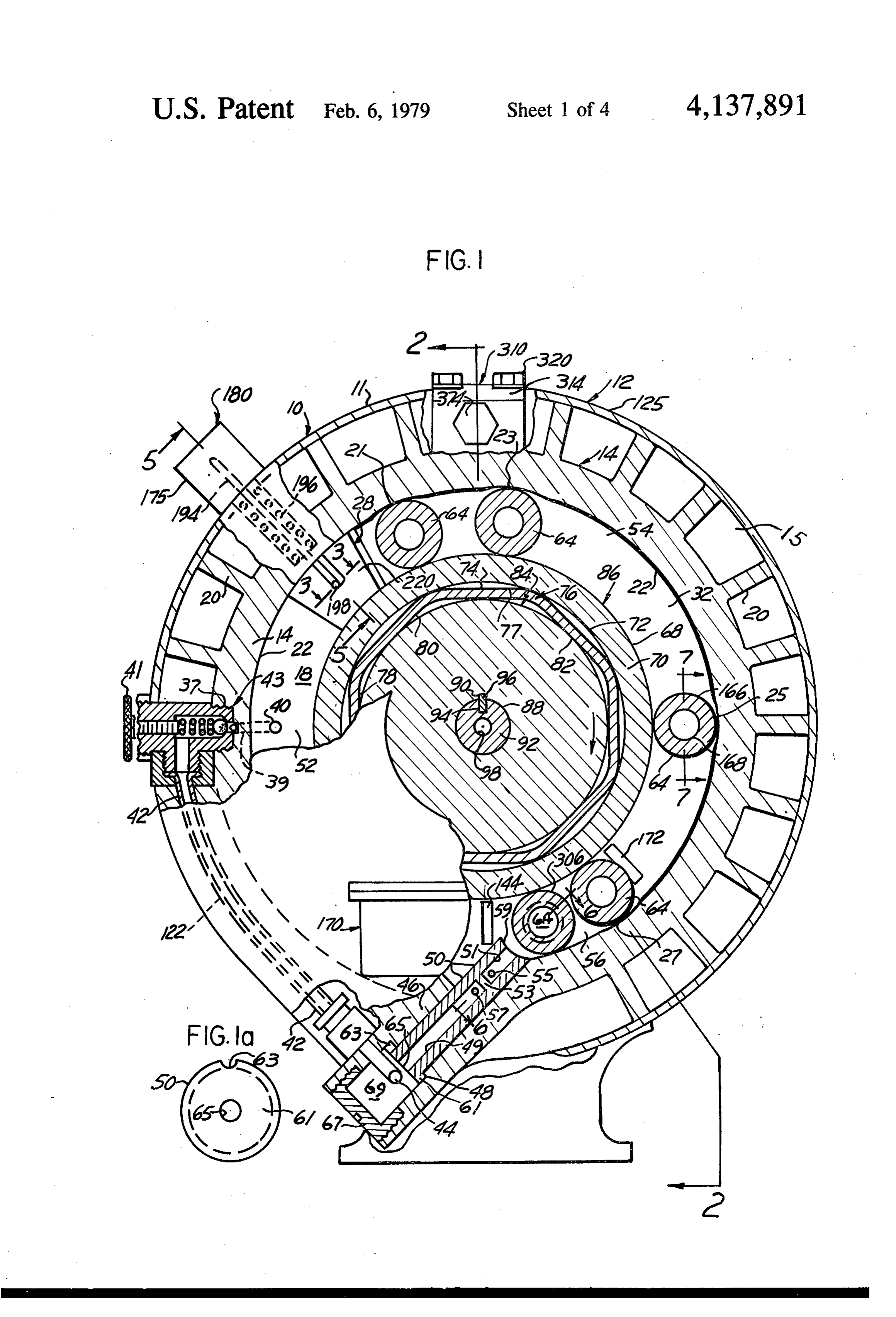
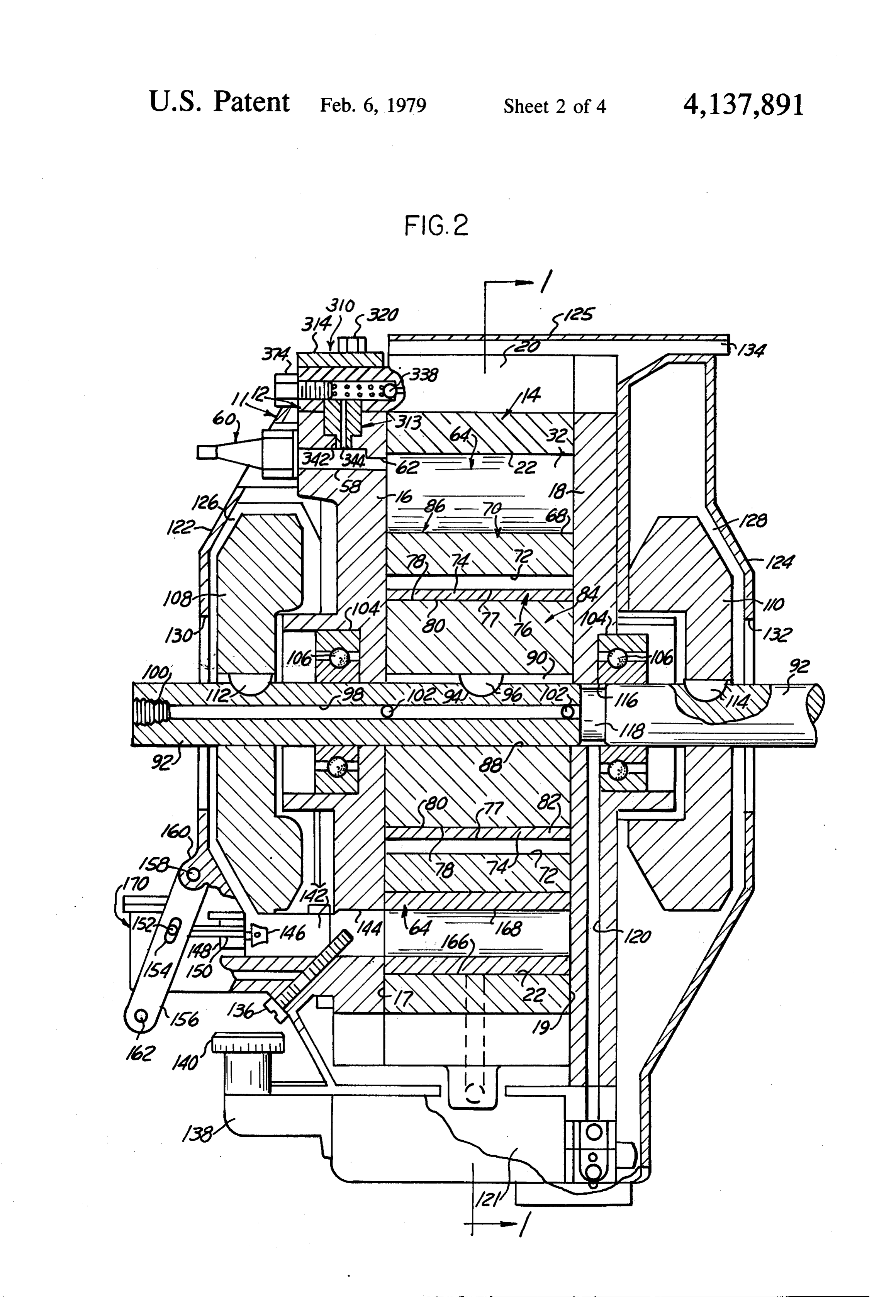
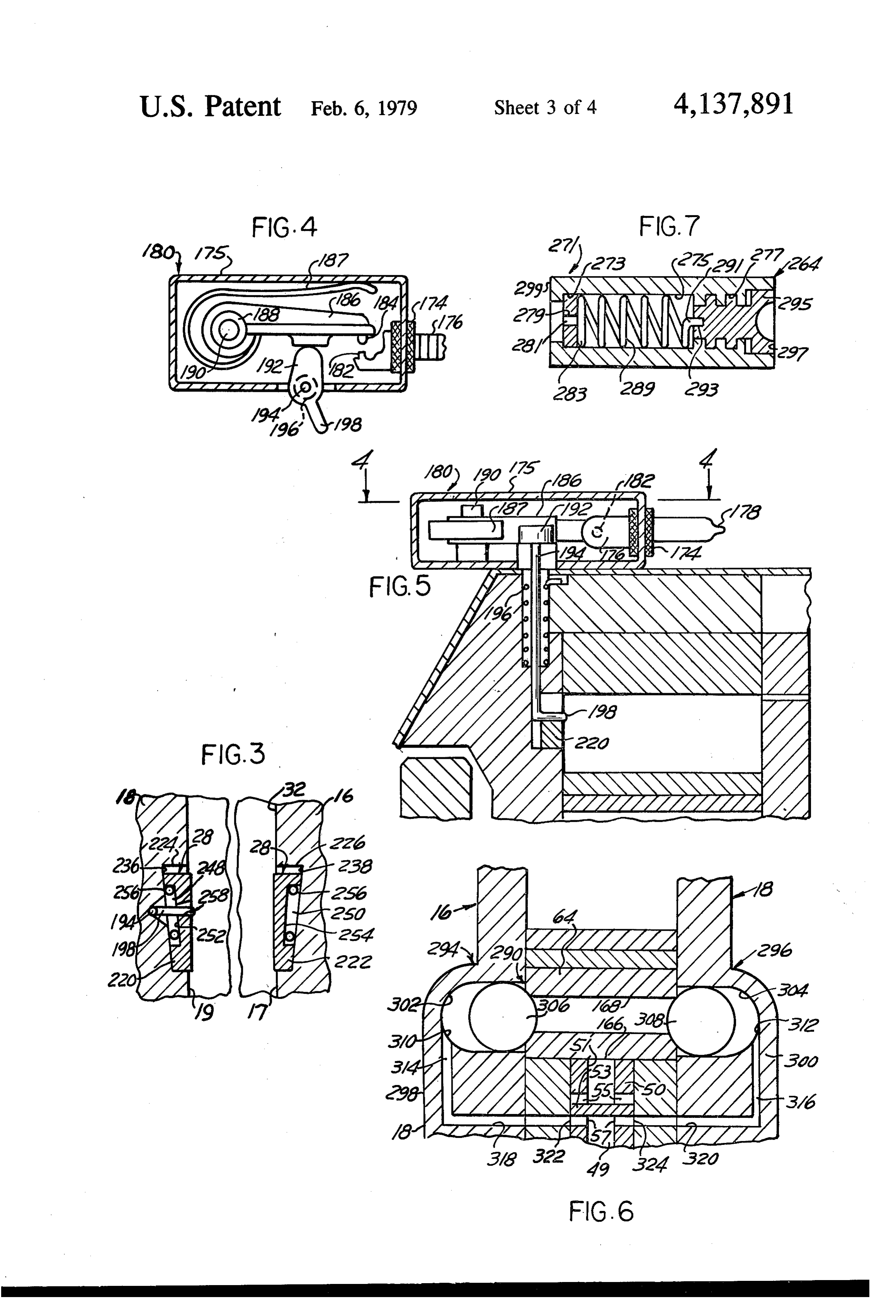
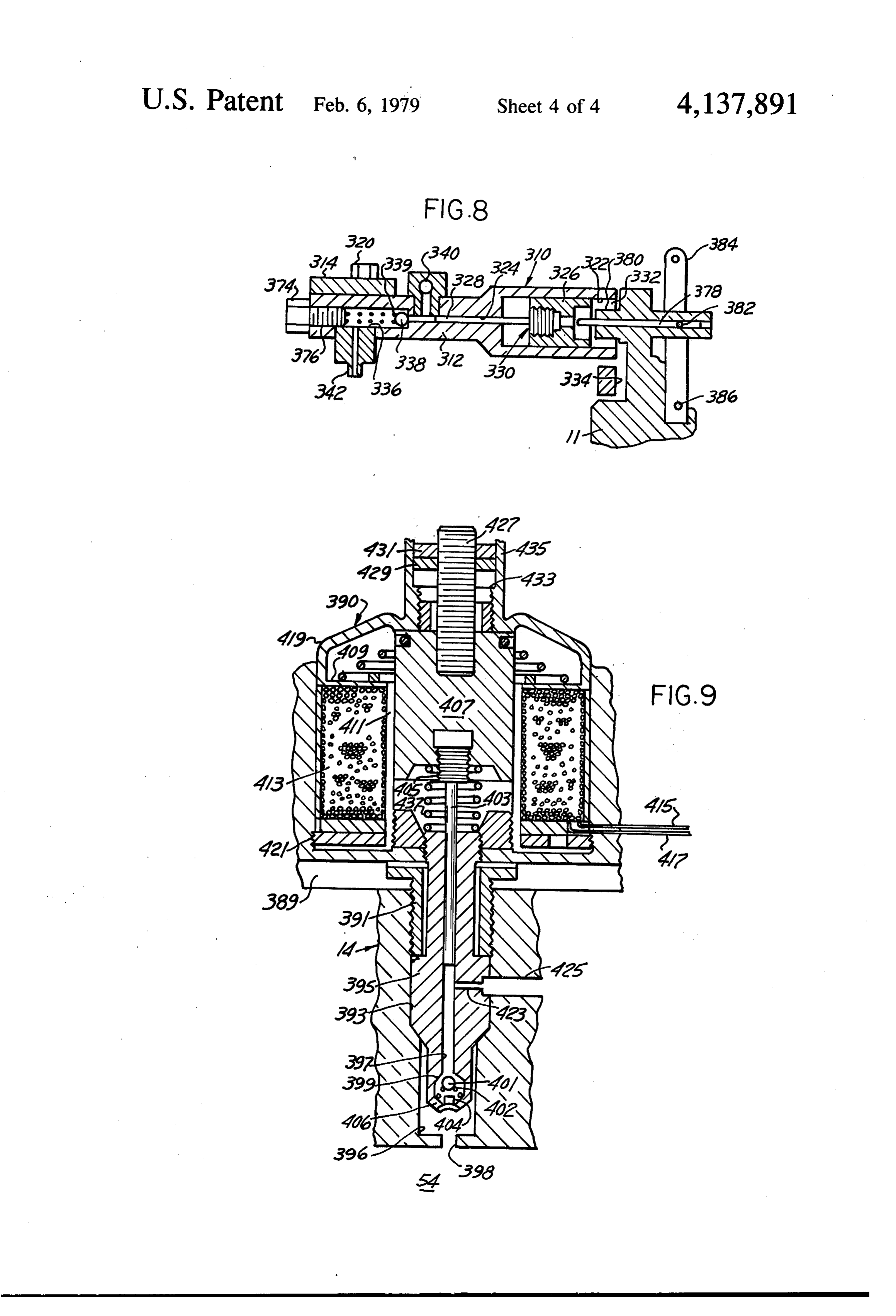
This invention resides in an engine in which the cylin 5 threaded bore 37 at the outer end of a passageway 39 drical pistons are caused to roll in orbital paths in an leading outward through the end head 18 from an inner annular working chamber between the generally cylin port 40 is a conventional adjustable spring-loaded ball drical coaxial surfaces of a stator and a rotor by the check valve 43 opening outward and having an adjust explosions of fuel gas introduced into the working ing screw 41. A pipe 42 between the end plates 16 and chamber while the trailing piston of a pair of such pis 10 18 runs downward from the valve 43 through notches tons is forcibly prevented by the upper retarding in the cooling fins 20 to a port 44 at seven o'clock lead wedges from moving further backward in response to ing into the lower portion of a lower piston-retard cyl the explosion of fuel gas between it and its leading pis inder 46 with a stepped bore 48 opening into the annular ton, which as a result is propelled forward thereby. The working chamber 32 at six o'clock. Reciprocably forward motion of the leading piston rolling circumfer 15 mounted in the cylinder bore 48 is a hollow lower pis entially between the stator and a resilient annular mem ton-retard plunger 50 containing lower and upper pas ber encircling and drivingly connected to the rotor is sageways separated by a partition 53 with upper and thereby converted to rotary motion of the rotor, which lower ports 55 and 57 on opposite sides. The annular in turn rotates a power output shaft. When the leading working chamber 32 is subdivided into a compression piston rolls past and thereby uncovers the exhaust port, 20 chamber 52 from six to twelve o'clock, a combustion it is momentarily retarded by the lower piston-retarding chamber 54 from twelve to four o'clock, and a lower device, whereupon the exploded gases escape there piston-retard chamber 56 from four to six o'clock. The through. As a consequence, the resulting pressure drop piston-retard plunger 50 has a piston-retarding upper releases both the upper and lower piston-retarding de end 59 and an enlarged lower head 61 with a rim notch vices so as to permit the pistons to roll forward and 25 63 and a central port 65 for constant flow of gas from thereby draw in or force in a fresh charge of fuel gas the port 44 into the passageway 49. from the carburetor or injector, repeating the foregoing The forward end plate 16 of the housing structure 12 cycle. (FIG. 2) is provided with a bore 58 threaded at its outer In the drawings, end to receive a conventional spark plug 60. The out FIG. 1 is a diagrammatic central vertical cross-sec 30 wardly-threaded bore 58 communicates through a port tion, taken along the line 1-1 in FIG. 2 and partly in 62 with the annular working chamber 32 which con side elevation, through an orbiting piston rotary engine, tains snugly engaging hollow cylindrical pistons 64 according to one form of the invention. rollable in orbital paths therein and with their opposite FIG. 1A is an enlarged bottom plan view of the lower ends in sliding sealing engagement with the head inner piston-retard plunger shown at the bottom of FIG. 1; 35 surfaces 17 and 19. The working chamber 32 is formed FIG. 2 is a slightly enlarged longitudinal section, between the cylindrical inner surface 22 of the stator 14 taken along the line 2-2 in FIG. 1; and the cylindrical outer surface 68 of a hollow cylin FIG. 3 is a fragmentary oblique section, mainly in top drical outer spring sleeve 70, the internal cylindrical plan view, taken along the tangential line 3-3 in the surface 72 of which engages the polygonal external upper portion of FIG. 1, showing a first form of upper surface 74 of a hollow undulatory or polygonal spring piston retarder and a rotary-cam ignition timing actua sleeve 76 having flats 77 at intervals around its external tor; surface 74. The spring sleeve 76 in turn has an inner FIG. 4 is a top plan view of the ignition timer mecha polygonal surface 80 mounted on and having flats 78 nism of the orbital piston rotary engine shown in FIG. yieldingly engaging the cylindrical external surface 82 1, partly in section along the line 4-4 in FIG. 5; 45 of a cylindrical rotor hub 84. FIG. 5 is a fragmentary cross-section, taken along the The rotor hub 84, the flat-sided inner spring 76 and radial line 5-5 in FIG. 1, showing the ignition timer the hollow cylindrical outer spring 70 collectively con mechanism; stitute a composite engine rotor, generally designated FIG. 6 is a fragmentary central vertical cross-section, 86. The rotor hub 84 is bored centrally at 88 and taken along the line 6-6 in FIG. 1; 50 grooved with a key way 90 to receive a rotary engine FIG. 7 is a fragmentary longitudinal section through drive shaft 92 which is provided with an arcuate key a roller piston of FIG. 1, but equipped with a therein seat 94 to receive a drive key 96 by which the rotor hub contained second form of piston retarder; 84 and consequently the entire rotor 86 are drivingly FIG. 8 is a fragmentary longitudinal section through connected to the shaft 92. The latter is bored axially the liquid fuel injector, taken along the upper portion of 55 with a longitudinal passageway 98 provided at its outer the line 2-2 in FIG. 1; and end with a threaded port 100 and near its inner end with FIG. 9 is a fragmentary longitudinal section through a pair of radial lubricant discharge ports 102. a modification of the upper left-hand corner of FIG. 2, orThe opposite end plates or heads 16 and 18 are bolted otherwise secured to the stator 14 and are counter employing a solenoidally-operated liquid fuel injector.
Referring to the drawings in detail, FIGS. 1 and 2 60 bored at 104 to receive antifriction bearings 106 in show an orbiting-piston rotary internal combustion which the drive shaft 92 is rotatably mounted. Also engine, generally designated 10, including a cylindrical drivingly secured to the drive shaft 92 near the opposite casing 11 bolted to and containing a housing structure ends thereof are cooling fans 108 and 110 respectively 12 including a hollow cylindrical stator 14 having for keyed to the shaft 92 at 112 and 114 respectively. The ward and rearward end heads 16 and 18 with inner 65 drive shaft 92 adjacent the rearward end plate 18 is surfaces 17 and 19. The stator 14 possesses a cylindrical provided with an annular reduced diameter portion or internal surface 22 relieved slightly at eleven, twelve, groove 116 which furnishes an annular channel 118 into three and five o'clock with shallow recesses 21, 23, 25 which the inner end of the shaft passageway 98 opens.
Page 7scan →
Also opening into the annular channel 118 is a trans rolling past them, as described below in connection verse lubricant passageway 120 formed within the end with the operation of the invention. In the annular plate 18 and extending downward therefrom to a lubri working chamber 32 the compression portion 52 lies cant sump 121 formed in the bottom of the casing 11. approximately between the intake port 144 and the The spaced relationship of the casing 11 and housing upper piston retarder 28, whereas the combustion por structure 12 within the generally cylindrical casing tion 54 lies approximately between the upper piston shroud 125 provides air intake passageways 126 and 128retarder 28 and the exhaust port 172. between the casing ends 122 and 124, extending out An ignition holder 175 on the top of the casing 11 ward from central air intake openings 130 and 132 sur (FIGS. 1, 2, 4, and 5) is bored to receive a tubular insu rounding the shaft 92. Cooling air is drawn inward O lator 174 through which extends a rod 176, the outer through the air intake opening 132 by the cooling fan end 178 of which is adapted to be connected to a source 110 and flows through the channels 125 between the of electricity forming a part of the conventional make cooling fins 20 to air discharge openings 134. Access to and-break ignition system of the engine 10 and also the sump 121 is provided by an L-shaped filling pipe 138 forming a component of a make-and-break ignition de closed at its upper end by a filling cap 140. 15 vice, generally designated 180. The ignition device 180 Air drawn inward through the air intake opening 130 (FIG. 4) has a fixed electrode 182 and a movable elec by the fan 108 also passes downward through a duct 142 trode 184, the latter being mounted on an insulated and through a fuel gas intake port 144 in the housing lever arm 186 urged toward the fixed electrode 182 by structure end plate 16 into the annular working cham a leaf spring 187 secured at its inner end to an arm 186 ber 32. The volume of air admitted to the duct 142 is 20 and pivoted through an insulating bushing 188 to a controlled by a reciprocating control valve member 146 pivot pin 190. The lever arm 186 is moved back and mounted on a wall portion 148 where it is journaled in forth into and out of engagement with the fixed elec a bearing bore 150 and pivotally connected by a pin 152 trode 182 by an oscillating cam 192 mounted on the to a slot 154 in a control lever 156 pivotally mounted on upper end of an oscillatable L-shaped rod 194 encircled a pivot pin 158 which in turn passes through a corre 25 and urged clockwise (FIG. 4) by a torsion spring 196 spondingly-bored boss 160 on the casing 11. Controlled and extending upward from the working chamber 32 to motion of the lever 156 is accomplished by a suitable the cam 192. The rod 194 has an inwardly-projecting linkage (not shown) connected to the hole 162 in the lower bent end 198. The cam 192 oscillates the lever lower end of the control lever 156. arm 186 around its pivot pin 190, by mechanism de The cylindrical pistons 64 are snugly but rotatably 30 scribed below, to open and close the ignition circuit and mounted in the annular working chamber 32 between energize the spark plug 60 to explode the fuel gas the inner cylindrical housing surface 22 and the outer charge between a pair of adjacent leading and trailing cylindrical surface 68 of the rotor 86. The pistons 64 are pistons 64 when the leading piston pushes forward and preferably of hollow cylindrical shape to reduce their apart and passes between the spring-pressed piston weight and corresponding inertia and have outer and 35 retarding wedges 220 and 222 of an upper piston re inner cylindrical surfaces 166 and 168 respectively. The tarder 28 described below and which temporarily pre external diameters of the outer cylindrical surfaces 166 vents backward orbital rolling of the trailing piston 64, are slightly greater than the radial distance between the as explained below.
cylindrical surfaces 22 and 68 so as to cause the resilient The upper piston retarder 28 is disposed between the cylindrical spring sleeve 70 to yield slightly and distort inner sides 17 and 19 of the end plates or heads 16 and the undulatory or polygonal spring sleeve 76 as a result 18 (FIGS. 1 and 3) and adjacent their upper portions of the clearance spaces between the flats 77 and 78 where the ignition timing takes place. The upper piston thereon and the internal cylindrical surface 72 of the retarder 28 is provided with opposing upper forwardly cylindrical spring sleeve 70 and the external cylindrical thickening piston-retarding wedges, generally desig surface 82 of the rotor hub 84. As will be seen in con 45 nated 220 and 222 (FIG. 3). These are slidably mounted nection with the description of the operation of the in correspondingly wedge-shaped forwardly-deepening invention, the cylindrical pistons 64 roll in orbital paths recesses 224 and 226 respectively with bottoms 236 and around the annular working chamber 32 against the 238 respectively disposed oblique to the parallel inner internal cylindrical surface 22, thereby imparting rotary faces 17 and 19 respectively of the end plates or heads motion to the rotor 86 by the engagement of the periph 50 16 and 18.
eral piston surfaces 166 with the rotor surface 68, analo The wedges 220 and 222 are provided with bearing gous to the action of planet pinions rolling between an roller recesses 248 and 250 respectively with inclined internal ring gear and a central sun gear in a planetary flat bottoms 252 and 254 parallel to the inclined bottoms gear set. 236 and 238 of the recesses 224 and 226. Rollably Liquid fuel, such as gasoline, is suitably mixed with 55 mounted in the bearing roller recesses 248 and 250 in air by means of a conventional carburetor, generally engagement with the bottoms 252 and 254 thereof and designated 170, which is suitably connected by piping with the inclined bottoms 236 and 238 of the wedge (not shown) to a suitable source of liquid fuel, such as a recesses 224 and 226 are bearing rollers 256. The piston gasoline tank (not shown). The fuel gas and air mixture retarding wedge 220 is provided with an opening 258 produced by the carburetor 170 is discharged into the which loosely receives the lower bent end 198 of the intake duct 142 and thence through the intake port 144 L-shaped rod 194 which thereby is urged clockwise by in the lower portion of the side wall 16 into the com the torsion spring 196 to move the wedge 220 backward pression portion 52 of the annular working chamber 32. into wedging piston-retarding position, at the same time The intake port 144 in FIG. 2 is located at approxi oscillating the cam 192 to operate the ignition device mately six o'clock in the annular working chamber 32, 65 180. Meanwhile, the trailing piston 64, while moving and an exhaust port 172 at approximately five o'clock backward, is also moved axially by the spring-pressed therein. The intake and exhaust ports 144 and 172 in the wedge 220 into endwise engagement with the opposite side wall 16 are opened and closed by the pistons 64 wedge 222 which it drags backward in the wedge recess
Page 8scan →
226 until halting of the trailing piston 64 is brought It will be understood that this invention is capable of about by the wedges 220 and 222 or by pistons 264 being embodied in several different forms, depending equipped with retarders 271 described below in connec upon the number of intake and exhaust ports distributed tion with FIG. 7. around the annular chamber 32. The engine 10 shown in To provide for so-called "solid fuel injection" of 5 FIGS. 1 and 2 is a simplified form employing an upper liquid fuel into the top of the combustion chamber, the piston-retarder 28, and oppositely located retard fuel line to the carburetor 170 is temporarily shut off by plunger 50 and five rolling pistons 64 to produce three a suitable valve therein (not shown), and the top of the explosions per revolution of the shaft 92. With a greater engine 10 is cut away to receive an injector assembly, number of pistons 64, a correspondingly greater number generally designated 310 (FIGS. 1, 2 and 8). The barrel 10 of explosions per revolution of the shaft 92 can be ac 312 of the latter is held in a clamp 314 bolted to the complished. Furthermore, instead of providing a single housing structure 12 at 320 and contains a large bore pair of inlet and exhaust ports as shown in FIGS. 1 and 322 opening into a small bore 324. Reciprocable in the 2, located at 180 degrees interval, there can be provided bores 322 and 324 are the large diameter and small two pairs of such ports, with two ignition positions diameter portions 326 and 328 respectively of a com 15 located diametrically opposite one another and with the pound liquid fuel injector plunger, generally designated intake and exhaust ports disposed at 90 degree intervals 330. The operating chamber 332 rearward of the large rather than 180 degrees apart. In such a modified ar piston portion 330 is connected to the combustion por rangement, the two ignition positions 180 degrees apart tion 54 of the annular working chamber 32 by a zigzag are arranged to operate in alternating sequence. compressed air inlet passageway 334 through which a 20 In the operation of the invention, let it be assumed portion of highly compressed air from the compression that the carburetor 170 is connected to a suitable source chamber 52 of the engine 10 acting as an air compressor, of fuel, such as to a gasoline tank, and that the ignition reaches the large piston portion 326 and drives it for device 180 is connected into a suitable conventional ward. This action forces forward the small injection ignition circuit. Let it also be assumed that the engine piston portion 328 into a chamber 336 by way of a ball 25 drive shaft 92 has been mechanically connected to a check valve 338 with a spring 339, thereby forcing suitable starting device such as a conventional electric liquid fuel from the liquid fuel supply passageway 340 starting motor and coupling gears. Let it also be as and chamber 336 downward through the nozzle 342 sumed that the sump 121 has been filled to a suitable into the side port 344 of the main port 62. There the depth with lubricant by way of the filling pipe 138. liquid fuel, thus injected into the port 62, becomes va 30 The electric starting motor is now operated to rotate porized and is ignited by the sparks from the spark plug the shaft 92 and rotor 86, thereby causing the pistons 64 60, and causes the leading cylindrical piston 64 to move to roll in an orbital path and to open and close the intake in a clockwise direction (FIG. 1). At the same time, a and exhaust ports 144 and 172 while passing thereby, portion of the exploding gas pushes the trailing cylindri until their entry into the recesses 21, 23, 25 and 27 cal piston 64 backward against the piston retard wedge 35 causes them to lose traction and to rotate momentarily blocks 220 and 222 urged by the coil spring 196 into without rolling. In the intake or compression portion 52 their rearmost positions in their tapered recesses 224 of the working chamber 32, the suction caused by the and 226 into braking engagement with th opposite ends clockwise travel of the pistons 64 between seven and of the trailing piston 64 and preventing the otherwise eleven o'clock in FIG. 1 draws fuel gas therein from the counterclockwise travel which would be impressed carburetor 170 and compresses it.
upon the trailing piston 64 by the exploded gas at ap Meanwhile, the two roller pistons 64 shown at the top proximately eleven o'clock. Thus, most of the effort of FIG. 1 have just passed between and forced apart the produced by the exploded gas is applied to the leading rearwardly spring-pressed wedges 220 and 222 of the piston 64 to drive it forward in a clockwise direction, as 45 upper piston retarder 212 and have entered the recesses described below in connection with the operation of the 21 and 23. In so doing they have actuated the make-and break ignition device 180 to energize the spark plug 60 engine 10.
FIGS. 1 and 2 also show the spark plug 60 in the and fire the explosive gas charge between them, forcing threaded bore 58 communicating with the port 62 in them apart from one another in opposite directions out addition to the liquid fuel injector assembly 310 in the of their recesses 21 and 23 and again into traction, engine 10. This spark plug 60 is optional and is an auxil 50 Meanwhile, the torsion spring 196 has rotated the L iary means for igniting the compressed fuel gas by the shaped rod 194 clockwise so that its bent lower end 198 usual electric spark rather than by the high temperature in cooperation with the rearwardly-moving trailing compression alone of the Diesel cycle engine. The spark piston 64 has forced the retard wedges 220 and 222 plug 60 is conveniently used in starting the compres backward and toward one another in their wedge sion-ignited form of the engine 10. Timing of the spark 55 shaped recesses 224 and 226 (FIG. 3), and against the for the spark plug 60 is also conveniently provided by opposite ends of said trailing piston 64, halting its coun the same timer 180, described above. terclockwise backward motion. Access to the liquid fuel chamber 336 and to the Since said leading piston 64 is now free to roll in a nozzle 342 is provided by a screw plug 374 threaded clockwise direction it is forced to do so by the pressure into the bore 376 in the housing 314. Manual control of 60 of the exploding gases in the space between the leading the fuel injected by the compound injector plunger 330 and trailing pistons 64, causing the leading piston 64 to by adjusting the stroke thereof is provided by a piston move in a clockwise direction around the combustion rod 378. The latter is engageable with one end of the portion 54 of the working chamber 32. In so doing it injector plunger 330 and slidably engages a guide bush rolls against the stationary internal cylindrical surface ing 380 which is slotted for the reception of a pivot pin 65 22 of the stator 14 and transmits its rotary motion to the 382 connected to the piston stop rod 378, which is cylindrical resilient member 70 by way of its external moved backward and forward by a lever 384 pivoted at surface 166, causing the rotor 86 to move in a clockwise 386 to the casing 11. direction. Meanwhile, the flats 76 on the intermediate 9 spring member 74 permit a slight yielding thereof while The open lower end of the lower piston-retard cylinder at the same time they maintain a driving and sealing 46 is closed by a closure plate or disc 67 secured thereto engagement between the piston surface 166 and the and forming therewith a lower piston-retard cylinder external surface 68 of the resilient cylindrical member chamber 69. - 70. Meanwhile the opposite ends of the roller pistons 64 5 The operation of the orbital piston rotary internal move orbitally in sliding sealing engagement with the combustion engine 10 when equipped with the modified inner surfaces 17 and 19 of the forward and rearward lower piston retarder of FIG. 6 is otherwise similar to end closure members 16 and 18 of the housing structure that described above in connection with the engine 10 12. of FIGS. 1 to 3 inclusive, hence is believed to require no When a following piston 64 in the compression por 10 repetition.
tion 52 of the working chamber 32 thus propelled, When the port 40 at approximately ten o'clock is passes the port 40 at approximately ten o'clock in FIG. uncovered by a piston 64 passing beyond it, the fuel 1, a portion of the thereby compressed fuel gas enters gases under pressure behind the thus uncovered port 40 the port 40 and passes downward and backward pass backward through the passageway 42 (FIG. 1) through the passageway 42, valve 43, and port 44 into 15 down to the ports 310 and 312 (FIG. 6). The gas pres the lower retard cylinder bore 48. This action forces the sure in the recesses 302 and 304 then forces the retarda lower piston retard plunger 50 to move upward in its tion balls 306 and 308 toward one another into the oppo cylinder bore 48, so that its upper end 59 blocks the site ends of the cylindrical bore 168 of the hollow cylin rolling piston 64 which has just passed and uncovered drical piston 64 which has arrived at that particular the exhaust port 172. Thereupon, the high pressure of 20 location at that moment. This action halts the last-men the exploded gases behind it are discharged through the tioned piston 64 momentarily piror to its arrival at the , exhaust port 172. Meanwhile, the pressure of the fuel intake port 144 yet beyond the exhaust port 172. As a gas passing downward through the port 40, the passage result, the exploded gases pass outward through the way 42 and the port 44 into the retard cylinder bore 48 exhaust port 172 while the travel of the rolling pistons has dropped sufficiently below chamber 54 to release 25 64 beyond the halted piston 64 just mentioned causes a the lower retard plunger 50 and the roller piston 64 suction to arise in the compression portion 52 of the temporarily halted by its end 56, thereby leaving the working chamber 66 between approximately seven and orbital path of the pistons 64 temporarily unimpeded. nine o'clock, thereby drawing in a fuel gas charge As the pistons 64 thus freed pass through the compres through the intake port 144 into the intake or compres sion chamber portion 52 of the annular working cham 30 sion chamber portion 52 of the working chamber 32. ber 32, they are now caused to rotate and roll orbitally As soon as the exploded gases have exhausted by being driven by the rotation of the rotor 86. As they through the exhaust port 172, the consequent drop in roll upward from approximately five o'clock to approx pressure in the combustion chamber portion 54 of the imately eleven o'clock, they draw in and compress working chamber 32 adjacent the piston retarding de another charge of fuel gas from the intake port 144 35 vices 260 and 294 at approximately six o'clock and ten leading thereto from the carburetor 170, whereupon the o'clock respectively releases the piston-retarding balls foregoing operation is repeated. Since the rolling cylin 306 and 308 and the piston 64 momentarily held thereby drical pistons 64 are always separated from one another (FIG. 6). Meanwhile the torsion spring 196, acting to during operation by a cushion either of exploded or rotate the L-shaped rod 194 clockwise, retracts and unexploded gas, no metal-to-metal clashing can occur releases the piston-retarding wedges 220 and 222 of the between them. upper piston retarding device 28, thereby also releasing Meanwhile, the rotation of the cooling fan 110 by the the trailing piston 64 momentarily held by the wedges shaft 92 to which it is keyed forces cooling air outward 220 and 222 (FIG. 3). As a result, all of the pistons 64 through the discharge ports 134 by way of the channels now move forward in a clockwise direction in response 15 between the cooling fins 20, thereby cooling the 45 to their driving connection with the rotor 86, where housing 12. At the same time, lubricant is drawn up upon the foregoing actions repeat one another as de ward from the sump 121 into the shaft bore 98 by its scribed above.
suction connection with the carburetor 170 and flows As used herein for conciseness of description of the by centrifugal force. positions and orbital motions of the rolling pistons 64, Piston retardation in the piston-retard chamber por 50 by an optical analogy the term "paraxial” means that tion 56 between the intake and exhaust ports 144 and their axes are disposed parallel to the axis of the rotor 86 172 at the bottom of the engine (FIG. 1) is additionally and stator 14.
provided by an auxiliary lower piston retarder, gener A third form of roller piston retarder, generally des ally designated 290 (FIG. 6) and mounted in enlarge ignated 271 (FIG. 7), is in the form of an over-running ments 298 and 300 of the end plates or heads 16 and 18 55 clutch mounted lengthwise within the smooth portion and containing ball chambers 302 and 304. These re 273 of the bore 275 of each roller piston 264. The ceive reciprocable piston-retard balls 306 and 308 smooth bore portion 273 at its inner end joins a coaxial which are slightly larger in diameter than the longitudi right-hand threaded bore 277. The smooth bore portion nal bores 168 in the orbiting cylindrical roller pistons 273 contains a paraxial recess 279 in which is secured 64. The ball chambers 302 and 304 are provided with the paraxial bent end 281 of the oversized end convolu ports 310 or 312 connected by a passageway 314 or 316 tion 283 of a torsion spring 289. The axially-directed in the end plate or head enlargements 298 and 300 opposite end 291 of the torsion spring 289 is secured in which in turn communicate with passageways 318 and paraxial socket 293 in an externally-threaded rotary 320 in the lower piston-retard cylinder 46 leading to brake block 295 provided with a right-hand thread ports 322 and 314 which open into the lower piston which smoothly but relatively rotatably engages the retard cylinder bore 48. The ports 322 and 324 alter right-hand threaded bore 277.
nately communicate with the side ports 55 and 57 of the In operation, while the thus-equipped piston 264 rolls lower piston-retard plunger 50 during its reciprocation. forwardly in a clockwise direction (FIG. 1), the torsion 10 spring 289 withdraws the braking surface 297 of the spray which passes downward through the bore 396 rotary brake block 295 from braking engagement with and port 398 into the combustion chamber portion 54, the adjacent surface of the head 16 or 18, with the result where it is ignited by the spark from the spark plug 60, that the roller piston 264 rolls freely around in its orbit as timed by the conventional ignition timer in the man within the working chamber 32. When the ignition ner explained above.
system sets off an explosion in the combustion chamber The orbital piston rotary engine 10, shown in FIGS. 54, however, it drives the trailing piston 264 backward 1 and 2, may be adapted to operation by the high-com in a counterclockwise direction, whereupon the torsion pression ignition of the Diesel principle where the very spring 289 rotates the threaded rotary brake block 295 high compression of the air reached in the combustion in its threaded bore 277 so as to bring the braking sur 10 chamber creates a correspondingly high temperature faces 297 and 299 into frictional braking engagement according to the well-known Boyle's law of relation with the adjacent surface of the head 16 and conse ship between the pressure, volume and temperature of quently halting the retrograde orbiting and rotation of gases under compression, and this in turn ignites the the trailing piston 264. The explosive force, however, at liquid fuel injected into the combustion chamber at that the same time drives the leading piston 64 forward in 15 point in the Diesel cycle.
the combustion chamber 54 in a clockwise direction. Temporary retardation of each rolling cylindrical The modified so-called solid fuel injector, generally piston 64 at the opposite ends of the combustion cham designated 390 shown in FIG. 9, concisely termed the ber portion 54 of the annular working chamber 32 under solenoidal injector 390, replaces the injector 313 de compression ignition according to the Diesel cycle of scribed above. It consists of a base 389 which is secured 20 operation is provided in the same manner as is shown to the stator 14 in any suitable way, such as by a and described above in connection with the orbital threaded collar 391 clamping its tubular extension 395 piston rotary engine 10 of FIGS. 1 to 3 inclusive and into a partly threaded bore 393 continuing in a reduced hence is believed to require no further description. The diameter bore 396 terminating in an outlet port 398 operation of the compression-ignition Diesel-cycle orbi opening into the combustion chamber portion 54 near 25 tal piston rotary engine 10, insofar as it differs from that the spark plug bore 58. The tubular extension 395 con of the electric-spark-ignition engine 10 of FIGS. 1, 2, tains a reduced-diameter bore 397 terminating in a ball and 3 is believed to have been sufficiently described check valve seat 399 engaged by the spring-pressed ball above in connection with the construction thereof, 401 of a ball check valve 402 having a chamber 404 with hence outlet ports 406 opening into the bore 396. An injector 30 The isorbiting also believed to require no further description.
plunger 403 is slidable in the bore 397 and is threaded at vention possessespistonthe rotary engine of the present in following advantages:
its enlarged upper end 405 into the magnetic core or 1. Its manufacturing cost is the lowest possible be armature 407 of a solenoid, generally designated 409. cause standard machine equipment can be used in The armature 407 is slidable within a non-magnetic its production.
tubular member 411 which in turn is surrounded by a 35 2. All of its main parts are cylindrical, hence involve solenoid winding 413 having lead wires 415 and 417. easy turning, boring or drilling operations. The lead wire 415 is connected to one terminal of a conventional ignition timing device (not shown) in a 3. Its materials are predominantly steel and iron. conventional ignition circuit (also not shown). The 4. It has a smaller number of parts than conventional other lead wire 417 is connected to one terminal of the 40 internal combustion engines. conventional storage battery (not shown) of the con 5. It has no valves - instead having piston-controlled ventional ignition circuit. ports.
The armature 407 and solenoid winding 413 are con 6. It is a simple two-bearing low cost unit to assemble. tained in a housing 419 secured to a closure plate 421 7. It is without gears or either wobbly or reciprocat which in turn is secured to the base 389. The tubular 45 ing motions, hence produces much less vibration extension 395 is provided with a transverse passageway than engines utilizing such motions. 423 communicating with a passageway 425 leading to a 8. Its sealing problems are simple. source of liquid fuel (not shown). 9. Friction is greatly reduced in it because the cylin Threaded into the top of the armature 407 is a drical pistons rolling between the rotor and the threaded stud 427 adapted at its threaded upper end to 50 10.stator also act as anti-friction bearings. Its simple cylindrical rotor and its orbiting cylin receive a stroke adjustment nut 429 and lock nut 431 drical pistons driving the rotor by compound trac threaded therein and adapted to engage the stop shoul tion comprise all of the moving force-transmitting der 433 on the upper extension 435 of the housing 419. parts.
A compression coil spring 437 on the closure plate around the injector plunger 403 engages the lower end 55 11. The compound action and simple construction of the armature 407 and urges the injector plunger 403 whereby its rotor is driven by orbiting cylindrical upward. pistons gives it quiet operation and the lowest pol In the operation of the injector 390, the operation of lution emission, while its long explosion period in the conventional ignition timer completes the ignition the combustion portion of the working chamber circuit from the battery (not shown) to the solenoid 60 gives it the highest efficiency of operation. winding lead wires 415 and 417 and this in turn ener 12. Its explosions can be ignited not only by electric gizes the solenoid winding 413 in that circuit, where spark ignition but also by the high temperature of upon the armature 407 is pulled sharply downward into the air compressed in the engine according to the the winding 413, causing the injector plunger 403 to Diesel principle, with the resulting Diesel engine inject a charge of liquid fuel from the fuel intake pas 65 advantages of lower fuel cost and higher efficiency sageways 425 and 423 downward into the bore 397 past of operation.
the thereby-displaced spring-pressed check valve ball 13. By applying power to rotate its shaft, the engine 401 and through the chamber 402 and ports 406 in a can perform as a pump or compressor.
Page 11scan →
14. By supplying pressure fluid to this engine from an tween said internal stator surface and said external rotor external source, it will perform as an external pres surface and thereby providing a yieldable sealing and sure engine - example, as a rotary steam engine or driving engagement between said pistons and said inter an external combustion engine. nal and external surfaces of said stator and rotor respec I claim: 5 tively.
1. An orbiting-piston rotary internal combustion en 3. An orbiting-piston rotary internal combustion en gine, comprising gine, according to claim 2, wherein said rotor includes a housing structure having a stator with a generally a rotor hub, a resilient hollow cylindrical peripheral cylindrical internal surface therein and having end member coaxial with said hub but spaced radially out closure members secured to opposite sides of said ward therefrom, and approximately annular spring stator, means disposed in the space between said hub and said a power shaft journaled in said closure members co peripheral member.
axial with said internal stator surface for rotation in 4. An orbiting-piston rotary internal combustion en a forward direction, gine, according to claim 3, wherein said spring means is a generally-cylindrical rotor rotatably mounted on 15 an annular spring member of undulatory configuration said shaft and having a generally cylindrical exter encircling said rotor hub.
nal surface disposed coaxial with said stator inter 5. An orbiting-piston rotary internal combustion en nal surface and defining with said stator internal gine, according to claim 4, wherein said spring member surface and said end closure members and annular is of generally polygonal outline with its flats externally working chamber, 20 engaging said hub and with its corners internally engag a multiplicity of cylindrical roller pistons disposed in ing said peripheral member.
said working chamber with their opposite ends in 6. An orbiting-piston rotary internal combustion en sliding sealing engagement with said end closure gine, according to claim 1, wherein said fuel-introduc members and with their axes parallel to the axis of ing means comprises means for supplying fuel gas to said cylindrical stator and rotor and movable orbit- 25 said fluid inlet port, and wherein said fuel igniting ally in said forward direction around said working means is spaced circumferentially away from said outlet chamber with their peripheries in snugly rolling port in a direction rearwardly therefrom for igniting engagement with said internal and external sur said fuel gas in said combustion chamber.
faces of said stator and rotor respectively and in 7. An orbiting piston rotary internal combustion en driving engagement with said rotor external sur 30 gine, according to claim 6, wherein said igniting means face, includes a fuel gas ignition timer electrically connected first and second piston retarders disposed in circum to said fuel gas igniting means and responsive to the ferentially-spaced relationship in said housing arrival of a piston adjacent said piston retarder for elec structure and movable between piston-passing po trically energizing said fuel gas igniting means. sitions and piston-retarding positions in said work 35 8. An orbiting-piston rotary internal combustion en ing chamber and dividing said working chamber. gine, according to claim 6, wherein said first piston into a compression chamber and a combustion retarder includes a pair of wedge-shaped recesses facing chamber, toward one another in said housing structure on oppo said housing structure having an inlet port commu site sides of working chamber rearwardly of said fuel nicating with said compression chamber and an gas igniting means; and also includes wedge-shaped outlet port communicating with said combustion slide members slidably mounted in said recesses and chamber, movable rearwardly and laterally toward one another means for introducing a combustible fuel into said into retarding engagement with the opposite ends of a combustion chamber, piston which has rolled therepast and is moved back means communicating with said combustion chamber AS ward thereagainst in response to the pressure of explod for igniting said combustible fuel therein operable ing fuel gas against said last-mentioned piston. in timed relationship with the passage of a roller 9. An orbiting-piston rotary internal combustion en piston by said first piston retarder into said combus gine, according to claim 7, wherein said fuel gas ignition tion chamber, timer includes an electrical make-and-break device means responsive to the pressure of the burning gases 50 mounted on said housing structure and having fixed and in said combustion chamber for moving said pass movable contacts electrically connected to said igniter ing piston backward into temporarily-halted posi through the ignition electricity supply system, and also tion against said first piston-retarder, includes motion-transmitting mechanism extending and means responsive to the pressure of the fuel gases from said movable contact of said device to one of said while under compression in said compression 55 slide members and responsive to the motion of said one chamber for moving said second piston retarder slide member to actuate said movable contact. into temporary piston-retarding position in said 10. An orbiting-piston rotary internal combustion combustion chamber and responsive to the decline engine, according to claim 8, wherein said slide mem of said pressure of the fuel gases in said compres bers on their sides adjacent said wedge-shaped recesses sion chamber for releasing said second piston re have elongated depressions therein, and wherein anti tarder from piston-retarding position in said com friction rolling elements are disposed in said depressions bustion chamber to piston-passing position rela in rolling engagement with the adjacent walls of said tively thereto. eCeSSes, 2. An orbiting-piston rotary internal combustion en 11. An orbiting-piston rotary internal combustion gine, according to claim 1, wherein said rotor has a engine, according to claim 6, wherein said cylindrical resiliently-yieldable peripheral portion provided with roller pistons have bores therein extending inward from said external rotor surface, and wherein said roller pis their opposite ends, wherein said second piston retarder tons have diameters exceeding the radial distance be includes a pair of recesses facing toward one another in 12 said housing structure on opposite sides of said combus plunger is reciprocably mounted in said injector bore, tion chamber forward of said outlet port and having and wherein said injector bore is connected to said passageways leading from said recesses to said combus combustion chamber on the opposite side of said tion chamber forward of said fuel gas igniting means; plunger from the connection of said injector bore to and also includes a pair of piston-retarding elements said connection to the source of liquid fuel. larger than said bores and movably mounted in said 15. An orbiting-piston rotary internal combustion recesses and movable toward one another into retarding engine, according to claim 1, wherein said first piston engagement with the outer ends of said bores of a piston retarder comprises a threaded bore disposed lengthwise rolling therepast in response to the pressure of explod of each piston equipped with such retrader, wherein an ing fuel gas reaching said recesses through said passage 10 externally-threaded piston-retarding rotary brake mem ways from said combustion chamber. ber is rotatably mounted in one end of said threaded 12. An orbiting-piston rotary internal combustion bore in rotatable threaded engagement therewith and is engine, according to claim 11, wherein said piston movable relatively thereto into an out of braking en retarding elements comprise balls rollably mounted in gagement with said housing structure, and wherein a said recesses and rollable toward one another into re 15 torsion spring with axially-spaced opposite ends is dis tarding engagement with the outer ends of said bores, posed in said piston bore with one of said ends secured 13. An orbiting-piston rotary internal combustion engine, according to claim 1, wherein a fuel injector is to said piston and with the other of said ends secured to mounted in said stator with a discharge nozzle directed 20 16.rotary said brake member.
orbiting-piston rotary internal combustion into said working chamber adjacent and beyond said engine, according to claim 14, wherein said fuel injector first piston retarder and operable in timed relationship also includes a solenoid winding mounted thereon and with said igniting means to inject a charge of fuel into adapted to be connected to a source of intermittently said working chamber.
14. An orbiting-piston rotary internal combustion further includes a solenoid armature fuel timed electric current, and wherein said injector reciprocably engine, according to claim 13, wherein said fuel injector 25 mounted within said winding and operatively con includes an injector cylinder bore communicating near nected to said injector plunger for reciprocation thereof its forward end with said working chamber through in response to the intermittent electrical energization of said discharge nozzle, wherein said injector bore near its rearward end has a connection adapted to be con 30 said solenoid winding.
nected to a source of liquid fuel, wherein an injector
Provenance
- Collection
- Patents citing this work
- Pages
- 12
- Method
- pdftotext (the PDF's own text layer) + pdftoppm 300dpi page scans
- Patent office record
- patents.google.com →
- Source
- Google Patents citing-documents table
- Assignee
- Dalrymple William P
- Published
- 1979-02-06
- Transcribed from
- patentimages.storage.googleapis.com →