

patent · US4242591A
Orbitally rotating piston engine
30 December 1980
Text
Page 1bibliographic recordscan →
United States Patent (19)
Harville
(54) ORBITALLY ROTATING PISTON ENGINE
Inventor: Ronald W. Harville, 3103 D. Ave.,
National City, Calif. 92050
Int. Cl. ............................................... HO2P 9/04 52 U.S. C. ..................................... 290/1 R; 310/11;
Field of Search .................................... 310/11-14; Y 60/641; 290/1
1,231,193 6/1917 Powers .............................. 310/14 X 1,307,210 6/1919 Newcomb ... ... 310/14 X 2,875,695 3/1959 Justice ..... 310/12 X 2,969,637 1/1961 Rowekamp. ... 60/64. 3,401,277 9/1968 Larson ......... ... 310/1 3,453,462 7/1969 Hsu et al. ... 30/1 3,480,804 11/1969 Tipton .................................... 310/11 3,496,871 2/1970 Stengel ............ ... 310/12 X 3,927,329 12/1975 Fawcett et al. .......................... 290/1 Primary Examiner-Donovan F. Duggan
Attorney, Agent, or Firm-Clarence A. O'Brien; Harvey
B. Jacobson
The engine comprises a generally toroidal cylinder containing a piston having optional permanent magnets or electromagnets disposed thereon. The piston rotates through the cylinder due to a force exerted on it by expanding vapor. A shutter valve extends across the cylinder at one point and the vapor is injected between the shutter valve and the piston thereby forcing the piston to traverse the extent of the cylinder. An exhaust port is disposed such that the piston will pass it toward the completion of one revolution. The expanding vapor is exhausted through this port after which the piston momentum forces it past the shutter valve where a fresh supply of vapor is injected and the cycle repeats itself. Sensors and valving arrangements are supplied for pro viding optimum timing of the vapor injection. Also coils are disposed about the toroidal surface through which the magnet carrying piston passes for the pro duction of electrical energy. Alternatively, the rotating piston may be connected to a rotor plate having a cen trally located shaft which may be connected to a con ventional alternator or mechanical uses. The system may be run by external combustion through the use of a boiler or it may be directly powered by solar energy. 14 Claims, 9 Drawing Figures
Drawings
Page 2drawing sheetscan →
Page 3drawing sheetscan →
Page 4drawing sheetscan →
Page 5drawing sheetscan →
Page 6scan →
the accompanying drawings forming a part hereof,
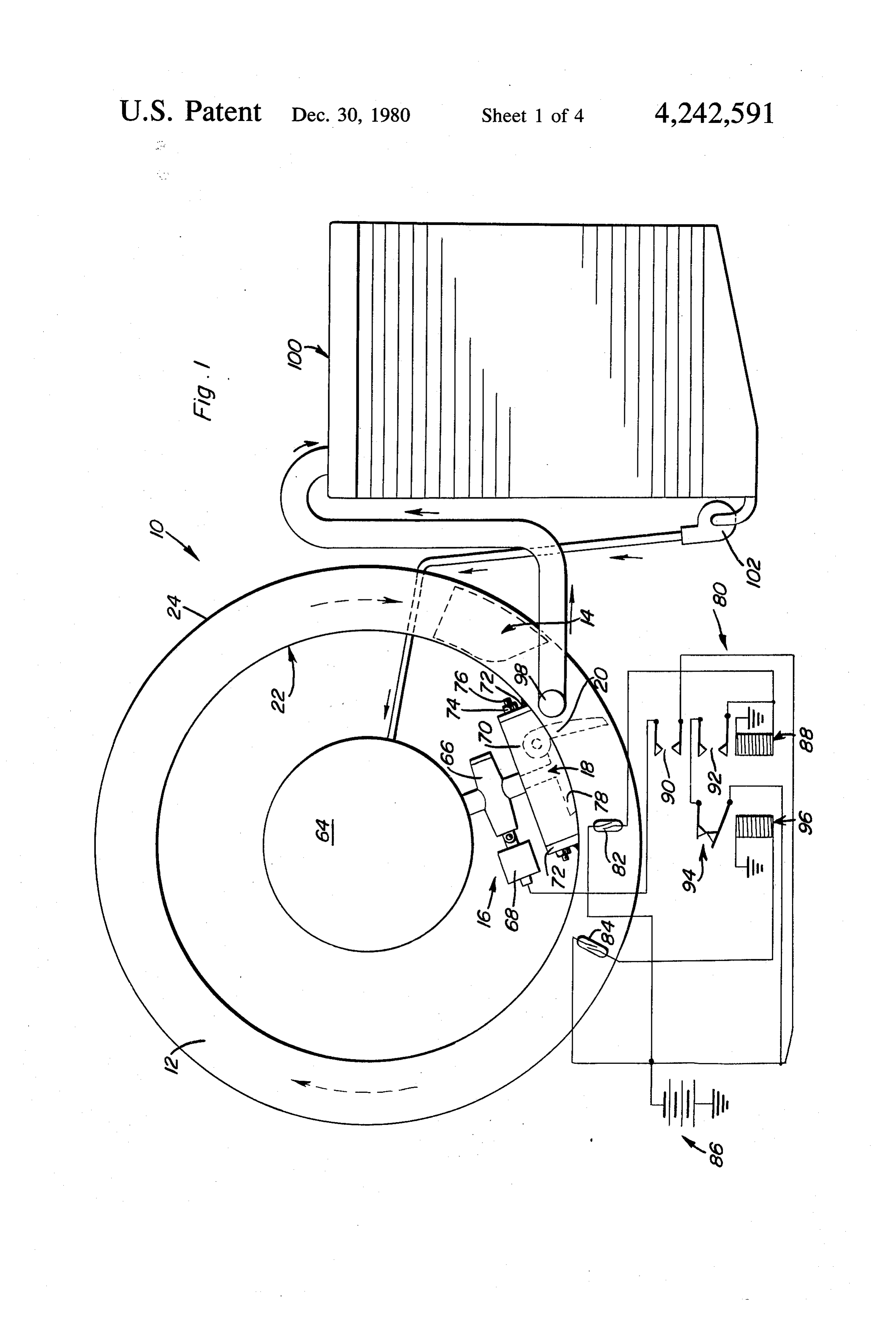
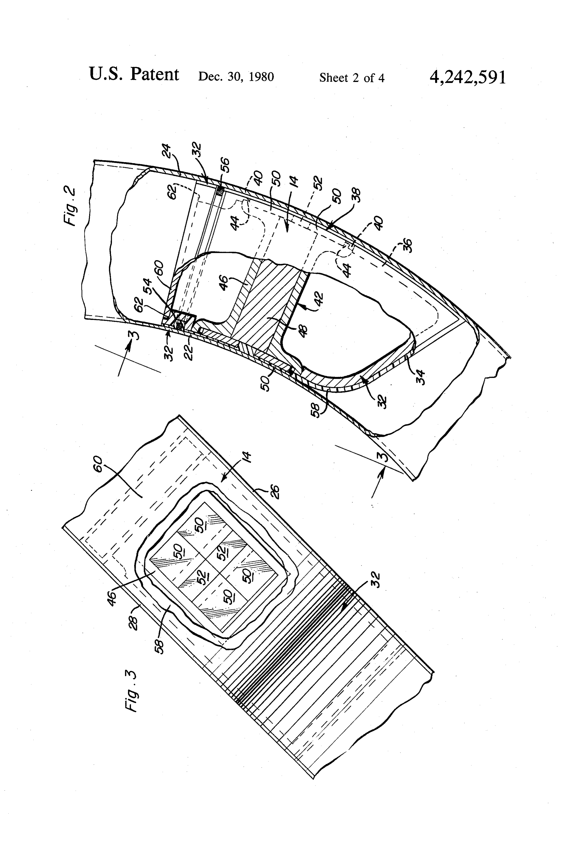
ORBITALLY ROTATNG PSTON ENGINE wherein like numerals refer to like parts throughout, BACKGROUND OF THE INVENTION BRIEF DESCRIPTION OF THE DRAWINGS 1. Field of the Invention FIG. 1 is a schematic diagram illustrating the opera This invention relates to devices for the conversion of tion of the free piston embodiment of the invention. heat energy into mechanical energy and electrical en FIG. 2 is an elevational part sectional view showing the shape of the piston and location of the magnets of ergy and especially engines which perform this trans the free piston embodiment.
formation through the use of rotating pistons. O FIG. 3 is a plan view of the piston taken substantially 2. Description of the Prior Art
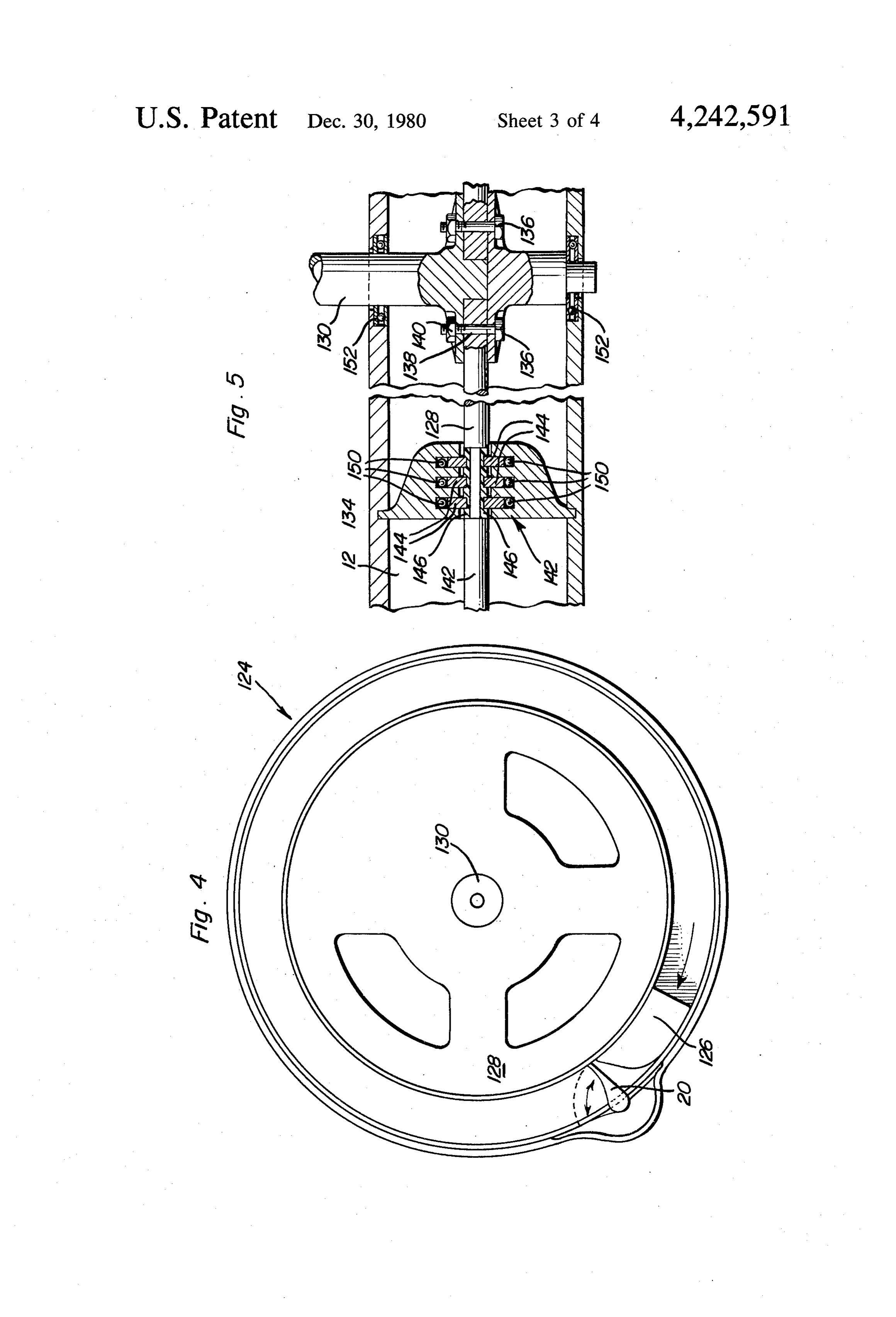
In the past, many and varied types of engines have 2. a plane passing through section line 3-3 of FIG. along been known for producing mechanical motion and transforming this motion into electrical energy. The tionFIG. 4 is a schematic view demonstrating the opera standard internal combustion engine is probably the 15 FIG. 5 isrotating of the shaft embodiment of the invention, sectional view showing the connection of most notable among these. The internal combustion the piston to the rotating shaft of the embodiment of engine is plagued with numerous deficiencies, however. FIG, 4.
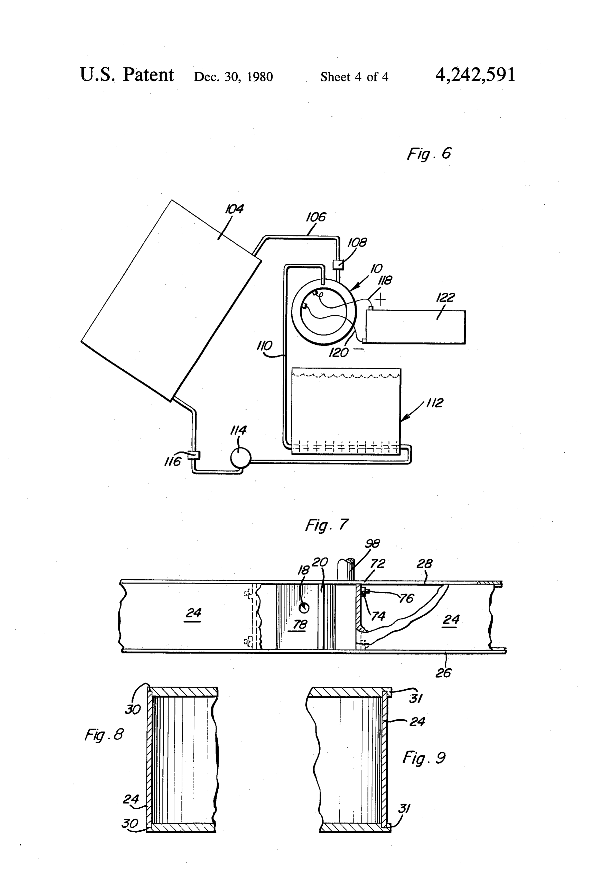
The internal combustion engine uses large amounts of FIG. 6 is a schematic representation of a solar power fossil fuel thereby rapidly depleting this precious natu version of the invention.
ral resource. Furthermore, due to the nature of the FIG. 7 shows the shutter and intake port configura confinement of the combustion of the gases in this type tion of the invention.
of engine, numerous hazardous pollutants are emitted FIG. 8 shows one wall configuration for the piston into the environment. Also, the internal combustion chamber.
engine is not amenable to use with a solar energy FIG. 9 shows an alternate wall configuration for the source. As solar energy is now coming to be seen as a 25 piston chamber.
viable source of future energy for the world, an engine is required which may efficiently convert solar energy DESCRIPTION OF THE PREFERRED into mechanical or electrical power. EMBODIMENT
The well known turbine engine is an external com Now with reference to the drawings, the rotating bustion engine which may be capable of overcoming piston engine of the invention will be clearly set forth. some of the deficiencies of an internal combustion en With particular reference to FIGS. 1-3, the free piston gine. However, this type of engine is plagued with defi embodiment of the invention, generally referred to by ciencies of its own. For example, the high operating numeral 10, will be clearly described in detail. As can be temperatures together with the high operating pressures seen in FIG. 1, the engine has a basically toroidal cham inherent in a turbine make it incompatible for use in a 35 ber 12 which is traversed by free piston 14. Power is domestic environment. supplied to the piston 14 through the valving mecha SUMMARY OF THE INVENTION nism 16 which allows entry of an expanding vapor through inlet port 18. The expanding vapor acts against
An object of my present invention is to provide an piston 14 and shutter valve 20 and thereby imparts mo engine wherein mechanical energy may be efficiently tion to the piston.
transformed into electrical energy. In one embodiment The chamber 12 is not perfectly toroidal in shape. of the invention, a free piston rotates through a circular Due to considerations of manufacturing costs, cylinder path. The piston carries with it several magnets and at 12 is given a square cross section and is constructed of least one toroidal coil is disposed to cut the flux lines of an inner circular wall 22, an outer circular wall 24 and the magnets thereby producing electrical energy with 45 two radially extending side walls 26 and 28. The side out the need for intervening mechanical linkages. walls are preferably constructed of 304 non-magnetic A further object of the present invention is to provide stainless steel or any other suitable non-ferrous metal. the engine which is run by the use of a Rankine cycle. The side walls of the cylinder constitute the main struc In this manner, the engine may use external combustion tural support of the engine. The finished thickness of the techniques thereby reducing pollution and making the 50 walls should be approximately 0.375 of an inch. The engine amenable for use with many various types of inner and outer circular walls will also be made from fuels which are commonly available. Alternatively, 304 stainless sheet metal. These walls should preferable power may be supplied to the system directly by the use have a thickness from between 0.062 and 0.118 of an of a solar panel. inch. The side walls may be connected to the circular A still further object of my present invention is to 55 walls as shown in FIG.8 or FIG. 9. In FIG. 8, it will be provide a Rankine cycle piston engine wherein the seen that outer circular wall 24 is disposed within cir piston has an extremely long stroke thereby enabling cumferentially extending notches 30. The connection the maximum expansion of the gas used in the Rankine may be maintained by the use of welding or any other cycle and thus providing an engine with a high effi suitable connection means. In FIG. 9, it will be seen that ciency. a similar connection is made except that in this case, the One still further object of the present invention is to addition of flanges 31 on the side walls provides for a provide a basic design which can incorporate a rotating more secure engagement between the walls. Again, shaft for the operation of a standard alternator or me welding or any other suitable permanent engagement chanical devices if desired. means may be employed for maintaining this connec These together with other objects and advantages 65 tion. In some uses a toroidal chamber can be substituted. which will become subsequently apparent reside in the FIGS. 3 and 4 show piston 14 in detail. The piston has details of construction and operation as more fully here a main body 32 which is preferably made from alumi inafter described and claimed, reference being had to num and may be cast or machined from bar stock. The 7 main body 32 is preferably produced having a hollow closed contacts 94 of latching relay 96. When the piston conformation to reduce the weight of the piston. The i4 passes proximity switch 84, the contacis of this body is shaped to conform with the four walls of the switch close thus energizing relay 96 and opening piston chamber and has a front sloped surface 34 which contacts 94 thus deemergizing relay 88. In this manner, is configured for making contact with the shutter valve a variable power cycle may be effected through the 20. The piston arcuate outer surface 36, which is in positioning of switches 82 and 84. contact with circular wall 24 includes an open central Located approximately 355 degrees from intake port portion 38 which contains a peripheral step 40 for ac i8 is the exhaust port 98. Exhaust port 98 is in direct cepting the outer surface of magnetic insert 42. Insert 42 communication with condenser 100. As piston 14 trav has complementary step portions 44 which co-act with 10 els under the influence of the expanding vapors from step 40 to hold the insert within the piston under centrif inlet 18, it pushes the spent vapors out of the chamber. ugal force created during the rotation of the piston. The through exhaust port 98. The spent vapors are con magnetic insert has a body 46 with a soft iron piece 48 densed in condenser 100 and the condensed freon is bonded internally thereof. On both longitudinal ends of returned via pump 102 to boiler 64. the insert, there are bonded sumarium cobalt magnets 15 In operation therefore, it will be seen that piston 14, 50 with smaller magnets 52 bonded therebetween. It is when positioned in proximity to switch 82, is forced to contemplated that a total of eight larger magnets 50 and move through the energy of the expanding vapors en the four smaller magnets 52 should be used on the pis tering the chamber 12 through inlet 18. The piston 4 ton. Other field magnet designs can also be used. traverses the chamber past switch 84 whereupon valve Toward the rear of the piston body 32, a circumferen 66 is closed thereby stopping the entry of vapors to the tially extending slot 54 is included and provides the chamber. The expanding vapors continue to push piston support surfaces for pressure seal 56. Pressure seal 56 14 through the chamber until the piston reaches exhaust seats in slot 54 and presses against the inner and outer port 98. The momentum of the piston carries it past the circular walls as well as the side walls of the chamber in exhaust port and displaces shutter valve 20. Once past order to prevent against the escape of expanding vapor 25 shutter valve 20, piston 14 again causes the closure of past the piston. The seals are teflon seals having a 20% switch 82 which forces a new supply of vapor into the glassfiber reinforcement wrapped about stainless steel chamber and closes the shutter valve 20. During the tensioning springs. Additional sealing and surfacing is next cycle of the piston, the spent vapors from the pre afforded by the use of tefion coating 58 which covers vious cycle are expelled through the exhaust 98 and into the magnets as well as the main body of the piston on all 30 condenser 100 where they are condensed and passed to four sides which contact the walls of the chamber as the boiler through pump 102 to be reheated and pres well as the forward sloped portion 34 of the piston. The ented to inlet 8 once again. Electrical energy may be rear of the piston is enclosed by rear coverplate 60 extracted from the piston by the use of a toroidal coil which is seated in a depression 62 in the rear of the (not shown) which may be wrapped about the exterior piston body and held in place by welding or any other 35 of chamber 12 in a known fashion. suitable bonding technique. At moderate piston speeds Now with reference to FIG. 6, a solar powered em lubrication is not required. bodiment of the invention will be set forth. Shown in With reference to FIG. together with FIG. 7, it will FIG. 6, a solar collector 104 takes the place of the previ be seen that the power is supplied to the system from a ously used boiler. Solar collector 104 heats the working standard boiler 64 which may be equipped to burn any 40 fluid which is passed through piping 106 and through known fossil or non-fossil fuel. The boiler 64 will be injection valve 108 to the piston chamber of engine 10. used to heat, preferably, freon F-113. This freon has a The spent vapors are removed through tubing 110 and boiling point of 117.6 F. and is missible with refrigerant condensed in condenser 112. The condensed liquid is oils which can provide lubrication to the system. The then stored in a reservoir 114 where it is drawn as heated freon under a pressure of 400 PSIG and tempera 45 needed by high pressure feed pump 116 and passed ture of 389 degrees F., enters inlet 18 through valve 66 through solar collector 104 to repeat the cycle. The which is operated by solenoid 68. Inlet valve 8 is lo electrical energy is removed through wires 118 and 120 cated in inlet manifold 70 which is bolted to flanges 72 and stored for future use as in battery 122. Water may contained on the inner periphery of the inner circular be used as the cooling fluid in condenser 112 and this wall 22 by the use of bolts 74 and studs 76. The manifold SO cooling water upon leaving the condenser may be 70 also has shutter valve 20 mounted thereon and rotat stored in a hot water heater for home use. The working able with respect thereto. The manifold 70 has a depres fluid of this system is again preferably freon. The freon sion 78 into which shutter valve 20 is displayed upon chosen may be a function of the temperature in which contact therewith by the forward sloped wall 34 of the system is to perform. For instance, freon 21, which piston 14. 55 boils at 48 degrees F. at a pressure of 200 PSIG, may be Valving mechanism 16 which includes solenoid 68 used during the colder seasons while freon 113 can be and valve 66 is operated by the control circuit generally used during the hotter seasons. In this manner, the sys labelled 80. Circuit 80 includes two proximity switches tem may be adapted to the temperature and area in 82 and 84. Proximity switch 82 controls the flow of which it is to be used and will still effectively produce current from battery 86 to solenoid control relay 88. 60 a significantly quantity of energy. Water may be the When switch 82 senses the presence of the magnets working fluid in high pressure and temp units such as mounted on piston 14, the switch closes thereby com municiple or professionally operated units. pleting a circuit from the battery through relay 88 to With reference to FIGS. 4 and 5, a second embodi ground. Normally open contacts 90 and 92 close. ment of the engine shown generally at 124 will be set Closed contacts 90 supply energy to double acting sole 65 forth. This embodiment incorporates a nonfree piston noid 68 which places valve 66 in the open position 126. Piston 126 is attached to rotor plate 128 which supplying compressed vapor to the cylinder bore. Sole rotates about and turns a central shaft 130. The mecha noid 88 is held in by current which passes to normally nism of operation including the boiler valve system and 8 shutter valve 20 are identical to those previously set sponsive to the position of said piston to initiate activa forth and will not be discussed in detail. The sole differ tion of said injection valve and a second position re ence between embodiment 124 and embodiment 10 is in sponsive switch means responsive to the position of said the attachment of the piston to the shaft 130 as shown in piston to terminate activation of said injection valve. embodiment 124. This rotating shaft 130 enables the use 4. The engine of claim 1 wherein said power removal of a standardly available generator or alternator and means includes a plurality of magnets connected to said limits the need for a toroidal coil wrapped about the piston for movement therewith and an electrical con chamber's exterior as is used and discussed in respect to ductor connected to the piston chamber, the piston and the previous embodiment. As seen in FIG. 5, rotor magnet traversing the chamber to produce electrical extension 132 is bonded to piston 126 at the rear thereof. 10 current in the conductor.
The rotor 128 extends through the inner circular wall 5. The engine of claim 2 wherein said power produc 134 and connects to shaft 130 by use of bolts 136 which ing means further includes an exhaust means for remov pass through annular slot 138 and the inner portion of ing said propellant from said chamber, a condenser for rotor 128 and are held in place by nuts 140. The inner condensing said propellant, and a heating means for peripheral wall 134 includes seal seat structure 142. The 15 heating and pressurizing said propellant, said heating seal seat structure includes three teflon seal rings 144 means being connected to said injection valve means. connected on each side of the rotor plate 128. These 6. The engine of claim 5 wherein said heating means teflon steel rings are seated in teflon seal ring seats 146 comprises a boiler.
which are bonded to the rotor. At the extreme end of 7. The engine of claim 5 wherein said heating means each teflon seal ring, is included an annular O-ring 150 20 comprises a solar panel.
which seals between the teflon seals and the inner circu 8. The engine of claim 1 wherein said power removal lar wall 134. Shaft 130 is supported and journalled by means includes a mechanical connection means me thrust bearings 152 and may be connected to any suit chanically connected to said piston through said cham able fly wheel, alternators or any other suitable energy ber wall for producing rotation of an output shaft. storing or converting devices. The bearings & walls will 25 9. The engine of claim 1 wherein said piston chamber be sealed & leakage of freon through rotor seals scav has a generally rectangular cross section and said piston enged to condenser. has four walls which contact the four walls of said The foregoing is considered as illustrative only of the chamber and a forward sloping wall for periodic principles of the invention. Further, since numerous contact with said valving means.
modifications and changes will readily occur to those 30 10. A Rankine cycle energy converting device com skilled in the art, it is not desired to limit the invention prising:
to the exact construction and operation shown and a rotating piston engine having a stationary annular described, and accordingly, all suitable modifications piston chamber with a piston disposed within the and equivalents may be resorted to, falling within the chamber;
scope of the invention. 35 a two-state refrigerant for use in the system; What is claimed as new is as follows: a heating means for heating and pressurizing said 1. An orbitally rotating free piston engine compris refrigerant;
1ng: injection means for injecting said heated, pressurized a stationary piston chamber configured in a hollow refrigerant into the chamber whereby the vaporiza annulus; 40 tion and expansion of said refrigerant forces said a piston disposed within said chamber and capable of piston through said chamber, exhaust means for orbitally traversing said chamber; removing the spent refrigerant from the said cham valving means for closing off said chamber when not ber;
in contact with said piston and opening said cham condenser means for condensing said refrigerant, said ber when contacted by said piston, said valving 45 condenser means having an output connected to means including a shutter valve which extends said injection means; and across said hollow annulus, said shutter valve being control means for controlling the injection of said pivotally connected to the chamber wall, and a propellant based on the position of said piston recess disposed in the chamber wall proximate the within said chamber, said control means including shutter valve for receiving the shutter valve when 50 a first proximity sensor for sensing the position of said piston contacts said shutter valve forcing the said piston and a second proximity sensor spaced shutter valve to pivot away from its position across from said first proximity sensor for sensing a sec said hollow annulus; ond position of said piston. energy transfer means for causing a reaction against 11. The system of claim 10 wherein said heating said valving means for imparting motion to said 55 means includes a boiler.
piston; and 12. The system of claim 10 wherein said heating power removal means for removing usable energy means includes a solar panel.
from said engine. 13. The system of claim 10 wherein said piston in 2. The engine of claim 1 wherein said energy transfer cludes at least one magnet located thereon for motion means includes a source of compressed propellant, and 60 therewith through said chamber, and an electrical con injection valve means for injecting said propellent into ductor disposed in proximity to said chamber, said mov said chamber and allowing the expansion thereof, and ing magnet causing the production of electrical current control means for activating said injection valve based within said conductor.
on the position of said piston. 14. The system of claim 13 wherein said piston is 3. The engine of claim 2 wherein said control means 65 constrained in motionk only sk by kthe ispiston chamber.
includes a first position responsive switch means re
Provenance
- Collection
- Patents citing this work
- Pages
- 8
- Method
- pdftotext (the PDF's own text layer) + pdftoppm 300dpi page scans
- Patent office record
- patents.google.com →
- Source
- Google Patents citing-documents table
- Assignee
- Harville Ronald W
- Published
- 1980-12-30
- Transcribed from
- patentimages.storage.googleapis.com →