

patent · US4131412A
Fuel ignition system having interlock protection and electronic valve leak detection
26 December 1978
Text
Page 1bibliographic recordscan →
United States Patent (19)
Matthews
54 FUEL IGNITION SYSTEM HAVING
INTERLOCKPROTECTION AND
ELECTRONIC VALVE LEAK DETECTION
(75) Inventor: Russell B. Matthews, Goshen, Ind.
(73) Assignee: Johnson Controls, Inc., Milwaukee,
Wis.
* Notice: The portion of the term of this patent subsequent to Jul. 12, 1994, has been disclaimed.
Related U.S. Application Data 63 Continuation-in-part of Ser. No. 621,670, Oct. 14, 1975,
51 Int. Cl’............................................... F23Q 9/12 52 U.S. Cl. ....................................... 431/16; 431/22;
Field of Search .................................... 431/16, 22
INTERLOCK CKT 8
3,086,583 4/1963 Reichow ................................ 431/22 3,194,296 7/1965 Brown ....... ... 431/22 3,840,322 10/1974 Cade .......... ... 43/78 4,035,134 7/1977 Matthews .. ... 431/22 4,047,878 9/1977 Matthews .............................. 431/22 Primary Examiner-Carroll B. Dority, Jr.
Agney Agent, or Firm-Emrich, Root, O'Keeffe &
A fuel ignition system of the pilot ignition type includ ing a control circuit for operating pilot and main valves of a redundant valve assembly, the control circuit hav ing control relays which provide an interlock on start up to prevent the energization of the valves under cer tain failure conditions, the control circuit including a flame sensing circuit which is operable to prevent start up of the system when a flame is provided as the result of a leak condition for the pilot valve, and to terminate an ignition cycle causing complete shut off of fuel whenever a flame is provided as the result of a leak condition for the main valve.
15 Claims, 1 Drawing Figure
Drawings
Page 2drawing sheetscan →
Page 3scan →
main valve is effected in response to the operation of a
FUEL IGNITION SYSTEMI HAVING INTERLOCK flame relay when a pilot flame is established, but only if PROTECTION AND ELECTRONIC VALVE LEAK the control relay is energized.
DETECTION While such interlock circuits guard against the
RELATED APPLICATIONS welded contact failure referred to above, it appears that the control (or flame) relay may be energized inadvert
This is a continuation-in-part application of copend antly following a failure of a solid state control device ing application Ser. No. 621,670, now U.S. Pat. No. of the electronic circuits, allowing the main valve to 4,035,134, issued July 12, 1977. As to common subject operate in the absence of a pilot flame. Also, in the matter, applicant claims the benefit of the priority date O patented systems, the flame sensing circuit is energized of said patent under 35 U.S.C. 120. in response to the operation of a control device, such as BACKGROUND OF THE INVENTION a thermostat. Thus, in the event of a leak condition for a fuel valve of the system, which permits a flame to 1. Field of the Invention remain establish after the system is deactivated, it would This invention relates to fuel ignition systems of the 15 appear that under certain failure conditions, the flame pilot ignition type and more particularly, to a control sensing circuit would be ineffective to lockout the sys circuit for use in such systems for providing an interlock tem before the control relay operated. on start-up under certain failure conditions. In the U.S. Pat. No. 3,840,322 to Philip J. Cade, there 2. Description of the Prior Art is disclosed an automatic fuel ignition control system In known fuel ignition systems of the pilot ignition 20 which effects lock out of the system whenever a flame type, a pilot valve is operated in response to the closure is provided at a burner apparatus before the end of an of thermostatically controlled contacts to supply fuel to ignition timing interval. However, the system will also a pilot outlet for ignition by a suitable igniter to establish be locked out following a pilot flame. A pilot flame sensing circuit detects the cycle or in the event of aa loss of flame during a heating pilot flame and effects the energization of a main valve 25 very short duration, wherein thevoltage line pilot interruption of a frame is not extin which supplies fuel to a main burner apparatus for igni guished before power is restored.
tion by the pilot flame. In my U.S. Pat. Application Ser. No. 621,670, filed Typically, the operation of the main valve is con Oct. 14, 1975 and now U.S. Pat. No. 4,035,134, there is trolled by a relay of the flame sensing circuit which has disclosed a proven pilot fuel ignition system including a normally open contacts connected in the energizing control arrangement path for the main valve to maintain the main valve start-up to prevent thewhich provides an interlock on energization of fuel valves of the deenergized until a pilot flame is established. When a system under certain failure conditions. The control pilot flame is established, the flame sensing circuit ener arrangement also detects a leak condition for pilot and gizes the relay which closes its contacts to connect the main valves of the system, effecting shut down of the main valve to an energizing circuit to permit the main 35 system for a leak condition for either valve, but permit valve to operate.
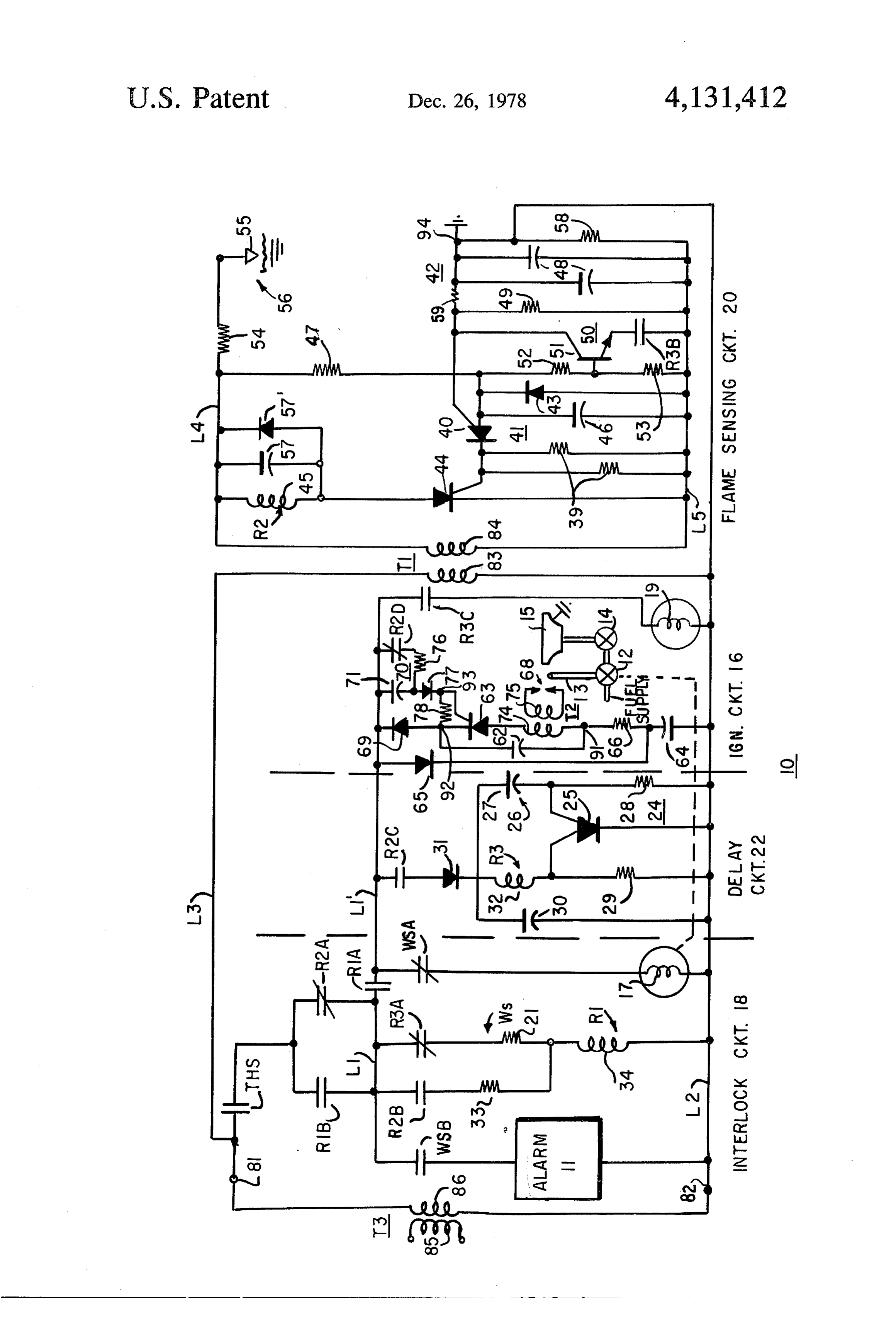
After the heating demand has been met, the thermo ting recycling of the system following a momentary statically controlled contacts open to effect deenergiza power loss or a flame out condition. The control arrangement includes a delay circuit tion of the fuel valves and cause the flame to be extin guished. The flame sensing circuit responsively causes which effects operation of a control relay to allow ener the relay to be deemergized, opening its contacts to gization of the pilot valve and a flame sensing circuit disconnect the main valve from the energizing circuit in ater a first delay following the activation of the system. preparation for the next heating cycle. However, If a flame is established at the time the flame sensing should the relay contacts which control the energiza circuit is energized, the flame sensing circuit causes the tion of the main valve become welded together follow 45 by system to be locked out. Such timing control is afforded a timing circuit of the flame sensing circuit which ing a successful ignition cycle, then, when the relay is requires deenergized, the main valve remains connected to the sensing circuit absence of a flame for a time after the flame energizing circuit and will be energized when the ther flame sensing circuit is energized before a flame relay of the mostatically controlled contacts close in response to the is allowed to operate. Under nor call for heat, even though a pilot flame is not estab 50 mal conditions, the delay circuit is disabled under the lished. Similarly, the main valve will also be connected control of the flame relay and effects energization of the to the energizing circuit for a circuit failure which per main valve after a second delay interval after the pilot mits the relay of the flame sensing circuit to be ener flame is established. The flame sensing circuit prevents gized in the absence of a pilot flame. For such failure operation of the main valve if a main burner flame is conditions, both the pilot valve and the main valve will 55 sensed during the second delay interval. An interlock be energized when the thermostatically controlled circuit prevents enabling of the delay circuit and the contacts close, permitting fuel to emanate from the pilot control relay at start up for certain failure conditions, outlet and the main burner, an undesireable condition. including welded contacts of the flame relay. Various interlock arrangements have been proposed SUMMARY OF THE INVENTION in the prior art as exemplified by the U.S. Pat. Nos. 60 3,449,055 to L.C. Blackett, 3,644,074 to P.J. Cade and The present invention has provided a control circuit 3,709,783 to J.S. Warren, in which the energization of for use in a fuel ignition system of the pilot ignition type the fuel valves of the system is dependent upon the which provides an interlock on start-up to preventener sequential operation of relays. In the systems disclosed gization of fuel valves of the system under certain fail in the patents referenced above, the energization of the 65 ure conditions. The system includes a pilot valve opera pilot valve is effected in response to the operation of a ble when energized to supply fuel to a pilot outlet for control relay which can be energized only if the flame ignition to establish a pilot flame, a main valve operable relay is deemergized. Thereafter, the energization of the when energized to supply fuel to a burner apparatus for 4 ignition by the pilot flame, and a control circuit which DESCRIPTION OF THE DRAWING controls the operation of the fuel valves
The control circuit includes interlock means includ The single FIGURE is a schematic circuit diagram ing first switching means operable when enabled to for a control circuit provided by the present invention for use in a fuel ignition control system of the pilot energize the pilot valve, flame sensing means for caus ignition ing a second switching means to be enabled whenever a type.
pilot flame is provided, and delay means responsive to DESCRIPTION OF A PREFERRED the second switching means to effect the energization of EMBODIMENT the main valve at the end of a time interval, the flame 10 sensing means preventing the energization of the main matic Referring to the drawing, there is illustrated a sche valve and causing the pilot valve to be deenergized if a circuit diagram for a fuel ignition control circuit flame is provided at the burner apparatus during the 10 provided by the present invention. The control cir time interval, indicative of a leak condition for the main cuit 10 is described with reference to an application in a valve. Also, the flame sensing means controls the sec 15 aheating system of the pilot ignition type which includes ond switching means to prevent the first switching and the main 12 pilot valve and a main valve 14. The pilot valve 12 valve 14 may comprise a redundant valve means from being enabled, locking out the system, if a assembly in which fuel is supplied to the main valve 14 pilot flame is provided at the onset of the trail for igni through the pilot valve 12, and thus only when the pilot tion interval, indicative of a leak condition for the pilot valve 12 is operated. One redundant valve structure valve. 20 suitable for this application is disclosed in my U.S. pa More specifically, in accordance with a disclosed tent application Ser. No. 630,166, which was filed on embodiment, the pilot valve and the main valve com Nov. 10, 1975 and now U.S. Pat. No. 4,044,794. prise a redundant valve structure in which fuel is sup The pilot valve 12 is operable to supply fuel to an plied to the main valve through the pilot valve only inlet of the main valve 14 and to a pilot outlet 13 for when the pilot valve is operated. The pilot valve is 25 ignition by sparks provided by an igniter circuit 16 to energized by the first switching means of the interlock establish a pilot flame in the proximity of a burner appa means, which in turn is energized over a first circuit the ratus 15. The main valve 14 is operable to supply fuel to path in response to an activate means, such as a thermo main burner apparatus 15 for ignition by the pilot statically controlled switch, and operates to complete a 30 flame. Due to the redundant valve structure, fuel can be second circuit path for energizing the pilot valve. The supplied to the burner apparatus 15 only when both the first switching means is energized over the first circuit pilot valve 12 and the main valve 14 are operated. The pilot valve 12 and the igniter circuit 16 are ener path during a trial for ignition period defined by a time gized by an interlock circuit 18 which includes a first out device of the interlock means. The timeout device is switching device or actuator, embodied as a relay R1, operable to deenergize the pilot valve of the redundant 35 which is operable valve assembly if a pilot flame fails to be established solenoid 17 of the to complete an energizing path for a pilot valve 12 and the igniter circuit during the trial for ignition interval, providing 100% 16. The relay R1 is energized during a trial for ignition shut off of fuel. The time-out device is initially ener period initiated by the closing of thermostatically con gized over the first circuit path, and if such path is trolled switch contacts THS in response to a request for interrupted at start-up, the system cannot be activated. heat. The interlock circuit 18 includes a timeout device, When a pilot flame is established, the flame sensing embodied as a warp switch WS, which defines the trial means, which is continuously energized, responds to the for ignition period and is operable to deemergize the flame to enable the second switching means which con pilot valve 12 of the redundant valve assembly if a pilot nects the delay means to the second circuit path for flame fails to be established during the trial for ignition energization. The delay means includes third switching 45 period, thereby terminating the ignition cycle and pro means which is operable when enabled to connect the viding 100% shut off of fuel to the burner apparatus 15. main valve to the second circuit path for energization, The warp switch WS also enables an alarm device 11 to and an enabling means which delays the enabling of the indicate that the system is locked out. third switching means for a predetermined time after 50 The main valve 14 is energized under the control of a the delay means is energized. If a flame is provided at flame sensing circuit 20 and a delay circuit 22. When a the burner apparatus during such delay interval, as due pilot flame is established, the flame sensing circuit 20 to a leak condition for the main valve, for example, the responds to the flame to operate an associated second ignition cycle is terminated before the main valve is whichswitching device or actuator, embodied as a relay R2, allowed to operate, and the system is locked out. completes an energizing path for the delay cir 55 cuit 22. The delay circuit 22 includes a third switching
In accordance with the invention, the switching means which may comprise relays or some other device or actuator, embodied as a relay R3, which is operable to complete an energizing path for the main contact operating switch device, afford a contact inter valve 14. The delay circuit 22 also includes an enabling lock protection which guards against unsafe failures circuit 24, which delays the enabling of relay R3 for a including component failures, welded contacts, or a predetermined time after the delay circuit 22 is ener leak condition for either one of the valves. If for any gized. If a flame is provided at the burner apparatus 15 reason the first switching means fails to operate before during such delay interval, as due to a leak condition for either the second or third switching means operates, a the main valve 14, the ignition cycle is terminated be start-up of an ignition cycle is prevented, and both fore the main valve 14 is allowed to operate, and the valves are maintained deenergized. Also, once an igni 65 system is locked out.
tion cycle is started, the system may be locked out, In accordance with the invention, relays R1-R3 af. under certain failure conditions including a leak condi ford a contact interlock protection which guards tion for the main valve. against unsafe failures including component failures, 5 welded relay contacts, or a leak condition for either one spaced relationship with the burner apparatus 15 defin of the valves. If for any reason relay R1 fails to operate ing a gap 56.
before relays R2 or R3 operate, a start-up of an ignition When fuel supplied to the pilot outlet or main burner cycle is prevented, and both the pilot valve and the apparatus is ignited, the flame bridges the gap 56, estab main valve are maintained deenergized. Also, once an 5 lishing a charging path for the capacitors 48, permitting ignition cycle is started, the system may be locked out, the capacitors 48 to charge while capacitor 46 is charg under the control of the warp switch WS, in the event ing. Although capacitor 46 charges at a faster rate, the of certain failure conditions including a leak condition charging or capacitors 48 raises the potential at the gate for the main valve 14. of the PUT device 40 so that a longer time is now re More specifically, referring to the interlock circuit O quired before the potential at the anode exceeds the 18, the interlock relay R1 and a heater element 21 of the potential at the gate by +0.6 volts. Thus, when the warp switch WS are energized over a circuit path charged PUT device 40 is enabled, the capacitor 46 has been which includes normally closed contacts R2A and R3A to a value which provides sufficient discharge of relays R2 and R3, respectively. Thus, relay R1 and 15 current to enable the SCR device 44, causing the relay the warp switch heater 21 can be initially energized R2Ittois be energized.
pointed out that since the flame sensing circuit 20 only when relays R2 and R3 are deenergized. When is continuously energized, relay R1 closes contacts R1A to complete an ever a flame is energized, provided relay R2 is operated when at the pilot outlet 13. Thus, energizing path for the pilot valve solenoid 17 over when the control circuit is deactivated by the opening normally closed contacts WSA of the warp switch WS, permitting the pilot valve 12 to open to supply fuel to 20 of contacts THS at the end of each heating cycle, relay the pilot outlet 13. The igniter circuit 16 is also ener R2 willofremain operated with contacts R2A open in the gized to provide sparks for igniting the pilot fuel. Relay event a leak condition for the pilot valve 12 which R1 also closes contacts R1B to prepare a holding path permits a flame to remain established at the pilot outlet when the pilot valve is deemergized. Accordingly, when to permit the relay R1 and the warp switch heater 21 to contacts THS close on the next call for heat, the ener be maintained energized when relay R2 operates to 25 gizing path for relay R1 is interrupted and the system open contacts R2A, contacts RIB being connected in cannot restart.
shunt with contacts R2A. The flame sensing circuit 20 further includes an over Relay R2 is operated under the control of the flame signal clamping circuit 50, including transistor 51 which sensing circuit 20 when a pilot flame is established, to 30 is normally disabled by normally open contacts R3B of open contacts R2A and to close contacts R2B, which relay R3. Whenever a large flame is provided at the complete the holding path for relay R1, the warp switch main burner apparatus 15 before relay R3 operates, heater 21 being maintained energized over normally indicative of a leak condition for the main valve 14, the closed contacts R3A of relay R3, which is deemergized oversignal clamping circuit 50 causes the PUT device at this time. Relay R2 also closes contacts R2C to ener 35 40 to be maintained cutoff, causing deenergization of gize the delay circuit 22 and opens contacts R2D to the relay R2 and allowing the warp switch WS to effect disable the igniter circuit 16. the shut down of the system. The flame sensing circuit 20 includes a controlled As indicated above, when relay R2 operates, its switching device, embodied as a programmable uni contacts R2C close to enable the delay circuit 22 and its junction transistor 40, which together with associated 40 contacts R2D open to disable the igniter circuit 16. timing networks 41 and 42, effect the enabling of a Briefly, as described in more detail hereinafter, the further controlled switching device, embodied as a igniter circuit 16 is of the capacitor discharge type, silicon controlled rectifier 44, which controls the opera having a capacitor. 62 which is periodically charged by tion of relay R2. The timing, or anode control network an AC signal supplied over normally closed contacts 41, which includes a timing capacitor 46, determines the 45 R2D of relay R2, and a controlled switching device, potential at the anode electrode of the PUT device 40. embodied as a silicon controlled rectifier 63, which is The timing, or gate control network 42, which includes operable to cause the capacitor 62 to discharge over an redundant timing capacitors 48, determines the poten ignition transformer T2 to effect the generation of tial at the gate of the PUT device 40. sparks between ignition electrodes 68. The ignition The PUT device 40 is enabled whenever the potential SO electrodes 68 are located adjacent to the pilot outlet 13 at its anode exceeds the potential at its gate by +0.6 to ignite the pilot fuel emanating therefrom. volts. Capacitor 46, which determines the potential at When relay R2 operates to open contacts R2D, the the anode of the PUT device 40, is periodically charged capacitor 62 is permitted to be charged periodically for over a resistor 47 by an AC signal which is continuously a time determined by a timing network 70 including a supplied to the flame sensing circuit 20 over an isolation 55 timing capacitor 71, whereby the igniter circuit 16 con transformer T1. In the absence of a flame, capacitors 48 tinues to provide sparks for a time after relay R2 oper remain essentially uncharged, such that the enabling of ates.
the PUT device 40 is effectively controlled by the Referring to the delay circuit 22, the enabling circuit charging of capacitor 46. When the PUT device 40 is 24 includes a controlled switching device, embodied as enabled, capacitor 46 discharges into the gate of the 60 a programmable unijunction transistor 25, which is SCR device 44. However, in the absence of a flame, the operable when eanbled to complete an energizing path discharge current is insufficient to enable the SCR de for relay R3. The enabling circuit 24 further includes a vice 44, and the relay R2 remains deemergized. timing network 26 including a capacitor 27, which con For the purpose of permitting relay R2 to be ener trols the enabling of the PUT device 25. The capacitor gized when a flame is established, the flame sensing 65 27 is permitted to charge in response to activation of the circuit 20 further includes a flame sensor, embodied as a delay circuit 22 following the closing of contacts R2C sensing electrode 55, which is located in the proximity of relay R2 and, after a delay established by the charg of the burner apparatus 15 and the pilot outlet 13 in a ing time of capacitor 27, the PUT device 25 is enabled, 6 causing relay R3 to operate to close contacts R3C, causes relay R2 to be operated in the absence of a flame, effecting the enabling of the main valve 14. Also, then contacts R2A will remain open, preventing start contacts R3A open to deemergize the warp switch up on the next call for heat. Also a leak condition for the heater 21 and contacts R3B close enabling the over-sig main valve 14 will permit fuel to be supplied to the main nal clamping circuit 50 of the flame sensing circuit 20. burner 15 before the main valve is energized. Under Contacts R3A of relay R3 permit the warp switch such conditions the fuel will be ignited by the pilot heater 21 to remain energized from the time that flame causing the oversignal clamping circuit 50 to contacts THS close until after the delay establishing by effect the disabling of relay R2, preventing the enabling the enabling circuit 24 at which time relay R3 operates of relay R3. Accordingly, the warp switch WS will time to energize the main valve 14. Thus, in the event of an 10 out, deactivating the control circuit 10 with the pilot unsafe failure which prevents the operation of the relay valve 12 deemergized, providing 100% shut off of fuel. R3 before the heating time of the warp switch heater 21, DETAILED DESCRIPTION the warp switch WS operates to open contacts WSA, deenergizing the pilot valve 12, effecting 100% shut off Considering the fuel ignition control circuit 10 in of fuel supply to the burner and causing the system to be 15 more detail, the circuit 10 has a pair of input terminals locked out. The warp switch WS also closes contacts 81 and 82 which are connectable to a 24 VAC source WSB to enable the alarm device 11 to indicate the lock for supplying power to the circuit 10. Terminal 81 is out condition for the system. connected over normally open contacts THS and over Operation normally closed contacts R2A of relay R2 to a conduc 20 tor L1, and terminal 82 is connected to a conductor L2.
Briefly, in operation, when the thermostatically con The 24 VAC energizing signal may be supplied to the trolled contacts THS close in response to a request for control circuit 10 over a transformer T3, having a pri heat, the warp switch heater 21 and the relay R1 are mary winding 85 connected to a source of power and a energized over the normally closed contacts R2A annd secondary winding 86 connected across terminals 81 R3A of respective relays R2 and R3. The energization 25 and 82.
of the warp switch heater 21 permits the system to be Referring to the interlock circuit 18, the heater ele maintained activated for a trial for ignition period de ment 21 of the warp switch WS and an operate coil 34 fined by the heating time of the warp switch heater 21. of relay R1 are connected in series between conductors Relay R1 operates to close contacts R1B to prepare a L1 and L2 over normally closed contacts R3A of relay holding path for the relay R1 and the warp switch 30 R3 for energization in response to the closing of heater 21, and to close contacts R1A to complete an contacts THS and whenever relays R1 and R3 are dis energizing path for the pilot valve 12 which operates to abled. Relay R1 has normally open contacts R1B con supply fuel to the pilot outlet 13. The igniter circuit 16 nected in a shunt path with contacts R2A to prepare a is also energized to generate sparks for igniting the fuel holding path for relay R1 when relay R2 operates to supplied to the pilot outlet 13. 35 open contacts R2A. Relay R1 also closes contacts R1A When a pilot flame is established during the trial for to extend power to a conductor L1' to permit energiza ignition period, the flame sensing circuit 20 causes the tion of the pilot valve 12, the delay circuit 22 and the relay R2 to operate to close contacts R2C to energize igniter circuit 16.
the delay circuit 22 and to open contacts R2D to disable To operate coil 17 of the pilot valve 12 is connected the igniter circuit 16. Relay R2 also opens contacts R2A over normally closed contacts WSA of the warp switch interrupting the energizing path for the relay R1 and WS between conductors L1' and L2 and is energized closes contacts R2B to complete a holding path for whenever contacts R1A close, permitting the pilot relay R1. valve 12 to operate to supply fuel to the pilot outlet 13 After the time delay established by the delay circuit and to the inlet of the main valve 14. The warp switch 22, relay R3 is energized closing contacts R3C to permit 45 WS also has normally open contacts WSB connected in the main valve 14 to operate, and opening contacts R3A series with the alarm device 11 between conductors Li to deemergize the warp switch heater 21. When the and L2.
heating demand has been met and contacts THS open, To operate coil 19 of the main valve 14 is connected relays R1 and R3 and deenergized and the fuel valves over normally open contacts R3C of relay R3 between drop out, interrupting the supply of fuel to the burner 50 conductors L1 and L2 and is energized when relay R3 and the pilot outlet, causing the flame to be extin operates to operate the main valve 14, supplying fuel to guished. The flame sensing circuit 20 responds to the the main burner apparatus 15 for ignition by the pilot loss of flame to deenergize relay R1 which releases flame.
opening contacts R1A, and the circuit 10 is ready for Considering the delay circuit 22, the PUT device 25 the next heating cycle. 55 has an anode control network including the operate coil If a pilot flame fails to be established during the trial 32 of relay R3 and a resistor 29, which serve as a voltage for ignition period, the warp switch WS operates to divider circuit to establish a potential at the anode of the open contacts WSA deenergizing the pilot valve 12 PUT device 25 when contacts R2C close to extend AC thereby interrupting the supply of fuel to the pilot outlet power from conductor L1 to the delay circuit 22. The 13 as well as to the main valve 14, causing the system to operate coil 32 and resistor 29 are connected between become locked out. The warp switch WS also closes conductors L1' and L2 in a series circuit with normally contacts WSB to enable the alarm device 11 to indicate open contacts R2C and a diode 31, which extends from that the system is locked out. conductor L1 over contacts R2C, diode 31, and the If relay R2 remains operated following the deactiva winding 32 to the anode of the PUT device 25, and over tion of the system, such as due to a leak condition for 65 resistor 29 to conductor L2. A capacitor 30 is connected the pilot valve 12 which permits a flame to remain es in parallel with winding 32 and resistor 29. tablished when the pilot valve 12 is deenergized, or for The PUT device 25 has a gate control network in a malfunction of the flame sensing circuit 20 which cluding capacitor 27 and resistor 28 which together 7 with diode 31 form a unidirectional series charging path The flame sensing circuit is continuously energized for capacitor 27 which extends from conductor L1' by an AC signal supplied to conductors L4 and L5 over over contacts R2C, diode 31, capacitor 27 and resistor transformer T1. The transformer T1 has a primary 28 to conductor L2. The junction of capacitor 27 and winding 83 having one end connected over a conductor resistor 28 is connected to the gate of the PUT device L3 to terminal 81, and having its other end connected to 25. The cathode of the PUT device 25 is connected conductor L2. The transformer T1 has a secondary directly to conductor L2, and thus, the PUT device 25 winding 84 connected between conductors L4 and L5. has its anode-cathode circuit connected in series with The anode control network 41 for the PUT device 40 the operate coil 32 of relay R3 and diode 31 between includes capacitor 46 and a resistor 47 which are con conductors L1' and L2 and is operable when enabled to 10 nected in series between conductors LA and L5, provid effect the energization of the relay R3. When energized, ing a charging path for the capacitor 46. The anode of relay R3 closes contacts R3C to energise the main valve the PUT device 40 is connected to the junction of resis 14 and opens contacts R3A to deemergize the wrap main tor 47 and capacitor 46. A diode 43 which is connected vlave switch heater 21. Relay R3 also closes contacts in parallel with capacitor 46, provides a bypass path for R3B to enable the over signal clamping circuit 50. 15 capacitor 46 during negative half cycles of the AC The PUT device 25 is enabled when the potential at signal.
its anode exceeds the potential at its gate by +0.6 volts. The gate control network 42 includes capacitors 48 Thus, when capacitor 27 has charged to a value that and resistors 58, 49 and 59. Resistor 49 is connected causes the potential at the gate of the PUT device 25 to between the gate of the PUT device 40 and conductor be 0.6 volts less than the potential at the anode of the 20 L5, and resistor 59 is connected between the gate of the PUT device 25, the PUT device 25 is enabled, energiz PUT device 40 and the ground point for the control ing the relay R3. Thereafter, the PUT device 25 is en circuit 10 at point 94, which is also connected to con abled during each positive half cycle of the AC signal, ductor L2. Capacitors 48 are connected in parallel be the relay R3 being maintained energized during the tween point 94 annd conductor L5 and a bleeder resis negative half cycles by capacitor 30. 25 tor 58 is connected in parallel with capacitors 48. Referring to the igniter circuit 16, capacitor 62 is The flame sensing electrode 55 and resistor 54 form a charged and then discharged over the primary winding portion of the gate control network 42 for the PUT 74 of the ignition transformer T2 during alternate half device 40. The sensing electrode 55 is connected over cycles of the AC signal, to provide sparks between a resistor 54 to conductor LA, with the electrode 55 being pair of ignition electrodes 68 which are connected to 30 positioned in a spaced relationship with the ground the secondary winding of the transformer T2. The igni reference point 94 for the conrol circuit 10, normally tion electrodes 68 are disposed adjacent to the pilot providing a high resistance path, virtually an open cir outlet 71 is a spaced relationship, providing a gap there cuit, between conductor L4 and the reference point 94. between. As indicated above, the ground reference point 94 may The igniter circuit 16 includes a voltage doubler cir 35 be a metallic ground provided by the burner apparatus cuit including capacitor 64 which supplies a voltage to 15.
capacitor 62, enabling the capacitor 62 to be charged to The sensing electrode 55 is located adjacent to the approximately twice the line voltage supplied over pilot outlet 13 and one end of the burner15 in the region conductors L1 and L2. Capacitor 64 has a charging in which a flame is to be provided such that either a path which extends from conductor L1 over a diode 65 40 pilot or main burner flame bridges the gap 56 between and the capacitor 64 to conductor L2. Capacitor 64 is the electrode 55 and the reference point 94, thereby charged when conductor L1' is positive relative to lowering the resistance of the circuit path including conductor L2 during positive half cycles of the AC line resistor 54 over the electrode 55 between conductor LA signal. and the reference point 94 whenever a flame is estab Capacitor 62 charges during negative half cycles of lished. Thus, whenever a flame bridges the gap 55, the the AC line signal, that is when conductor L2 is positive high resistance charging path is provided for capacitors with respect to conductor L1', over a path which ex 48, allowing the capacitors 48 to charge. tends from conductor L2 over capacitor 64 and a resis The cathode of the PUT device 40 is connected to the tor 66 to one side of capacitor 62 at point 91, and from gate of the SCR device 44 and over redundant resistors the other side of the capacitor 62 at point 92 over a 50 39 to conductor L5. Thus, whenever the PUT device 40 diode 69 to conductor L1'. - is rendered conductive, a discharge pathis provided for The SCR device 63 has its anode connected to con capacitor 46 over the anode-cathode circuit of the PUT ductor L2 over the primary winding 74 of transformer device 40 to the gate of the SCR device 44. T2, resistor 66, and capacitor 64, and its cathode con The PUT device 40 is rendered conductive whenever nected to conductor L1' over diode 69. When relay R2 55 the potential at its anode exceeds the potential at its gate is deemergized, a gate control circuit is provided for the by +0.6 volts, as determined by the action of networks SCR device 63 over normally closed contacts R2D of 41 and 42. For the condition where a pilot flame is not relay R2, and resistor 76, diode 77, and resistor 78 established, the PUT device 40 conducts early in the which are connected between conductor L1 and point positive half cycles of the AC signal and before capaci 92. Capacitor 71 of the timing network70 is connecgted 60 tor 46 is charged to a value sufficient to effect enabling in shunt with contacts R2D and resistor 76 to provide of the SCR device 44. When a pilot flame is established, an alternate gate control circuit for the SCR device 63 the PUT device 40 conducts at a later time during the when relay R2 is operated. positive half cycles when the capacitor 46 is charged to The gate of the SCR device 63 is connected to the a value which is sufficient to render the SCR device 44 junction of the cathode of diode 77 and resistor 78 at 65 conductive.
point 93 to permit the SCR device 63 to conduct when The SCR device 44, which controls the energization ever the potential at point 93 exceeds the gate threshold of the relay R2, has its anode connected to one side of of the SCR device 63. the operate winding 45 of the relay R2, the other side of 8 which is connected to conductor LA. The cathode of contacts R1B close to prepare a holding path for relay the SCR device 44 is connected to conductor L5 so that R1 in shunt with contacts R2A. when the SCR device 44 is enabled, the operate wind With reference to the igniter circuit 16, when line L1" ing 45 of relay R2 is connected between conductors L4 is positive relative to line L2, capacitor 64 is charged and L5, permitting the relay to operate. 5 over diode 65 to a voltage of approximately 37 volts, The PUT device 40, which controls the enabling of When line L2 becomes positive relative to line L1 the SCR device 44, is pulsed into operation, providing during the next negative half cycle of the AC line sig an enabling pulse for SCR device 44 for each cycle of nal, capacitor 62 is charged over capacitor 64, resistor the AC signal during the trial for ignition interval. Dur 66 and diode 69, with the charge on capacitor 64 being ing the portion of the AC cycle when the SCR device 10 transferred to capacitor 62, such that capacitor 62 is 44 is non-conducting, the relay R2 is maintained ener charged to approximately 74 volts. During the next half gized by capacitor 57 and free-wheeling diode 57 cycle when line L1' is again positive relative to line L2 which are connected in parallel with the operate wind and the AC signal begins to decrease from its maximum ing 45 of relay R2. value, the voltage on capacitor 62 is greater than the Considering the over-signal clamping circuit 50, tran 15 supply voltage, permitting current to flow from the sistor 51 is operable when enabled to limit the voltage positive side of the capacitor 62 at point 91 through swing at the gate of the PUT device 40 to a predeter resistor 66, capacitor 64, the secondary winding 86 of mined value whenever a flame is provided at the burner the input transformer T3, and over contacts R2D, resis 15. The base of transistor 51 is connected to the junction tor 76, diode 77 and resistor 78 to the other side of of resistors 52 and 53, which are serially connected from 20 capacitor 62, establishing a positive voltage at the gate the anode of the PUT device 40 to conductor L5, form of the SCR device 63 which then conducts. ing a voltage divider at the base of transistor 51, with Capacitor 62 then discharges over the primary wind the base potential being determined by the charging of ing 74 of the transformer T2 and the SCR device 63, inducing a voltage in the secondary winding 75 of the capacitor 46. Transistor 51 has its collector-emitter 25 transformer circuit connected between the gate of the PUT device an ignition spark. T2, activating the electrodes 68 to generate 40 and conductor L5 over normally open contacts R3B The igniter circuit 16 continues to of relay R3. Whenever relay R3 is operated, then when operate in the manner described above, providing sparks until the relay R2 is operated in response to the the base-emitter turnon potential is exceeded, the tran flame sensing circuit when the fuel is ignited. sistor 51 conducts, clamping the gate to PUT device 40 30 When to the potential on conductor L5. The action of the capacitor relay 62 is
R2 operates and opens contacts R2D, charged and discharged, initially, over over-signal clamping circuit 50 prevents pre-mature the timing capacitor firing of the PUT device 40 when a main burner flame capacitor 62 becomes71.greater That is, when the voltage on bridges the gap 56, which would otherwise result in the during the positive half cyclesthan the supply voltage of the AC line signal, deenergization of relay R2. 35 current flows from the positive side of the capacitor 62 Relays R2 and R3 are double-pole, double-throw through relays. For relay R2, contacts R2A and R2B employ a ing 84 ofresistor 66, capacitor 64, the secondary wind common armature of the relay such that whenever resistor 78 to the other T3, transformer side capacitor 71, diode 77 and of capacitor 62, providing a contact R2A is closed, contact R2B is open. Also, turnon voltage for SCR device 63 for permitting capaci should contact R2B become welded, contact R2A can tor 62 to discharge over the ignition transformer T2 to not reclose thereby preventing energization of the inter generate a spark. The sparking continues until capacitor lock circuit 18 on the next call for heat. 71 becomes fully charged at which time current flow In relay R3, contacts R3A and R3C employ a com ceases and the SCR device 63 is not triggered, mon armature such that when contact R3A is closed, further spark generation. In one embodiment,inhibiting contact R3C is open. If contact R3C becomes welded, 45 ponent values were selected to allow the igniterthecircuit com contact R3A cannot reclose thereby preventing energi 16 to provide sparks for a period often seconds after the zation of the interlock circuit 18 on the next call for operation of relay R2.
heat. When power is applied to the flame sensing circuit 20, Operation and in the absence of a flame, then when conductor LA
When a 24VAC power signal is applied to terminals starts to swing positive, current flows from conductor
LA over resistor 47 and capacitor 46, charging the ca 81 and 82 of the control circuit 10, the flame sensing pacitor 46. Capacitor 46 charges during each postive circuit 20 is energized over transformer T1. When half cycle of the AC signal, providing an increasing contacts THS are open, and in the absence of a flame at potential at the anode of the PUT device 40. In the the pilot outlet or the main burner, relays R1-R3 are 55 absence of a pilot flame, capacitors 48 remain dis unoperated and the valves are deemergized. charged, and the PUT device 40 conducts early in the When contacts THS close in response to a request for positive half cycles of the AC signal and before capaci heat, the 24VAC signal is applied to conductors L1 and tor 46 has charged to a value sufficient to trigger the L2 over normally closed contacts R2A of relay R2 and SCR device 44 into conduction. Thus, relay R2 is main since contacts R3A are closed, heater 21 of the warp tained unoperated. If a flame fails to become established switch WS is energized, initiating a trial for ignition during the trial for ignition interval, the warp switch interval. The interval, typically 15 to 20 seconds, is WS deemergizes the pilot valve 12 locking out the sys defined by the heating time of the warp switch heater tem, and enables the alarm device 11. 21. Also, relay R1 operates closing contacts R1A, ener When a pilot flame is established before the warp gizing the operate coil 17 of the pilot valve 12 of the 65 switch WS operates, then during the next positive half redundant valve assembly, which opens to supply fuel cycle of the AC signal applied between conductors LA to an inlet of the main valve 14 and to the pilot burner and L5, when conductor LA swings positive, current 13. The igniter circuit 16 is also energized. Further, flows from conductor LA through resistor 54, over 9 sensing electrode 55 and the pilot flame to point 94, and viding 100% shut off of fuel, and the alarm device 11 is over capacitors 48 to conductor L5, charging the ca enabled.
pacitors 48. The voltage across capacitors 48 at point It is apparent that should the main valve 14 be leaking 94, which is connected over resistor 42 to the gate of the prior to the energization of the circuit 10, then when the PUT device 40, establishes a gate potential for the PUT pilot valve 12 is operated and a pilot flame is estab device 40. lished, fuel leaking to the main burner is lit by the pilot During the same half cycle, capacitor 46 is charged flame, and the over-signal clamping circuit 50 is effec over a path extending from conductor LA over resistor tive to maintain the PUT device 40 cutoff. Thus, relay 47 and capacitor 46 to conductor L5, establishing an O R2 is deenergized and the system is deactivated in the anode potential for the PUT device 40. The values of manner Assuming described above.
there is no leakage from the main valve 14, capacitors 48 and 46 are selected such that some time before the peak of the AC line signal, during the first the delay circuit 22 energizes relay R3 after the three half cycle thereof, the anode to gate potential of the second delay, and contacts R3A open to deenergize the PUT device 40 exceeds -–0.6 volts so that the PUT 15 warp switch heater 21, and contacts R3C close to ener device 40 conducts, permitting capacitor 46 to dis gize thethemain valve 14. Also, contacts R3B close to charge over the PUT device 40. At such time, capacitor enable over-signal clamping circuit 50. When the over-signal clamping circuit 50 is enabled, 46 is charged to a voltage sufficient to effect the en then, as capacitor 46 charges during each positive half abling of the SCR device 44.
When SCR 44 conducts, the operate coil 45 of relay sistor of cycle the AC signal, the potential at the base of tran 51 rises, causing the transistor to conduct when
R2 is energized, and relay R2 operates to close contacts 20 the
R2C to energize the delay circuit 22, and to open sistorbase-emitter turnon potential is reached. When tran 51 conducts, a discharge path is provided for contacts R2D to disable the igniter circuit 16. Also, capacitor 46, which discharges. As capacitor 46 dis contacts R2A open and contacts R2B close so that relay charges, the
R1 remains energized over the holding path over its 25 creases until gate the potential for the PUT device 40 de anode-gate potential is 0.6 volts at contacts R1B, resistor 33 amid contacts R2B. which time the PUT device 40 conducts, discharging Once the pilot flame has been established, the flame the capacitor 46 and pulsing sensing circuit 20 provides enabling pulses to the gate of conduction. Accordingly, relaytheR2SCR is device 44 into maintained ener the SCR device 44 during positive half cycles of the AC gized.
signal. During negative half cycles, the SCR device 44 30 When the heating demand has been met, contacts is cutoff, and relay R2 is maintained energized by the THS open, deenergizing the circuit 10, causing the main energy stored in the relay magnetic field, resulting in valve 14 and the pilot valve 12 to drop out, and causing current flow through the "free-wheeling' diode 57" and relays R1 and R3 to be deemergized. When the main relay coil 45 as the magnetic field decays. valve 14 and the pilot valve 12 drop out, the main When contacts R2C close, the 24 VAC signal sup 35 burner flame and the pilot flame are extinguished. How plied to conductor L1' is extended to the delay circuit ever should a leak develop in the pilot valve 12, then 22. During positive half cycles of the AC signal, current when the circuit 10 is deenergized, the pilot flame re flow over diode 31, capacitor 27 and resistor 28 charges mains established and relay R2 is maintained operated capacitor 27. Initially the potential at the gate of the by the flame sensing circuit 20. Accordingly, the next PUT device 25 is sufficiently greater than the potential 40 time the circuit 10 is activated in response to operation at the anode of the PUT device 25 established by the of contacts THS, contacts R2A are open and the system voltage divider formed by the operated winding 32 of cannot restart. The same effect is provided for a failure relay R3 and resistor 29. Thus, the PUT device is main of the flame sensing circuit 20 where the relay R2 is tained cut off. As capacitor 27 charges during succes permitted to be operated in the absence of a flame. sive cycles of the AC signal, the potential at the gate of 45 For a flame out condition, relay R2 drops out deener the PUT device 25 decreases. The time constat of resis gizing relay R3 and enabling the igniter circuit 16, and tor 28 and capacitor 27 is selected to provide a delay of the system recycles as indicated above with the warp about 3 seconds before the PUT device 25 is enabled to switch WS deenergizing the pilot valve 12 if the flame effect the operation of relay R3. is not reestablished within the timeout of the warp During the delay for the delay circuit 22, a check is 50 switch.
made for a leak condition for the main valve 14. After In the event of a fast line interruption, the interlock relay R2 operates to enable the delay circuit 22, relay arrangement and the delay circuit 22 permit the system R3 is maintained deenergized for the 3 second delay to recycle without lockout if a flame is reestablished period. Accordingly, contacts R3B remain open so that before the timeout of the warp switch WS. Following the over-signal clamping circuit 50 is disabled. If the 55 such power interruption, and assuming a flame remains main valve 14 is leaking, fuel is supplied to the main established, then when power is restored, the relay R2 is burner 15 and is lit by the pilot flame producing a large operated before relay R1 operates, interrupting the flame. Such condition reduces the impedance of the energizing path for relay R1 and maintaining the pilot current path over the flame sensing electrode 55 causing valve deenergized. Thus, fuel cannot flow to the pilot increased current flow to the gate of the PUT device 40. 60 outlet or the main burner and, in the absence of a leak Thus, for the condition where such leakage occurs after condition for the pilot valve, the flame will be extin relay R2 has operated, but before the end of the three guished. The system then recycles as above as soon as second delay time, the PUT device 40 is maintained relay R2 drops out following loss of flame. cutoff, causing relay R2 to release. When contacts R2C In the event of a failure condition following a suc open, the timing circuit 22 is deenergized keeping relay 65 cessful start-up, such as the welding together of R3 deenergized. After the heating time of the warp contacts R2C which control the enabling of the delay switch heater 21, the warp switch operates contacts circuit 22, then when the circuit 10 is deactivated with WSA and WSB to deemergize the pilot valve 12, pro the opening of contacts THS, contacts R2A cannot 10 reclose. Thus, the next time that contacts THS close, 7. A system as set forth in claim 4 wherein said sec the energizing path for the interlock circuit 18 is inter ond and third switching means include means for pro rupted and the system cannot restart. Should contacts viding an energizing path for said interlock means to R3C, which control the energizing of the main valve 14 permit enabling of said first switching means, the en become welded, contacts R3A cannot reclose and the abling of said first switching means being prevented interlock circuit 18 cannot be energized on the next call whenever said energizing path for said interlock means for heat. In either case, the pilot valve 12 is maintained is interrupted when said activate means operates. deenergized, preventing fuel supply to either the pilot 8. In a fuel ignition system including a pilot valve outlet or the main burner. operable when energized to supply fuel to a pilot outlet I claim: 10 for ignition to establish a pilot flame, and a main valve 1. In a fuel ignition system including a pilot valve operable when energized to supply fuel to a burner operable when energized to supply fuel to a pilot outlet apparatus for ignition by the pilot flame to provide a for ignition to establish a pilot flame, and a main valve flame at said burner apparatus, a control circuit com operable when energized to supply fuel to a burner prising interlock means including first switching means apparatus for ignition by the pilot flame to provide a 15 operable when enabled to energize said pilot valve, flame at said burner apparatus, a control circuit com activate means for enabling said first switching means, prising interlock means including first switching means second switching means, flame sensing means energized operable when enabled to energize said pilot valve, and continuously and independently of said activate means to prepare an energizing path for said main valve, acti 20 for causing said second switching means to be disabled vate means operable in response to a request for heat to in the absence of a flame at said pilot outlet to permit enable said first switching means, second switching said first switching means to be enabled by said activate means, flame sensing means for maintaining said second means and for causing said second switching means to switching means disabled in the absence of a flame at be enabled whenever a pilot flame is provided at said pilot outlet to prevent said first switching means from said pilot outlet to permit said first switching means to be enabled by said activate means and for enabling said 25 being enabled by said activate means, and delay means responsive to said second switching means to effect the second switching means to operate when a pilot flame is established at said pilot outlet to prevent said first energization of said main valve at the end of a time switching means from being enabled by said activate ing means, said by interval initiated the enabling of said second switch flame sensing means preventing the means, and delay means enabled by said second switch 30 energization of said ing means when a pilot flame is sensed to effect the is provided at said main valve in the event that a flame burner apparatus during said time energization of said main valve at the end of a time interval.
interval initiated by the operation of said second switch 9. A system as set forth in claim 8 wherein said flame ing means, said flame sensing means preventing the sensing means includes a controlled switching device energization of said main valve in the event that a flame 35 and timing means for controlling said controlled switch is provided at said burner apparatus during said time ing device to effect enabling of said second switching interval.
means when a pilot flame is established and to prevent 2. A system as set forth in claim 1 wherein said inter enabling lock means further includes timeout means energized in of said second switching means in the absence response to said activate means to define a trial for of a0.pilot A flame.
system as set forth in claim 9 wherein said flame ignition interval and to cause interruption of the supply sensing means includes limiting means operable when of fuel to at least said pilot outlet if a pilot flame fails to enabled to permit said controlled switching device to be established during said trial for ignition interval. maintain said second switching means enabled when a 3. A system as set forth in claim 2 wherein said pilot flame is provided at said burner apparatus, said limiting valve and said main valve comprise a redundant valve 45 means being disabled during said time interval prevent structure wherein fuel is supplied to said main valve ing said controlled switching device from maintaining over said pilot valve only when said pilot valve is oper ated, said timeout means deemergizing said pilot valve at said second switching means enabled when a flame is provided at said burner apparatus during said time inter the end of said trial for ignition interval in the absence val.
of a pilot flame to prevent fuel from being supplied to 50 11. In a fuel ignition system including a pilot valve said pilot outlet and said burner apparatus. operable when energized to supply fuel to a pilot outlet 4. A system as set forth in claim 2 wherein said delay for ignition to establish a pilot flame at said pilot outlet, means includes third switching means operable when and a main valve operable when energized to supply enabled to energize said main valve, and enabling means fuel to a burner apparatus for ignition by the pilot flame responsive to said second switching means to enable 55 to provide a flame at said burner apparatus, a control said third switching means, said enabling means includ circuit comprising interlock means including first ing timing means for delaying the enabling of said third switching means, activate means for enabling said first switching means for said time interval after said second switching means over a first circuit path to complete a switching means operates. second circuit path to energize said pilot valve, second 5. A system as set forth in claim 4 wherein said flame switching means, flame sensing means for causing said sensing means includes means for causing said second second switching means to complete said first circuit switching means to disable said delay means and to path in the absence of a flame at said pilot to permit said cause said timeout means to deenergize said pilot valve first switching means to be enabled and for causing said if a flame is provided at said burner apparatus before second switching means to interrupt said first circuit said third switching means is enabled. 65 path whenever a pilot flame is provided at said pilot 6. A system as set forth in claim 4 wherein said third outlet thereby preventing enabling of said first switch switching means is operable when enabled to deemer ing means, and delay means including third switching gize said timeout means. means and enabling means operable when connected to 11 said second circuit path to enable said third switching means when a pilot flame is provided during said trial means to connect said main valve to said second circuit for ignition interval, and second normally open contacts path for energization thereover, said second switching for connecting said main valve to said second circuit means connecting said enabling means to said second path, said first and second contacts employing a com circuit path after a pilot flame is provided, said enabling 5 mon armature of said switch device whereby should means including timing means to delay the enabling of said second contacts become welded together, said first said third switching means for a time interval after said contacts cannot reclose, thereby preventing the en enabling means is connected to said second circuit path, abling of said interlock means.
said flame sensing means including limiting means for 14. A system as set forth in claim 13 wherein said preventing the energization of said main valve in the 10 switch device has third normally open contacts con event that a flame is provided at said burner apparatus nected to said limiting means to override said limiting during said time interval. means during said time interval and to enable said limit 12. A system as set forth in claim 11 wherein said ing means after said time interval.
interlock means includes timeout means connected in 15. A system as set forth in claim 11 wherein said said first circuit path, said timeout means being ener 15 second switching means comprises a switch device gized over said first circuit path in response to operation having first normally closed contacts connected in said of said activate means to define a trial for ignition inter first circuit path and second normally open contacts for val during which said pilot valve is energized, and to connecting said delay means to said second circuit path, deenergize said pilot valve at the end of said trial for said first and second contacts employing a common ignition interval in the absence of a pilot flame. armature of said switch device whereby should said 13. A system as set forth in claim 12 wherein said second contacts become welded together, and first third switching means comprises a switch device hav contacts are prevented from reclosing thereby prevent ing first normally closed contacts connected in said first ing the energizing of said interlock means. circuit path and operable to override said timeout
Provenance
- Collection
- Patents citing this work
- Pages
- 11
- Method
- pdftotext (the PDF's own text layer) + pdftoppm 300dpi page scans
- Patent office record
- patents.google.com →
- Source
- Google Patents citing-documents table
- Assignee
- Johnson Controls, Inc.
- Published
- 1978-12-26
- Transcribed from
- patentimages.storage.googleapis.com →