

patent · US4132221A
Pyramidal solar heating system
2 January 1979
Text
Page 1scan →
United States Patent (19)
Orillion
(54) pyramidal solar heating system
76 Inventor: Alfred G. Orillion, 1201-E Cleermont
Cir., Huntsville, Ala. 35801
51) Int. C.’................................................. F24J 3/02 52 U.S. C. .................................... 126/271; 237/1 A
2,167,576 7/1939 Kiser .................................... 126/271 2,213,894 9/1940 Barry .................................... 126/271 3,006,818 10/1961 Lappala et al. ...................... 126/271
3,244,186 4/1966 Thomason et al. .................. 126/270 3,831,581 8/1974 Baseley ................................ 126/270 4,010,734 3/1977 Chayet ................................. 126/271 Primary Examiner-Carroll B. Dority, Jr.
Attorney, Agent, or Firm-C. A. Phillips
A solar heater in which a water storage tank is posi tioned within a pyramidal enclosure of which approxi mately one-half of the side area is light transmissive, and the other side and base area have a reflective inner surface, whereby solar radiation passing through the light transmissive side area in part directly impinges on the tank, and in part is reflected onto the tank.
9 Claims, 6 Drawing Figures
Drawings
Page 2drawing sheetscan →
Page 3drawing sheetscan →
Page 4drawing sheetscan →
Page 5scan →
PYRAMIDAL SOLAR HEATING SYSTEM SUMMARY OF THE INVENTION BACKGROUND OF THE INVENTION In accordance with the invention, the absorber of the solar heater would simply be a conventional water tank, 1. Field of the Invention and the enclosure for it would be pyramidal in shape, This invention relates to solar heating systems, and with approximately half the wall surface of the enclo particularly to a new combination of an enclosure and sure being light transmissive, and the other half, on its an absorber or collector. inner face as well as the inner base, being reflective. 2. General Description of the Prior Art Solar radiation would pass through the light transmis In the past few years, and even before, many configu 10 sive portion of the enclosure and a portion directly rations of solar collectors have been proposed and some strike the tank and the balance significantly reflected of them marketed. The principal problem today with onto the tank. This configuration does not require tilt solar heat is, as with most products, providing an ac ing. Its design is such that the base is set in a horizontal ceptable balance between cost, effectiveness, and dura plane, and the angle of the sloping sides may be readily bility. The fact that no single configuration has really 15 adjusted for latitude locations to improvide solar collec captured the market is an indication that optimum de tor efficiency. However, without any adjustment for signs are yet to appear. Considering the known types, latitude, and with sides permanently set at a fixed angle perhaps the most common one is the flat plate collector in the range of 40' to 80, the system is very efficient. wherein a dark colored heat receiver is encased within Further, by virtue of the reflective inside base and slop an enclosure having a transparent or translucent face 20 ing sides, a very large portion of radiation emitted by through which solar radiation directly impinges on the the tank, and which might otherwise be lost, is reflected receiver and having a bottom side which is heavily back onto the tank, substantially reducing losses. In fact, insulated. Typically, the receiver contains a passageway by virtue of this configuration, insulation is not really or passageways through which a liquid, to be heated, is required for the reflective sides. Since the tank is not circulated. Depending upon the material through which 25 closely adjacent to the side walls of the structure, typi the receiver is constructed, and thereby often its dura cal high stagnation temperatures that may occur with bility, a flat plate collector costs in the vicinity of $8.00 no water in the tank will not produce high hazardous to $14.00 per square foot of active surface, with typical temperatures.
installation costs for a domestic hot water heater system running $800.00 to $2,000.00. This high cost is in part 30 BRIEF DESCRIPTION OF THE DRAWINGS because of a typical requirement that there be a liquid FIG. 1 is a plan view of an embodiment of this inven to-liquid heat exchanger to heat potable water and the tion.
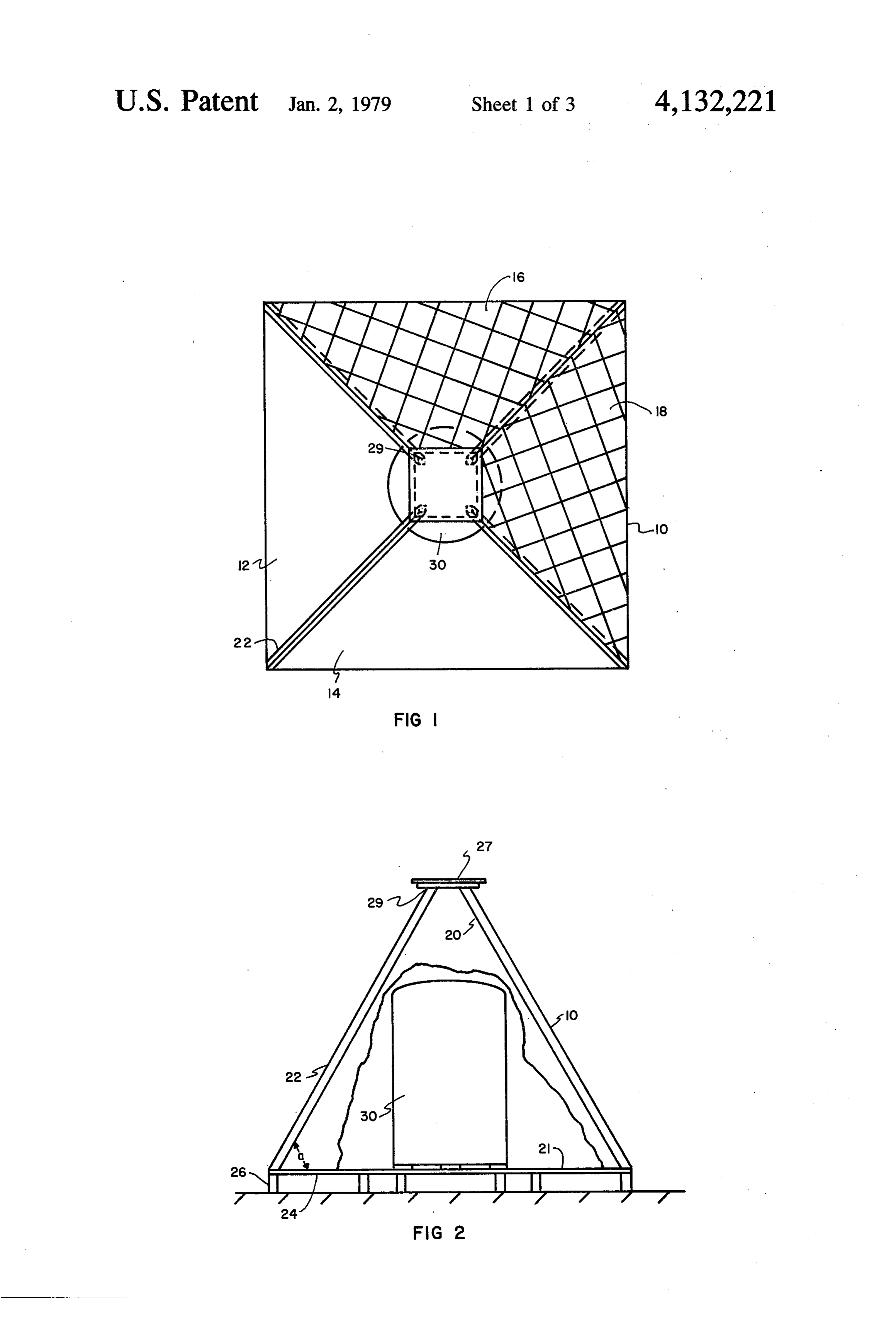
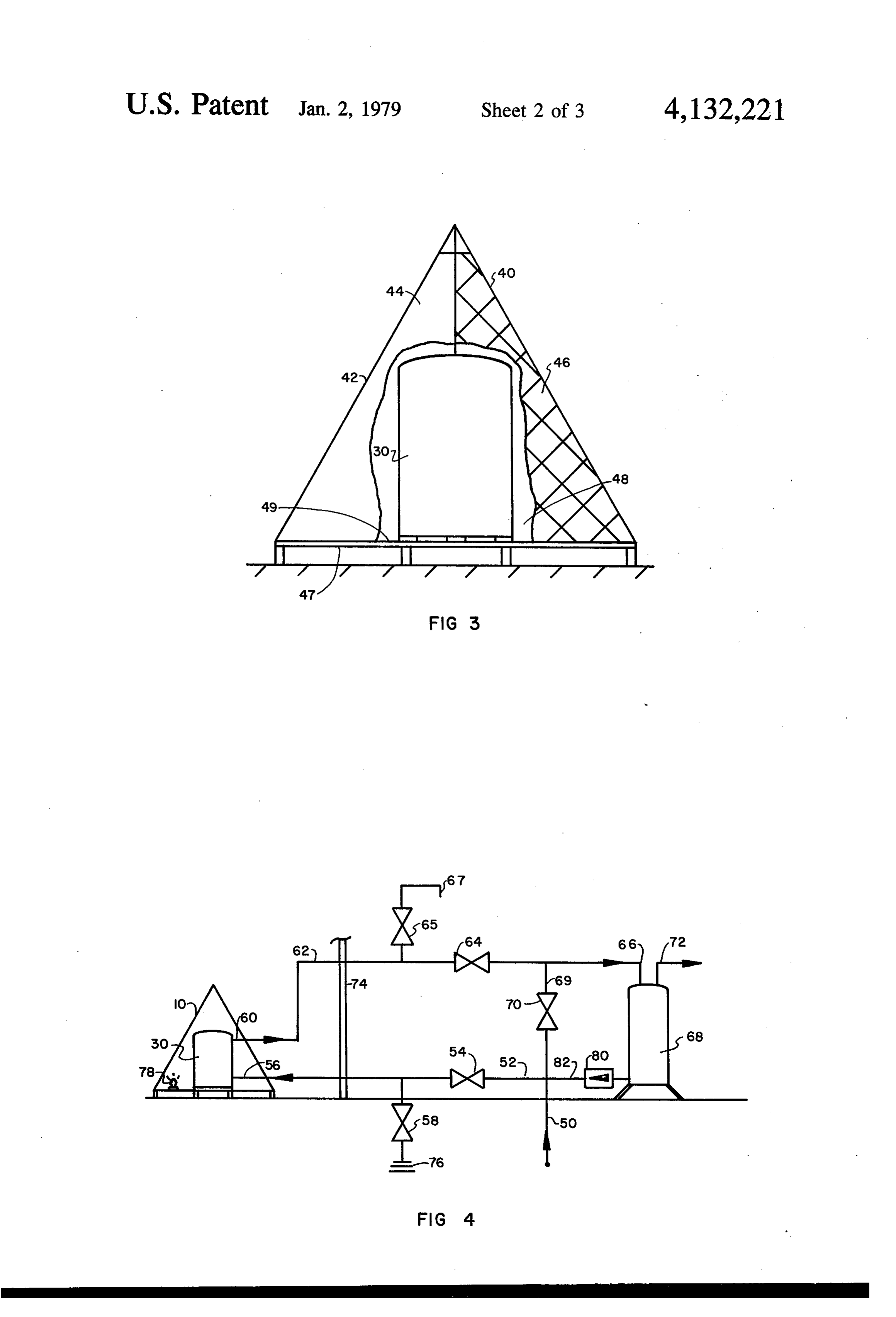
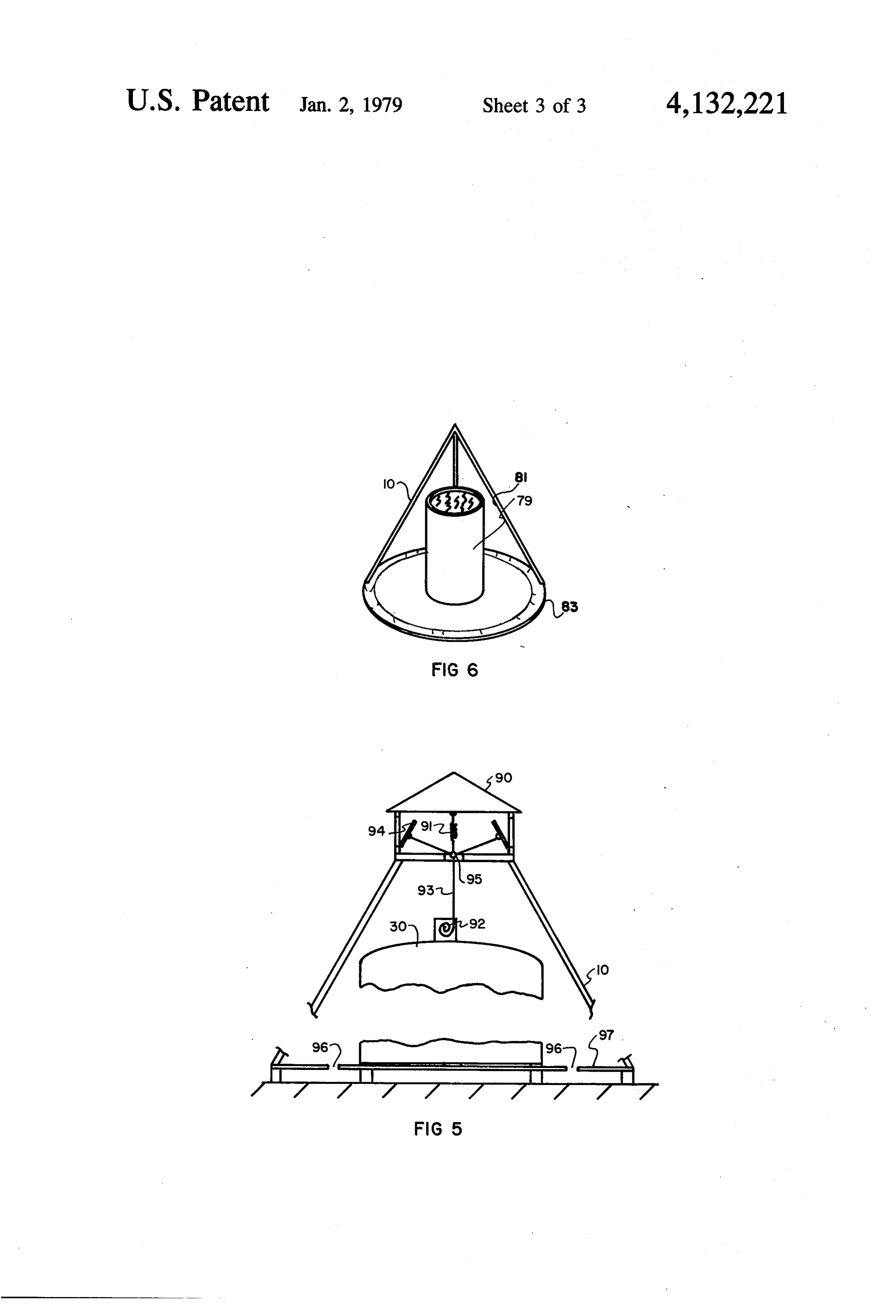
use of a special fluid which flows between the heat FIG. 2 is an elevation view with a portion of the side receiver and the heat exchanger in order to avoid corro wall cut away to illustrate the interior arrangement. sion and deposits on the passageways of the heat re 35 FIG. 3 is an elevation view of an alternate form of ceiver, which would render the receiver inoperative or this invention wherein the enclosure is conical. ineffective after a relatively short period (interms of the FIG. 4 is a schematic illustration of a complete water typical and expected life a heat system or even a hot heating system as contemplated by this invention. water system of 5 to 15 years). FIG. 5 is a diagrammatic illustration of a system for In an effort to solve some of the foregoing problems, automatic introduction of cooling air into an enclosure it has heretofore been proposed that where the object is to prevent overheating.
to heat water, a potable hot water tank itself be encased FIG. 6 is a diagrammatic illustration of an embodi in a heat receiving enclosure, and that in addition to ment of the invention used for distillation. utilizing direct radiation from the sun, some reflected OETALED DESCRIPTION OF THE radiation be captured and furnished to the tank. One 45 DRAWINGS such system is illustrated in the September, 1976 issue of
"Popular Science' magazine, starting on page 101. This Referring initially to FIGS. 1 and 2, a pyramidal system employs an elongated tank in an enclosure with enclosure 10 is constructed wherein triangular panels 12 an elongated front and with two of the sides forming a and 14 are light transmissive, and triangular panels 16 light transmissive trapizoid. The back side, with a re 50 and 18 are opaque and constructed with an interior flective inner surface, is parallel to the front side, and reflective surface 20. Additionally, the surface 21 of the top and bottom sides are perpendicular to the plane base 24 is reflective. The angle "a" (measured vertically of the other sides and are heavily insulated. A difficulty from the horizontal) for the panels would be in the range with this configuration is that for optimum perfor of40 to 80. The panels are supported on frame members mance, it must be adjusted in attitude for the latitude of 55 22 which are supported at their bottom by base 24, the location and as a function of the altitude (varying typically of plywood, this base then being supported by with seasons) of the sun. Preferably, some azimuth pillows or elongated planks 26. The tops 29 of frame changes should be made through the day, i.e., tracking members 22 are connected, by means not shown, to rain of the sun, for best solar energy capture. cap or plate 27 which additionally functions to gener Considering the foregoing, it is an object of this in ally prevent leakage at the point of connection of the vention to overcome the stated problems, and particu panels at the top. As a typical illustration, the base of larly to provide a collector which both directly heats each wall panel would be approximately 64 inches, and potable water, is long-lasting, and is of a configuration the height of the unit would be approximately 50 inches which provides a substantial measure of angular com with rain cap 27, and 56 inches without rain cap 27. In pensation, enabling it to be constructed with a fixed 65 the center of enclosure 10 is positioned a water tank 30, orientation, and yet be of improved effectiveness de typically holding approximately 48 gallons, and having spite significant variations in both azimuth and altitude a diameter of 20 inches and a height of 32 inches. With (seasons and latitude) of the sun. this configuration, the tank extends upward a generally 6 maximum amount within the enclosure, that is, to a exit line 72 connects from hot water heat 68 to points of point where there is small clearance between the top of usage (not shown).
Valves 54, 64, 58, and 70 may be either manually or the tank and closest engagement to side wall panels.
Wall panels of the reflective portion of the enclosure, 5 automatically operated. For example, typically, valves would be thermostatically closed and valve panels 16 and 18, would typically be constructed of wood, metal, fiberglass, or a plastic material, such as 70 thermostatically opened whenever the temperature in tank 30 drops below the temperature of the water styrofoam, with reflective surfaces 20 and 21 being a from reflective coated mylar or of reflective aluminum foil. wouldsource inlet 50. When this occurs, water flow be blocked into tank 30 and would be directly
Light transmission panels 12 and 14 are typically 10 furnished formed of a transparent or translucent plastic material. drops to atovalue hot water heater 68. When temperature at which freezing is likely to occur,
Top plate 27 may simply be of wood or metal construc valve 58 would typically tion and may alternately embody or support a coupla to drain tank 30, air being be thermostatically operated admitted to tank 30 through which would have thermostatically controlled vents to air valve 65. Typically, these valves and hot water tank enable excess heat in the enclosure to be discharged, if 15 68 would be inside a building, as suggested by building such should occur. Alternately, in order to effect safe wall 74, with an appropriate drain line extending out operating conditions, a pressure relief valve may be side the building from valve 58 which would typically connected to tank 30 which would simply open and discharge any unsafe pressure condition arising from drain into a sump in ground 76. If desired, a lightbulb 78 too high a temperature in the enclosure and causing 20 closure 10heating or other element may be employed within en provide heat in the enclosure sufficient to steam to be formed.
Where additional heating capacity is desired, a plural likelihood of freezing). in tank 30 (or reducing the prevent freezing of water ity of solar heaters or collectors of the type shown in Where water heater 68 is located above tank 30, a FIGS. 1-3 would be employed, with water connections circulation of water between the tank and water heater in series, that is, the top or exit connection of one tank 25 may be effected by thermal pumping, it only being would be connected to the entrance or bottom connec necessary to connect a check valve 80 in a line 82 be tion of the tank of the next in the series of solar collec tween the bottom of water heater 68 (as by connection tors. As a further feature of this invention, particularly to the bottom drain of the heater) and line 52. Thus, by where a plurality of collector assemblies are connected convection, solar heated water would rise out of tank in series, there may be added means for the heating and 30 30, flow through line 62, and exit into water heater 68, storage of relatively large quantities of water, enabling with the cooler water in the bottom portion of water storage during periods of reduced or no sunlight. By heater 68 returning to tank 30 via lines 82 and 52 and such an enlarged system, there may be provided means through check valve 80, and thus be circulated. Check for both heating domestic water and means for space valve 80, of course, would prevent a back flow into the heating. For example, in such an arrangement, the tem 35 bottom of the water heater. By this system, losses in hot perature of water in tank 30 would be sensed, and when water heater 68 may be continuously made up and sufficiently elevated, would be pumped between tank 30 stored by heated water from tank30so long as sufficient and a storage tank, for example, the latter having 300 to sunlight were present.
800 gallons. Domestic hot water would then be fur While the system thus far described is indicated for nished to an inlet of a standard hot water heater by the purpose of heating water, it is to be appreciated that running a water inlet through a heat exchanger in the tank 30 may be a cavity through which air is moved and water storage tank to thus effect supplemental heating heated or a heat sink material such as sand or rocks as in the case of the embodiment of the invention shown placed in the container to accept and store heat for use in FIG. 4. Heat for space heating would be obtained by in some other structure coupled by air ducts to tank 30. pumping water from the storage tank through a heat 45 It is to be further appreciated that the embodiment of exchanger connected in the heating circuit with a this invention may be scaled upward or downward, for blower system, typically a hot air circulating system example, a camping or portable model might typically already available in the structure to be heated. have an enclosure with a two-feet square floor surface, FIG. 3 illustrates a conical enclosure 40 wherein the enclosure being 20 inches high, and the tank having one-half of the side walls, the front half 42, as shown, 50 a five-gallon capacity and simply being made in the would be formed of a light transmissive material 44, and form of a plastic bag. As still a further application of the the other half, the back half46 being of opaque material, present invention, it may be employed as a fresh water having an inner reflective surface 48. The inside of base generator. In this application, as illustrated in FIG. 6, 47 would have an inner reflective surface 49. Inside the top of collector tank 79 would be opened to within enclosure 40 would be a water tank 30. 55 enclosure 10 and brackish or salt water pumped or Referring to FIG. 4, fresh water, typically from a poured into the tank (below the level of the opening). In waterline source inlet 50 running to a residence, would either case, it is to be appreciated that any typical open be tapped; and a line 52, having a valve 54 in it, is con ing in the top of the tank, such as by a connecting pipe, nected from this source inlet to tank inlet 56 at the will suffice. Solar heat would cause the water in the bottom of tank 30. Between valve 54 and inlet 56 there tank to be evaporated, and the evaporated water would would be a drain valve 58. An exit 60, typically at the condense on the inside wall 81 of enclosure 10, running top of tank 30, would be connected through line 62 and down the wall to collector channels 83 extending valve 64 to inlet 66 of a standard hot water heater 68. around and attached to the inner side of the walls. There is also connected to line 62 a standard air control As described, the present invention particularly ena valve 65, a valve which will let air in and out of vent 67, 65 bles the implementation of a drain-down type of system but not pass water out. Additionally, there is a line 69 awhich clearly offers advantages over systems which use discrete and separate liquid flow between the collec with a valve 70 directly interconnecting the water source inlet 50 and inlet 66 of hot water heater 68. An tor and storage tank...Thus, drain-down systems allow 7 the use of potable water as the heat transfer liquid and the wall of the enclosure, extending approximately thereby eliminating the need for a discrete heat ex one-half way around the enclosure, and a base of changer. The massive tank-type collector used with the the enclosure having a reflective coating on inner present invention is not detrimentally effected by high sides, and approximately the balance of the wall temperatures which can be experienced with summer 5 surface of the enclosure being light transmissive; solar incidences. Here a substantial balance is achieved and between the energy reflected and collected in the col a tank positioned on and rising from the central re lector tank and that radiated and reflected away from gion of the base of said enclosure; the collector tank. Second, a residual amount of water whereby a significant amount of solar radiation pass (a few gallons) always remains in the bottom of the 10 ing through said light transmissive wall surface collector tank when flow is turned off. This water would directly strike the tank, and a significant would absorb energy through heat evaporazation, and amount of radiation would also initially strike the inner reflective surfaces of the enclosure and be the vapor may be exhausted out through a vent or typi reflected onto the tank, and by this combination, cally a pressure release of the type typically provided 15 any material in the tank quite effectively heated. on hot water tanks. Third, an optional convention con 2. A solar heater as set forth in claim 1 wherein said trol coupla may be installed on the top of the housing of tank has an open top portion.
the system, and by means of a bi-metal temperature 3. A solar heater as set forth in claim 1 further com sensor, doors or slots on the coupla may be opened prising temperature responsive means for opening a when the temperature inside the housing reaches some 20 portion of said enclosure upon the occurrence of a tem selected temperature, e.g., 300 F., which would be well perature above a selected temperature. within the design temperatures of the tank. Such a cou 4. A solar heater as set forth in claim 1 further com pla, coupla 90, is shown in FIG. 5. It employs two prising electrical heating means within said enclosure hinged doors 94 normally biases shut by spring 91. for providing heat within said enclosure.
When the temperature in tank 30 rises above a selected 25 5. A solar heater as set forth in claim 1 wherein the temperature, bi-metallic temperature sensor 92 pulls on sides of the pyramidal enclosure are formed of flat and linkage 93, to which spring 91 and doors 94 are con triangular-shaped surfaces.
nected by ring 95, causing the doors to open. This al 6. A solar heater as set forth in claim 1 wherein said lows cooling air to circulate by natural convention enclosure conical in configuration.
currents from opened slots 96 in base 97 throughout 30 7. A solar heater as set forth in claim 1 wherein a fluid enclosure 10 to thus lower temperature below a selected inlet is connected to a lower region of the interior of level, at which point bi-metallic sensor 92 releases ten said tank, and a fluid exit is connected to an upper inte sion on spring 91, enabling doors 94 to close and stop rior region of said tank.
ping air circulation. 8. A solar heater as set forth in claim 7 further com No pressurization of the system is needed beyond that 35 aprising a first valve, an on-off valve, in circuit between fluid source and said inlet of said tank; and a second supplied by the source, e.g., a municipal water supply. valve, a drain valve, is connected in circuit between said Where used, storage tanks would be insulated and large first-named valve and said fluid inlet of said tank. enough to contain water from the collector tank and 9. A solar heater as set forth in claim 8 further com plumbing lines. Further, where pumping is employed prising:
between a collector tank and a storage tank, the pump an auxiliary fluid heater having an inlet connected to need only a small capacity, sufficient to provide only the exit of said tank and having an outlet connected the needed head for flow. Any residual water left in a to said inlet of said tank; collector tank during winter (and when not used) would a by-pass valve connected in a circuit between said not cause a burst from freezing since there would be 45 source of fluid and said inlet of said auxiliary fluid ample room within the tank for expansion. Thermal heater, whereby fluid may be directly supplied to shock, as when introducing water into the collector said auxiliary fluid heater rather than being sup tank, would not be a problem because of the mass of the plied through said tank;
collector tank, and stresses would be low as it is typi a valve connected between the exit of said tank and cally only lightly pressurized. 50 said inlet of said auxiliary fluid heater; and Having thus described my invention, what is claimed air valve means connected to the exit of said tank for 1S enabling air to enter said tank and thereby to enable 1. A solar heater comprising: the tank to be drained.
a pyramidal enclosure;
Provenance
- Collection
- Patents citing this work
- Pages
- 7
- Method
- pdftotext (the PDF's own text layer) + pdftoppm 300dpi page scans
- Patent office record
- patents.google.com →
- Source
- Google Patents citing-documents table
- Assignee
- Orillion Alfred G
- Published
- 1979-01-02
- Transcribed from
- patentimages.storage.googleapis.com →