

patent · US4249520A
Pyramidal energy collector system
10 February 1981
Text
Page 1bibliographic recordscan →
United States Patent (19)
Orillion
(54 PYRAMDAL ENERGY COLLECTOR
SYSTEM
76 Inventor: Alfred G. Orillion, 1201-E Cleermont
Cir., Huntsville, Ala. 35801
Notice: The portion of the term of this patent subsequent to Jan. 2, 1996, has been disclaimed.
Related U.S. Application Data
(51) Int. Cl................................................ F24, 3
2,167,576 7/1939 Kiser .................................... 126/27 2,213,894 9/1940 Barry .................... ... 126/271 3,244, 186 4/1966 Thomason et al. .. 26/270 3,841,302 10/1974 Fallbel ....................... ... 126/270 4,132,221 1/1979 Orillion .... ... 126/27
FOREIGN PATENT DOCUMENTS
688037 6/1964 Canada ..................................... 26/45 Primary Examiner-Carroll B. Dority, Jr.
Attorney, Agent, or Firm-C. A. Phillips
A radiation energy collector system in which an energy absorber is positioned within a pyramidal enclosure of which approximately one-half of the side area is radia tion energy transmissive, and the other side and base area having a reflective inner surface, whereby radia tion energy passing through the transmissive side area in part directly impinges on the absorber, and in part is reflected onto the absorber.
2 Claims, 16 Drawing Figures
Drawings
Page 2drawing sheetscan →
Page 3drawing sheetscan →
Page 4drawing sheetscan →
Page 5drawing sheetscan →
Page 6drawing sheetscan →
Page 7drawing sheetscan →
Page 8drawing sheetscan →
Page 9drawing sheetscan →
Page 10scan →
it is exposed. A thin transparent covering is usually
PYRAMDAL ENERGY COLLECTOR SYSTEM required to protect the solar cell surface from handling during manufacturing and assembly; beyond this, the
This is a continuation-in-part of application Ser. No. amount of protective covering depends on the planned 800,745, filed May 26, 1977 and now U.S. Pat. No. 5 application. For space applications, sufficient covering 4,132,221. must be used to protect the surface of the solar cells
Background of the invention
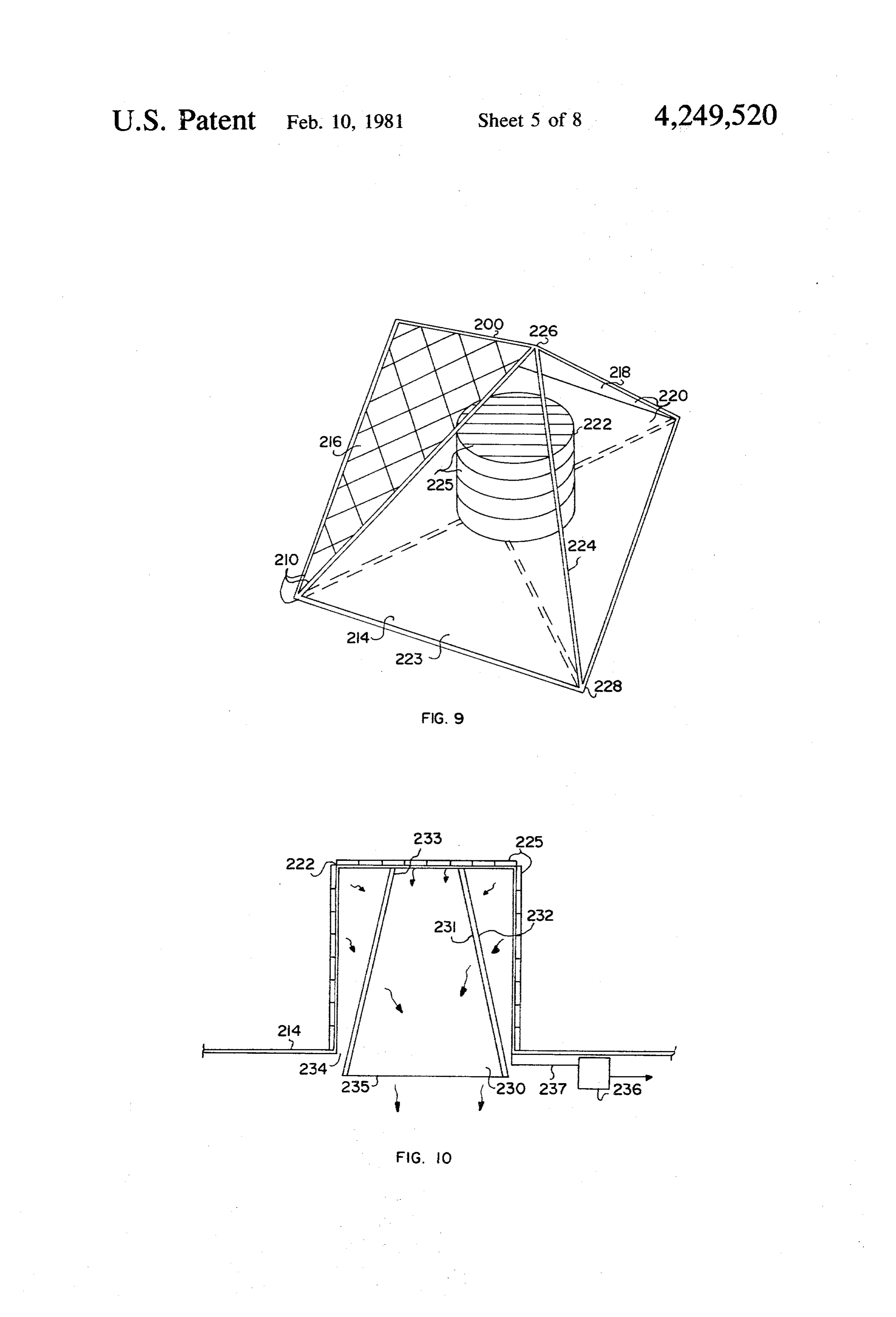
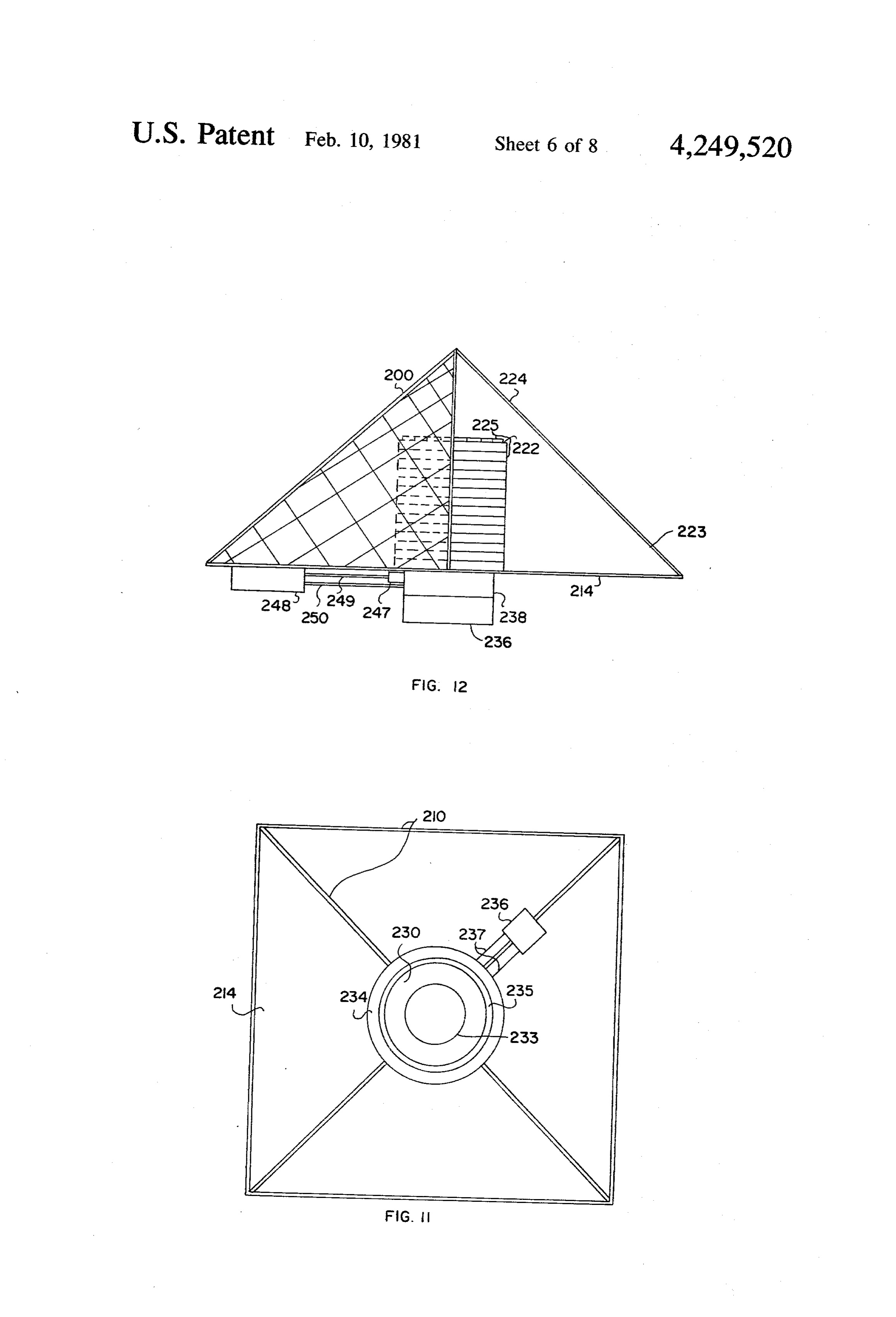
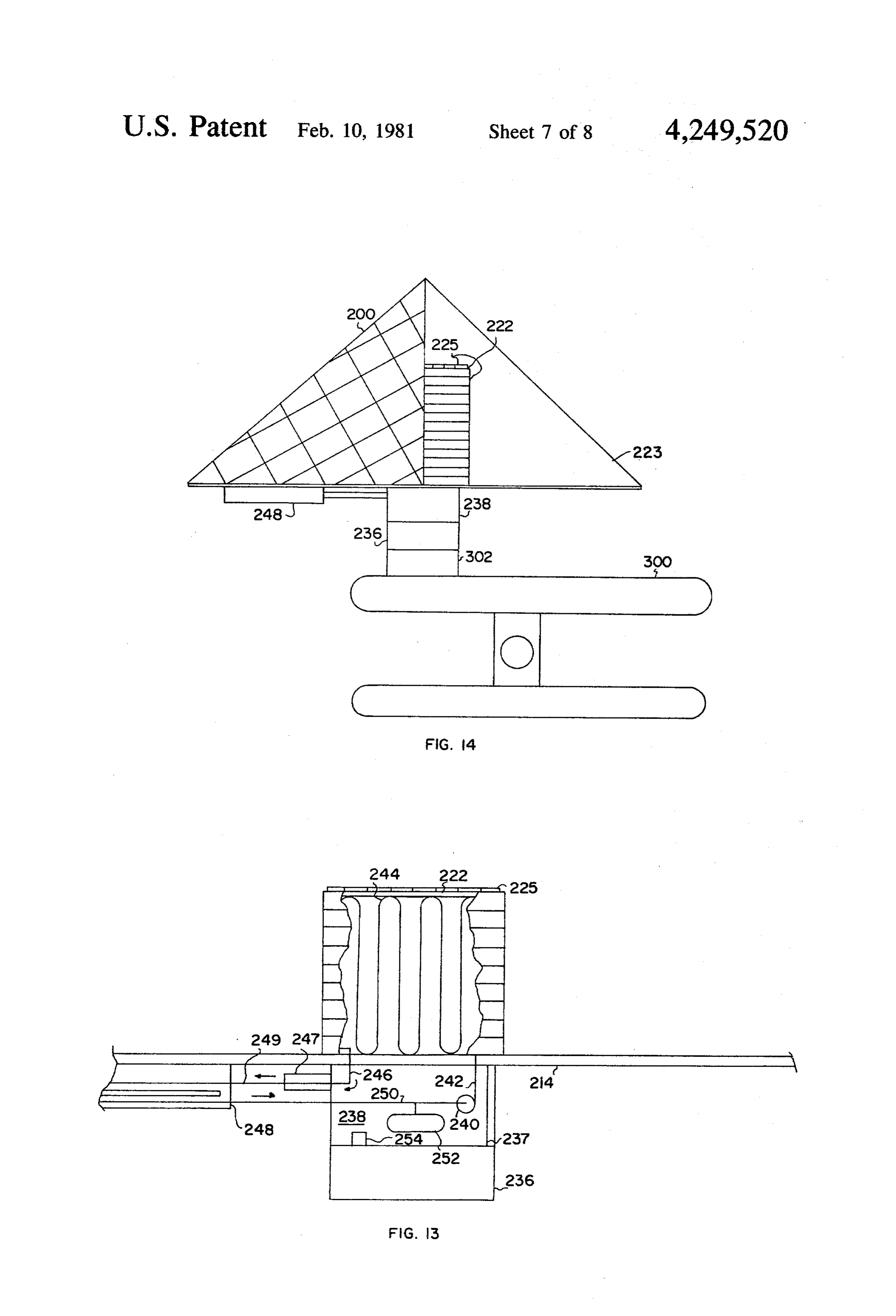
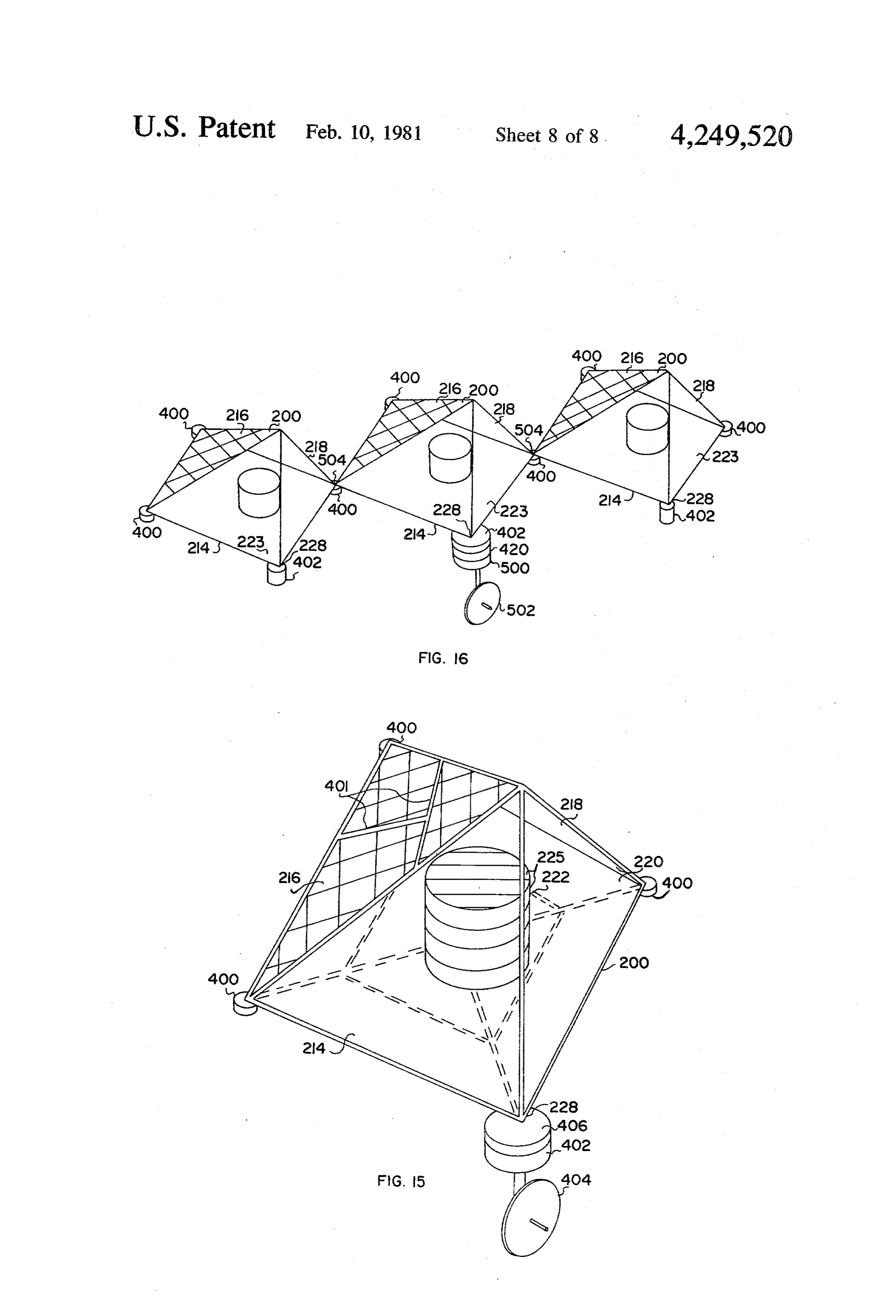
from micrometeorites; generally glass is used as the protective covering to minimize degradation from ul 1. Field of the Invention traviolet radiation. For terrestrial applications, the envi This invention relates to solar energy collecting sys O ronment is more harsh due to dust, rain, hail, and other tems, and particularly to a new combination of an enclo projectiles; glass is likewise preferred, but it is expensive sure and an absorber or collector. and susceptible to breakage from impacts and thermal 2. General Description of the Prior Art stresses. Polymer coverings are less expensive than glass In the past few years, and even before, many configu and are more flexible but degrade in time due to ultravi rations of solar energy collectors have been proposed 15 olet radiation effects. A technique to reduce the cost and some of them marketed. The principal problem and provide some protection to the solar cells is to today with solar energy collectors, either for heat or for utilize a photovoltaic system in conjunction with an electricity conversion, is, as with most products, pro enclosed concentrator device. For terrestrial applica viding an acceptable balance between cost, effective tions, one such device is a linear trough-like arrange ness, and durability. The fact that no single configura 20 ment in which the solar cells are located at the botton tion has really captured the market is an indication that with the sun-sensitive surface facing up toward the top optimum designs are yet to appear. Considering the of the trough, which is covered with a transparent ma known types, perhaps the most common one for heat terial, such as glass. The sides slope up and outward to collection is the flat plate collector wherein a dark col the top and are covered inside with a reflective mate ored heat receiver is encased within an enclosure hav 25 rial. In such an arrangement, the solar cells can be cov ing a transparent or translucent face through which ered with a thin layer of glass as the trough top trans solar radiation directly impinges on the receiver and parent covering protects them from the external envi having a bottom side which is heavily insulated. Typi ronment. A portion of the sunlight entering the trough cally, the receiver contains a passageway or passage would strike the solar cells directly, and most of the ways through which a liquid, to be heated, is circulated. 30 remainder would strike the reflective inner sides and, in Depending upon the material through which the re turn, be reflected and concentrated down onto the solar ceiver is constructed, and thereby often its durability, a cells. Within limits, photoelectric cell power output is flat plate collector costs in the vicinity of $8.00 to proportional to the amount of light striking it. Conse $14.00 per square foot of active surface, with typical quently, concentrators take advantage of this phenome installation costs for a domestic hot water heater system 35 non getting more power out of the solar cells than that running $800.00 to $2,000.00. This high cost is in part obtainabie if the solar cells were in the usual flat plate because of a typical requirement that there be a liquid arrangement. A significant problem with some types of to-liquid heat exchanger to heat potable water and the known photovoltaic concentrators is that they must be use of a special fluid which flows between the heat adjusted in tilt for the sun's seasonal attitude and must receiver and the heat exchanger in order to avoid freez track the sun throughout the day to be effective. ing or corrosion and deposits on the passageways of the In an effort to solve some of the foregoing problems heat receiver, which would render the receiver inopera in collecting solar energy to heat water and to directly tive or ineffective after a relatively short period (in convert to electricity, some design improvements and terms of the typical and expected life of a heating sys research have been made. As an example, heretofore, it tem, or even a hot water system, of 5 to 15 years). For 45 has been proposed that where the object is to heat wa electricity conversion, perhaps the most common one is ter, a potable hot water tank itself be encased in a heat a flat plate module arrangement of a number of photoe receiving enclosure, and that in addition to utilizing lectric or photovoltaic cells, or solar cells (terms used direct radiation from the sun, some reflected radiation interchangeable), encased within an enclosure having a be captured and furnished to the tank. One such system transparent cover through which sunlight passes and 50 is illustrated in the September 1976 issue of "Popular impinged directly onto the solar cells. Typically, each Science' magazine, starting on page 101. This system solar cell is connected to electrical conductors which employs an elongated tank in an enclosure with an elon are brought to terminal connectors from which the gated front and with two of the sides forming a light electrical power may be taken. These flat plate solar cell transmissive trapizoid. The back side, with a reflective modules, or photovoltaic arrays, are constructed such 55 inner surface, is parallel to the front side, and the top that the heat from the photoelectric cells may be re and bottom sides are perpendicular to the plane of the moved from the back side, which are away from the other sides and are heavily insulated. A difficulty with sun, to keep the solar cells within the desired operating this configuration is that for optimum performance, it temperature range. Typically, a number of these mod must be adjusted in attitude for the latitude of the loca ules are electrically connected together, as a photovol 60 tion and as a function of the altitude (varying with sea taic system operational arrangement, to get the desired sons) of the sun. Preferably, some azimuth changes power at a desired voltage level. Currently, the cost of should be made through the day, i.e., tracking of the electricity using such module arrays is from $7.00 to sun, for best solar energy capture. 418.00 per watt. This high cost is due primarily to the To achieve direct conversion of sunlight into electric expensive manufacturing processes to produce the pho 65 ity utilizing photoelectric cells, solar cells, much re tosensitive semi-conductor material for the solar cell. search and development work has been done and is still The delicate photoelectric cell semi-conductor must be being sponsored by the U.S. Department of Energy protected from the effects of the environment to which (DOE). The current mainstream effort by DOE is cen 11 tered around their “Low-Cost Silicon Solar Array' FIG. i0 is a cut-away elevational view of a structure (LSSA) Project. The prime emphasis of the LSSA on which the photoelectric cells are mounted showing a Project is to develop low-cost silicon semi-conductor truncated cone heat sink structure employed to cool photoelectric cells and to assemble the cells into low photoelectric cells in an outer space application. cost modules, each having a power output of approxi FIG. 1 is an underside view of an embodiment of the mately 10 to 15 watts. DOE is also doing some research invention as would be used in outer space and employ and development work on photovoltaic, solar concen ing a truncated cone heat sink. trators. F.G. 12 is an elevational view of an embodiment of Considering the foregoing, it is an object of this in the invention used as a photovoltaic system for outer vention to overcome the stated problems, and particu 10 space use and employing a cooling liquid system to larly to provide an effective solar energy collector remove heat from photoelectric cells. which may be used to directly heat potable water and FIG. 13 is a diagrammatic cut-away view of a liquid /or provide an efficient photovoltaic system that is cooling system for space application of the invention. long-lasting, and is of a configuration which provides a FIG. 14 is an elevational view of an embodiment of substantial measure of angular compensation, enabling 5 this invention as would be used in conjunction with a it to be constructed with a fixed orientation, and yet be space station.
of improved effectiveness despite significant variations FIG. 15 is an oblique illustration of an embodiment of in both azimuth and altitude (seasons and latitude) of the the invention as a large space photovoltaic power gen S. erator being free flying with the ability to transmit
Summary of the invention
power by radio frequencies.
F.G. 16 is a diagrammatic illustration of an embodi
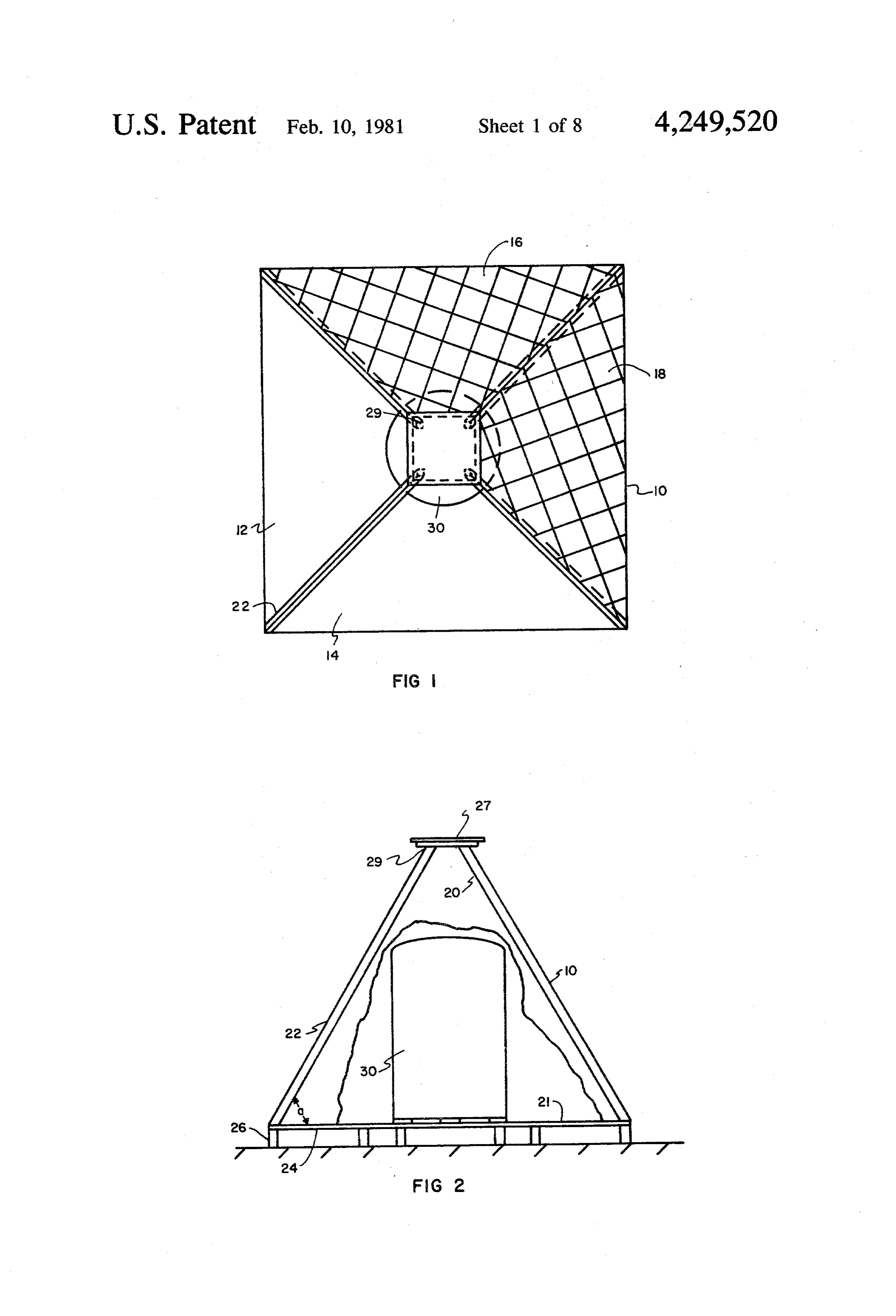
In accordance with this invention, an absorber is ment of the invention as a cluster of photovoltaic gener centrally positioned in a pyramidal structure wherein ators connected together in space for supplying large the floor of the structure is made radiation energy re amounts of power for radio frequency transmission. flective, and the upper region of the structure is divided 25 DETAIED DESCRIPTION OF THE between a side region, extending part way around, DRAWINGS which has a radiation reflective characteristic and a side region which is radiation energy transmissive. Solar Referring initially to FIGS. 1 and 2, a pyramidal radiation would pass through the radiation transmissive enclosure 10 is constructed wherein triangular panels 12 portion of the structure and a portion directly strike the 30 and 4 are light transmissive, and triangular panels 16 absorber and the balance significantly reflected onto the and 18 and opaque and constructed with an interior absorber. This configuration does not require tilting. Its reflective surface 20. Additionally, the surface 21 of design is such that the base is set in a horizontal plane, base 24 is reflective. The angle 'a' (measured vertically and the angle of the sloping sides may be readily ad from the horizontal) for the panels would be in the justed for latitude locations to improve solar collector 35 range of 40 to 80°. The panels are supported on frame efficiency. However, without any adjustment for lati members 22 which are supported at their bottom by tude, and with sides permanently set at a fixed angle in base 24, typically of plywood, this base then being sup the range of 40 to 80, the system is very efficient. ported by pillars or elongated planks 26. The tops 29 of frame members 22 are connected, by means not shown,
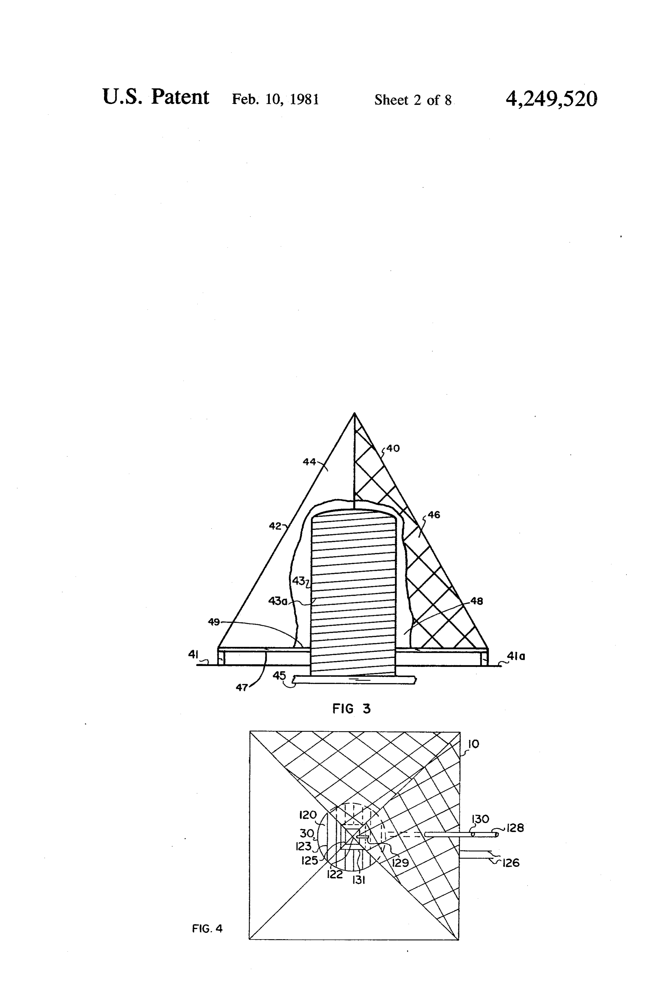
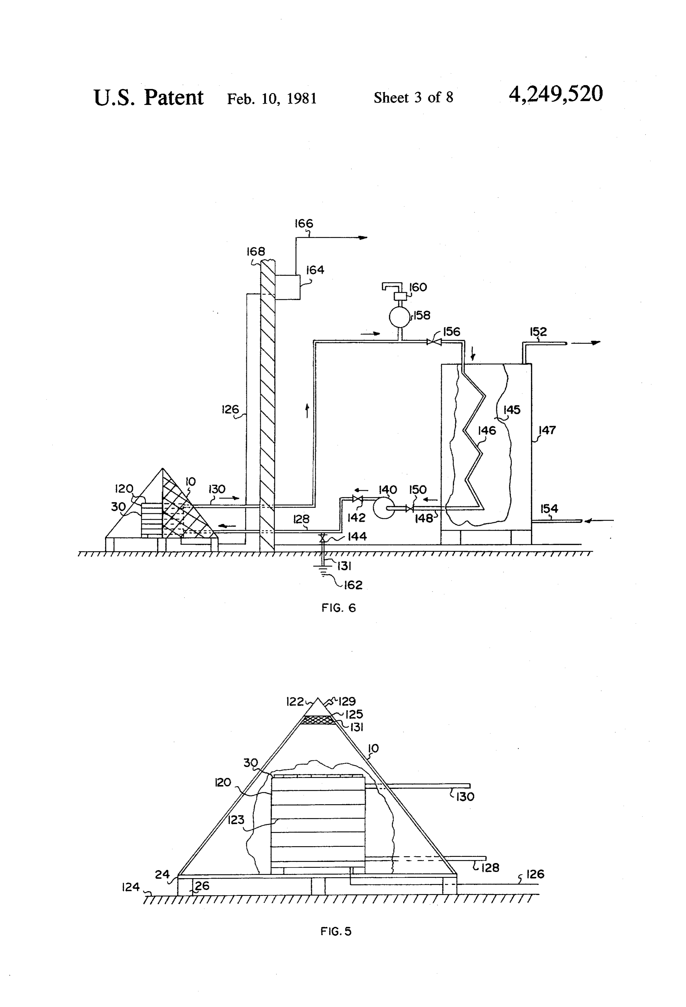
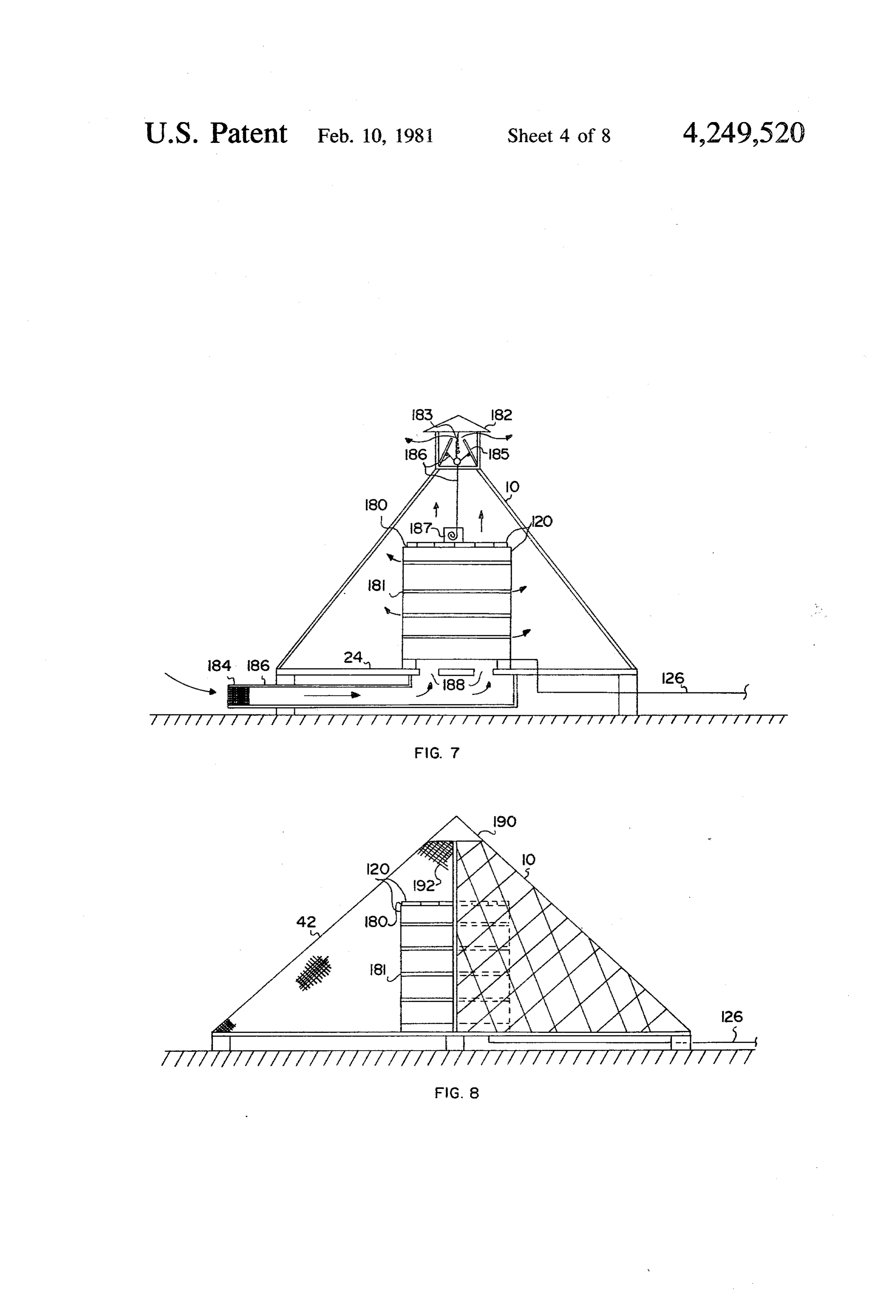
BRIEF DESCRIPTION OF THE DRAWINGS 40 to a flat rain cap or plate 27 which additionally func FIG. 1 is a plan view of an embodiment of this inven tions to generally prevent leakage at the point of con tion. nection of the panels at the top. As a typical illustration, FIG. 2 is an elevational view with a portion of the the base of each wall panel would be approximately 64 side wall cut away to illustrate the interior arrangement. inches, and the height of the unit would be approxi FIG. 3 is an elevational view of an alternate form of 45 mately 50 inches with flat rain cap 27, and 56 inches this invention wherein the upper enclosure is formed of without rain cap 27. Alternately, the whole upper struc one piece and the absorber protrudes through the base. ture may be formed of one piece. In the center of enclo FIG. 4 is a plan view of an embodiment of this inven sure 10 is positioned an energy absorber, such as a water tion in which photoelectric cells are mounted on a tank tank 30, typically holding approximately 48 gallons, and as an energy absorber. 50 having a diameter of 20 inches and a height of 32 inches. FIG. 5 is an elevational view of an embodiment of the With this configuration, the tank extends upward a invention with a portion of the side wall cut away to generally maximum amount within the enclosure, that illustrate an interior arrangement of photoelectric cells is, to a point where there is a small clearance between mounted on a tank. the top of the tank and closest engagement to side wall FIG. 6 is a schematic illustration of a completed sys 55 panels. For purposes of interpretation, the term tank tem in which photoelectric cells are mounted on a tank. implies a single vessel of any shape, e.g., a cylinder or FIG. 7 is an elevational view in which photoelectric sphere, or a cluster of vessels that are interconnected, or cells are mounted on an open grid structure, and a sys a spiral of tubing; all configured to contain a fluid or tem is provided for automatic introduction of cooling allow passage thereof.
air into the enclosure to cool the photoelectric cells. 60 Wall panels of the reflective portion of the enclosure, FIG. 8 is an elevational view of an alternate arrange panels 16 and 38, would typically be constructed of ment in which a transparent side of an enclosure is open wood, metal, fiberglass, or a plastic material, with re to the atmosphere, but covered with a protective wire flective surfaces 20 and 2 being a reflective coated mesh to allow free flow of air over the photoelectric plastic, such as aluminized mylar, or of reflective alumi cells for cooling. 65 num foil. Light transmission panels 12 and 4 are typi FIG. 9 is an oblique illustration of an embodiment of cally formed of a transparent or translucent material, the invention when used as a photovoltaic system for such as plastic or glass. Top rain cap 27 may simply be outer space application. of wood, plastic, or metal construction and may alter 12 nately embody or support a cupola which would have 160 to allow filling of the cooling circuit or to admit air thermostatically controlled vents to enable excess heat to effect draining of the cooling circuit, when drain in the enclosure to be discharged, if such should occur. valve 144 is opened, into sump 162. The liquid in the Alternately, in order to effect safe operating conditions cooling circuit may be pure water, an anti-freeze solu when the absorber is a tank to heat water, a pressure tion, or an oil. Electric power from the solar cells is relief valve may be connected to tank 30 which would collected by power output leads 126 which are con simply open and discharge any unsafe pressure condi nected, typically, to a conventional power output con tion arising from too high a temperature in the enclo trol unit 164; from there the power would be sent to a sure and causing steam to be formed. power storage or distribution system through power FIG. 3 illustrates a modified form of conical or pyra O lines 166. The cooling circuit heat exchanger 146 may midal enclosure 40 wherein the upper structure is be immersed in a liquid, as indicated in FIG. 6, for formed of one piece of light transmissive material. One liquid-to-liquid heat exchange or, alternately, may be in half of the side walls, the front half 42, as shown, would the air and connected to a blower system for liquid-to be of light transmissive material 44, and the other half, air heat exchange. Normally, enclosure 10 would be the back half 46 being opaque as a result of having an 15 external to a building, represented by wall 168, which inner reflective surface 48. The inside of base 47 would houses the valves, pump controls, and other related have an inner reflective surface 49. Enclosure 40 is equipment.
mounted on a roof 41, and tank 43 is formed of spiralled The systems thus far described are for the purposes of tubing 43a which extends into building 41a where it is heating liquids using solar energy, and for the combina supported on a base 45. 20 tion of efficient means of converting sunlight directly Alternately, referring to FIGS. 4 and 5, the energy into electricity using photoelectric cells, and heating absorber within enclosure 10 is a tank 30 having photoe water in the process of keeping the photoelectric cells lectric cells, or solar cells, 120 mounted on outer surface cooled. However, arrangements are contemplated for 123. Typically, this arrangement would be identical to direct electrical conversion within a pyramidal enclo that shown in FIGS. 1 and 2 with tank 30 set upon base 25 sure with solar cell cooling accomplished with air. A 24 above ground level 124 on pillars 26. Alternately, top typical such portion 125 enclosure 10 would be covered by a form photoelectricarrangement cell arrays is shown in FIG. 7 in which 120 are mounted on the periph fitting cap 122 having a vent 129 for venting air in and out through and over water absorbing desiccant bed ery of an open grid structure or shell 180, being hollow in the center, and constructed with air gaps 181 between 131, e.g., silica gel, to minimize water vapor within 30 the arrays, located in central region of pyramidal enclo enclosure 10. Solar cells 120 would be electrically con sure nected to a pair of power output leads 126. It is neces that 10. Installed on top of enclosure 10 in a cupola 182 provides a means to allow air, by convection, to sary to cool the solar cells, and this is accomplished by flow through vent doors 185 as controlled by linkages heat transferring from the back side of the solar cells 186 and bi-metallic temperature sensor 187. At a prede through the wall of tank 30 and hence into a cooling 35 termined liquid, such as water, within the tank. The heated water 185 open,minimum thereby temperature, the cupola vent doors allowing warm air to flow out by would leave the tank through exit line 130 and be re placed by cooler water entering inlet line 128 from a convection forces and be replaced by cooler air enter ing through filler 184, flowing through duct 186, heat exchanger, as, for example, as shown in FIG. 6.
Where a high electrical power output capability is 40 the through vent holes 188 in enclosure base 24 and through inside of enclosure 10. Vent holes 188 are positioned desired, a plurality of solar energy absorbers of the type underneath shown in FIGS. 4 and 5 would be connected together. up shell 180, whereby cooling air would flow In such an arrangement, power output leads 126 of each inside the hollow portion of shell 180 and out be would be electrically connected in a desired series and tween the arrays through air gaps 181 and effectively Mor parallel arrangement to obtain a power output at a 45 cooling the solar cells of arrays 120. Cupola vent doors desired voltage level. In such use, cooling inlet lines 128 185 automatically close at night by return spring 183 in and exit lines 130 of each unit may be connected in a cold climates to reduce the temperature cycling of the parallel arrangement to obtain adequate flow through solar cells. Power would be extracted from photoelec each tank for proper cooling. tric cell arrays 120 through power output leads 126. A typical arrangement for removing heat from within SO Although the temperature controlling action described solar cells 120 on tank 30 is illustrated in FIG. 6. In this herein is an automatic mechanical system, it is appreci case, pump 140 would pump liquid through normally ated that this could be done by electrical sensors and open cut-off valve 142 through inlet line 128 into solar electrical activation of vent doors 185, and, in addition, cell covered tank 30 within enclosure 10. In inlet line an inducted draft or forced draft fan could be em 128 is located a drain valve 144 to effect draining of the 55 ployed.
liquid cooling circuit through line 131 into sump 162. Another air cooling arrangement allowing free flow The heated liquid would leave solar cell covered tank of air could be employed in embodiments of this inven 30 through exit line 130 and pass through normally open tion as shown in FIG. 8. As envisaged, pyramidal enclo cut-off valve 156 and into heat exchanger 146 located in sure 10 would not have a covering on the light transmis large tank 147. The liquid flows through heat exchanger sive side 42, that is, it would be open to the atmosphere. 146 and is cooled by transferring heat to liquid 145, such For mechanical protection of insides of the enclosure, a as water, within large tank 147 and then out of heat wire mesh cover 192 is placed over light transmissive exchanger 146 into line 148, through normally open open side 42. In this arrangement, photoelectric cell cut-off valve 150 and into pump 140. The heated liquid arrays 120, mounted on shell 180, are cooled by the free 145 in large tank 147 is removed through exit line 152 65 flow of air over the solar cells and through air gaps 181. and replaced with cooler liquid through inlet line 154. A connection cap 190, positioned at the top apex of Connected in line 130 is a reservoir/surge tank 158 enclosure 10, connects adjoining ends of adjoining sides which upon the top is located a fill/vent valve system and the wire mesh cover 192.
Page 13scan →
Thus far, emphasis on uses of the invention have been which, in a conventional manner, would convert and terrestrial applications. However, this invention is /or distribute the power for use.. equally applicable for solar energy collection in space, Another arrangement for removing heat from solar particularly for generating electrical power. Of major cells is to utilize a liquid coolant system, as illustrated in concern for space operations is the total amount of mass FIGS. 12 and 13. In this arrangement, photovoltaic that must be sent up from earth to perform this or any arrays 225 on a structure 222 are cooled by coolant coils other function. A feature of this invention is that it 244 attached to the inside wall of structure 222. In gen provides means for higher solar energy collection for a eral, a liquid coolant is circulated by means of a pump given mass in space than systems currently in use or as 240 of coolant control system housing 238 through far as is known, now contemplated. An example of the 10 distributor line 242 to coolant coils 244 and then employment of the present invention in space is illus through exit line 246. As a further feature of this inven trated in FIG. 9. As shown, pyramidal enclosure 200 is tion, and as illustrated in FIG. 3, the coolant fluid as constructed of framework members 210 about the pe heated by the solar cells is fed through power generat riphery of base 214, the two triangular-shaped sides 216 ing system 247 including means (not shown) to convert and 218, and diagonally across the base, for structural 15 the heat energy in the coolant to electrical power. This integrity. Stretched between the framework members generating
Cycle power system may, for example, be a Brayton generator system. Discharge coolant line 210, forming base 214 and the two sides 216 and 218, is a thin plastic covering 200 having an inward facing 249 from the power generating system feeds the coolant reflective surface. Sides 216 and 218 extend approxi 20 through radiant heat exchanger 248 located beneath mately one-halfway around the enclosure; the balance, base 214, which thus performs the function of a heat side 223, is open. A stabilizing strut 224 extends from sink for generating system 247 as well as the solar cell the top apex 226 of the enclosure to opposite corner 228. cooling heat circuit. Line 250 connects the outlet of radiant exchanger 248 to the inlet of pump 240 which of base 214, bisecting the open side 223. In the central recirculates the cooled fluid back to coolant coils 244. A region of enclosure 200 is a cylindrical support struc 25 surge tank 252 is connected ture 222 upon which is mounted photoelectric cell ar necessary fluid expansion in to line 250 to permit any rays 225. With the open side 223 of enclosure 200 ori age. The cooling circuit systemssystem the without dam functions would be ented toward the sun, sunlight would directly strike the electrically controlled by control unit 254, which solar cells of arrays 225 facing the sun and also reflec with pump 240, reservoir/surge tank 252, and along other tive surfaces of covering 220 on base 214 and sides 216 30 elements of the system would be housed in housing and 218. The resulting reflected radiation would be element 238 located beneath base 214. Power from concentrated and directed onto all of the solar cells of photovoltaic arrays 225 would be carried through out arrays 225 covering structure 222. In such an arrange put power leads 237 to power output control unit 236, in ment, the typical dimensions of each the diameter and this arrangement located beneath housing 238, which in height of structure 222 would be in the range of to 35 a conventional manner would convert and/or distribute the length of one side of base 214. By proportionally the power for use. In a space operation, the open side of selecting the height of the enclosure, and hence the enclosure 200, bisected by stabilizing strut 224, would resulting dimensions of sides 216 and 218, concentration be oriented ratios (the ratio of the projected reflective inner sur would alwaystoward the sun, whereby radiator 248 be facing toward black space.
faces to the total area of solar cells) much greater than Applications of the invention for space power gener one can be obtained, allowing high power outputs from ation are many and varied. Typically, a thus powered the solar cells and resulting in fewer solar cells being generator could be connected to a satellite or to a space required for a particular power output level over that station to provide necessary power. As an example, required from a flat plate arrangement. Since the mass shown in FIG. 14 is enclosure 200 with liquid cooled of enclosure 200 is about 10% to 15% of the mass of the 45 photoelectric cell arrays 225 mounted on structure as photoelectric cell arrays 225 and structure 222, this is a sembly 222, and with cooling control system housing mass efficient combination particularly adapted for 238 beneath. A power output control unit 236 is posi space applications. tioned beneath housing element 238, and it is connected FIGS. 10 and 11 illustrate means for removing heat to a space station 300 by adapter 302. With the open side from photoelectric cell arrays 225 in a space applica SO 223 of enclosure 200 oriented toward the sun, radiator tion. Sides 216 and 218 are omitted in FIG. 10 for pur 248 would face toward black space. From power con poses of simplification of illustration. As shown in this trol unit 236, the available power would be routed cut-away view, cylinder support structure 222 includes through adapter 302 to space station 300 for use. an internal heat sink 230 constructed as a truncated cone This invention is also applicable for large space of solid thin material having good thermal conductive. 55 power generating concepts, such as a configuration for properties, such as aluminum. The inner and outer sur a Space Power Satellite (SPS) as being studied by faces 231 and 232 are colored black. The small end 233 NASA. Typically, such an arrangement would be a free of heat sink 230 is connected to the underside of the top flying configuration as illustrated in FIG. 15. In this of structure 222 which supports the photoelectric cells configuration, the dimensions of the base and height of arrays 225. The larger conical end 235 of heat sink 230 60 enclosure 200 would be measured in hundreds or thou extends through an opening 234 in base 214. In this sands of feet, with photovoltaic arrays 225 and structure arrangement, heat from the photoelectric cells would 222, upon which they are mounted, proportionally radiate to a cooler outer surface 232 of heat sink struc sized. The construction would be similar to that de ture 230, be conducted through its thin wall, and then scribed in FIG. 9, except additional support members be re-radiated from the inside surface 231 out to black 65 401 would be required over base 214 and opaque sides space. The electric power from solar cell arrays 225 216 and 218 to properly support the thin plastic cover would be collected and brought out through output ing 220, having an inward facing reflective surface to power leads 237 to power output control unit 236 the large spans. To maintain proper orientation and 14 position, station keeping modules 400 would be located shown in FIG. 8, or photocells 225 shown in FIG. 14, at three of the base corners. These station keeping mod which function to generate electricity, it is to be appre ules would contain control moment gyroscope systems ciated that the structures may be employed to focus (not shown) and liquid rocket reaction control motor energy onto a photocell or photocells of the photoresis systems (not shown) which would respond to signals 5 tive type as where employed in a signalling system. received from orientation control unit 406, located Having thus described my invention, what is claimed under corner 228 of base 214, and by their appropriate S:
actions maintain proper orientation. Under control unit 1. An energy collector comprising: 406 would be located a power station 402. Electric a base and a pyramidal-shaped structure extending power generated in the solar cells would be brought to O around and upward from said base; power station 402, from where a portion would be used a wall region of said structure extending approxi to operate orientation control unit 406 and modules 400 mately one-half way around said base, and said and other systems of the SPS, and the remainder would wall region extending upward linearly at an angle be converted to radio frequency energy to be beamed to of less than 90 with respect to said base; a desired location, such as a receiving station on earth, 5 said base and said wall region having a radiant energy through antenna 404 which can swivel to maintain de reflective inner side, and approximately the re sired orientation. Cooling of the solar cells may be ef. mainder of the way around said structure being fected by either the heat sink concept shown in FIGS. radiant energy transmissive; and 10 and 11 or the liquid cooling system shown in FIGS. an energy absorber comprising a circular spiral of 12 and 13. A number of the configurations shown in 20 tubing rising above the base and positioned cen FIG. 15 may be connected together, as illustrated in trally with respect to said structure, and said ab FIG. 16, for a very large power generating system. In sorber being positioned and configured to: this arrangement, each of the enclosure units 200 would directly receive a portion of the radiation passing be delivered to the desired earth orbit, such as geo through the transmissive remainder of said struc synchrous orbit, there the units would be connected to ture, one another at corners 504 of bases 214 where opaque receive some radiation via a path through said sides 216 and 218 intersect with open sides 223. A sta transmissive remainder onto said reflective side tion keeping module 400 would be located at this junc of said structure and then reflected onto said ture with additional modules located at the other base absorber, 214 corners. A power station 402 would be under the 30 receive some radiation via a path through said open side base corner 228 of each enclosure unit 200 to transmissive remainder of said structure onto collect the power from the photovoltaic arrays of each said base reflective inner side and then reflected unit and to provide power for that unit's operation. A onto said absorber, and central orientation control unit 420, located under to receive some radiation via a path through said power station 402 of a centrally located enclosure unit 35 transmissive remainder of said structure that 200, would provide the necessary orientation control includes both said base reflective inner side and signals to all of station keeping modules 400. By such an said reflective side of said structure; arrangement, each unit can be maintained in proper whereby a substantial amount of all of the radiant position and orientation relative to each other. The energy passing through said transmissive remain remaining power from each unit would be sent by wires 40 der of said structure would be captured by the to a central power station 500 located beneath central absorber, thereby effectively heating fluid directed orientation control unit 420, from where the power through said tubing.
would be converted to radio frequency energy for 2. An energy collector as set forth in claim 1 wherein transmission to earth by antenna 502. said absorber extends through and is supported below While the structures thus far described have utilized 45 said base.
photovoltaic cells for, for example, photocells 120 k k k :
Provenance
- Collection
- Patents citing this work
- Pages
- 14
- Method
- pdftotext (the PDF's own text layer) + pdftoppm 300dpi page scans
- Patent office record
- patents.google.com →
- Source
- Google Patents citing-documents table
- Assignee
- Orillion Alfred G
- Published
- 1981-02-10
- Transcribed from
- patentimages.storage.googleapis.com →