

patent · US4148300A
Solar radiation energy concentrator
10 April 1979
Text
Page 1bibliographic recordscan →
United States Patent (19)
Kaufman, Sr.
(54). SOLAR RADIATION ENERGY
CONCENTRATOR
76 Inventor: Larry L. Kaufman, Sr., 9880 N.
Hawkins Hwy., Brooklyn, Mich.
Int. Cl’................................................. F24J 3/02 52 U.S. Cl. ................................................... : 126/27 Field of Search ......................................... 126/271
l,683,266 9/1928 Shipman ............................... 126/271
1,951,403 3/1934 Goddard .............................. 126/27 1969,839 8/1934 Goddard .............................. 126/271 2,552,237 5/1951 Trombe ................................ 126/271 3,927,659 12/1975 Blake et al. .......................... 126/271 4,029,077 6/1977 Gorniak .... ... 126/271 4,069,812 /1978 O'Neill ................................. 126/270
FOREIGN PATENT DOCUMENTS
547475 8/1956 Italy ......................................... 126/271
Primary Examiner-Carroll B. Dority, Jr.
A solar radiation energy concentrator adapted to con vert solar radiation into useful forms of energy, com prising a base member with a longitudinally extending hollow chamber, said chamber having an open end therein for admission of solar radiation therethrough; integrally affixed in said open end is a convex glass magnifying lens adapted to receive solar radiation im pinging thereon and focus said radiation into a concen trated area on a heat absorbing sensor device located
adjacent in that end of said chamber distal from the open end. The concentrator includes a heat exchanging system integrally juxtaposed with refractory lining on the chamber wall, for delivery of the energy input into the designated system.
3 Claims, 6 Drawing Figures
Drawings
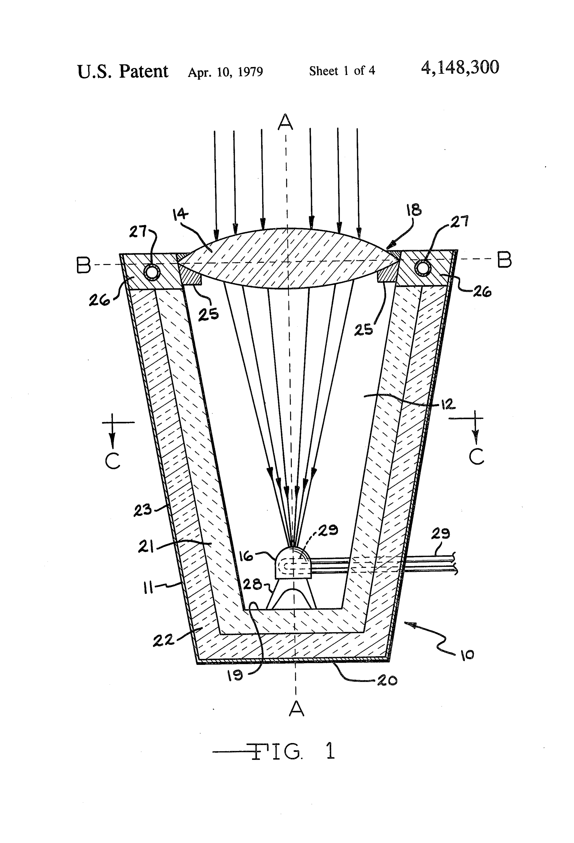
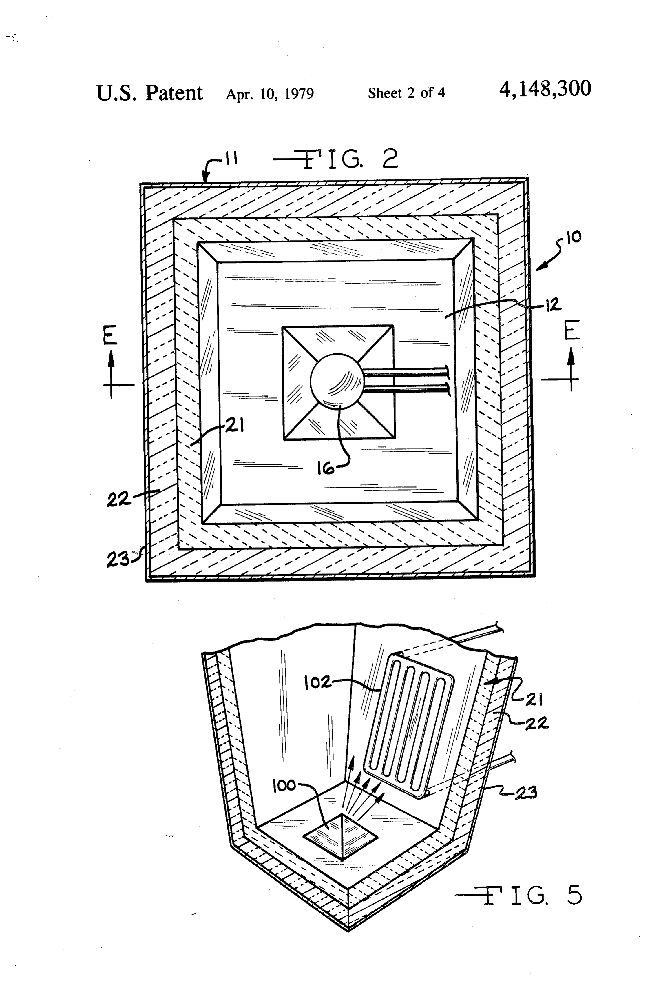
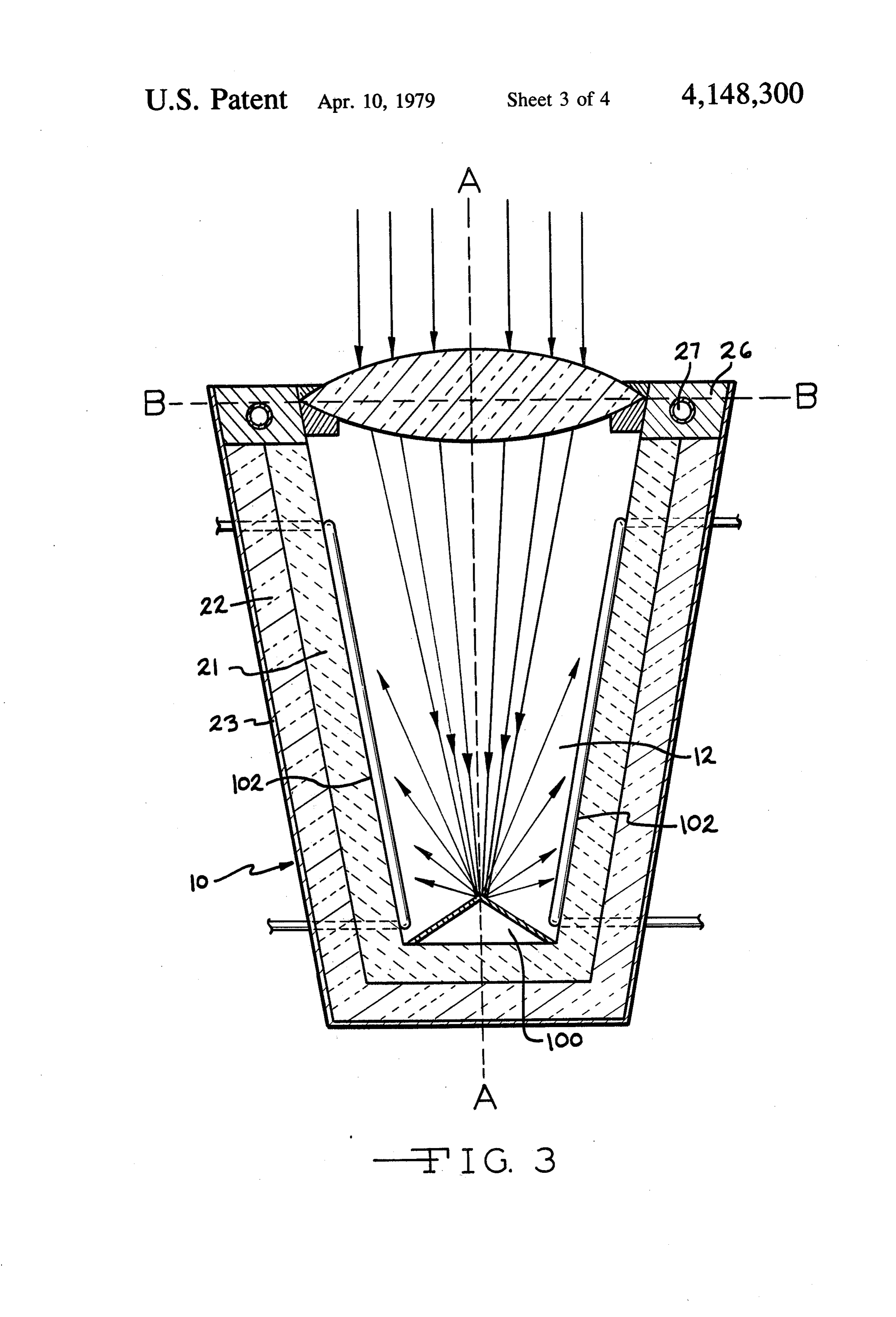
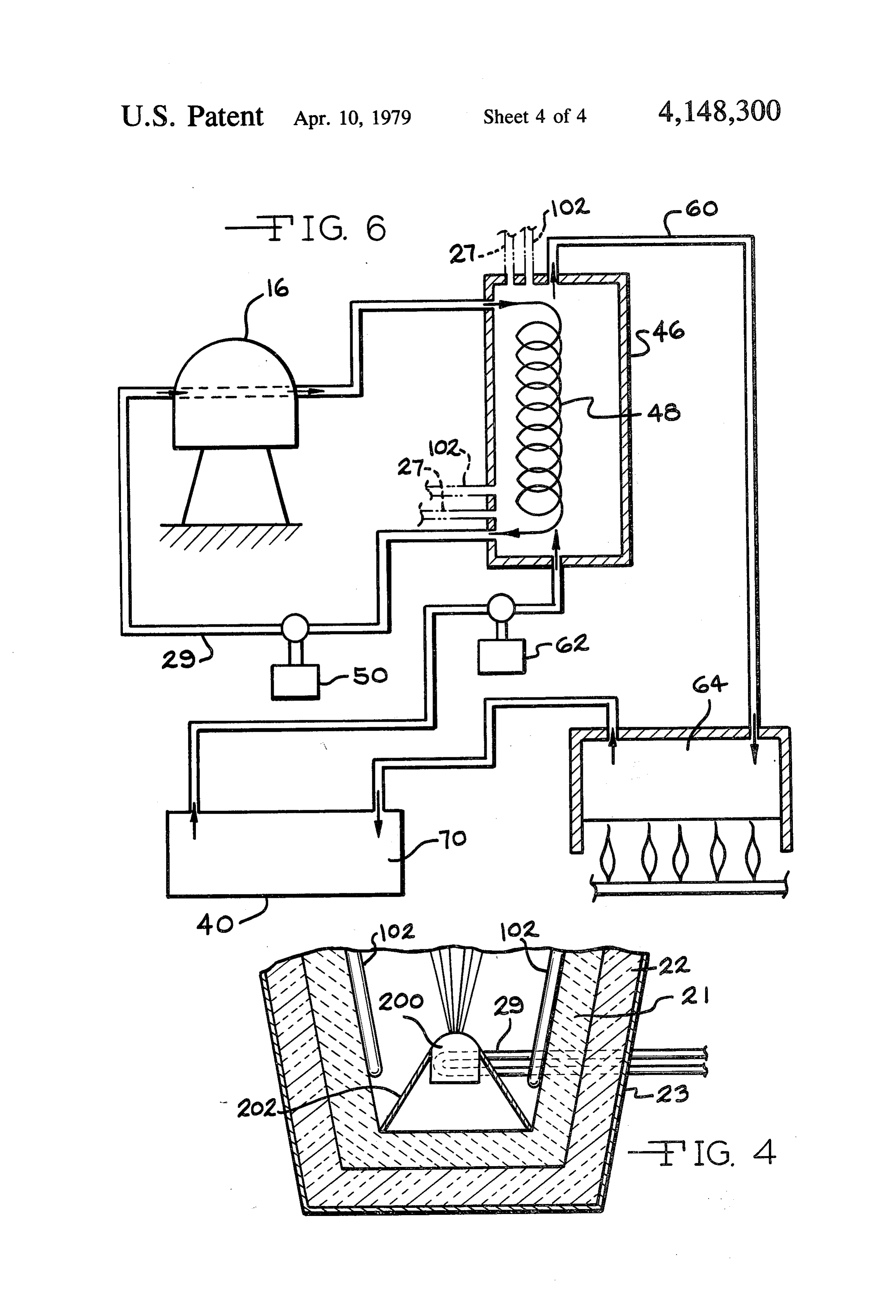
FIG. 6 is a schematic representation of a heat transfer inch thick layer of this refractory material capable of used in conjunction with the subject invention.
Page 2drawing sheetscan →
Page 3drawing sheetscan →
Page 4drawing sheetscan →
Page 5drawing sheetscan →
Page 6scan →
forty days the Earth receives sufficient solar energy to
SOLAR RADIATION ENERGY CONCENTRATOR last a century at present needs; the only problem is that DISCUSSION OF PRIOR ART of effectively harnessing such energy into useful forms. Of course, these values and estimates are theoretical
With the impending energy crisis now facing man, 5 maximums, and as such they are only approached under the necessity and reality of using variant forms of en ideal conditions when the air is clear. Interference from ergy to produce electricity, heat, and other needs is such things as clouds, haze, dust, and smog obviously imperative. Consequently, with the projected reduced reduces the amount of solar energy received, and of availability of fossil fuels, particularly petroleum, there course are important considerations in this harnessing has been renewed emphasis on such diverse energy O process and the efficiency thereof.
forms as wind, the sun and hydroelectric power, among The foregoing data, set forth as background is obvi others. In this regard, solar power devices of various ously indicative of the vast potential of the solar radia types, while certainly not new in basic concept, have tion as an energy source. The enigma and paradox is been conceived in various embodiments to achieve that while this energy source has been omnipresent maximal utilization of the sun's radiation energy. Simi 15 throughout the planet's history, it has not been effec larly, this invention relates to an improved solar energy tively or successfully tapped. As set out in the following converter.
Basic to any comprehension of a solar heater is an discussion, it is apparent that man is still in the embry understanding of solar energy itself. Solar energy is to the use ofhis onic stage of the potential for a more efficient adaptation sun's energy. Indeed solar heaters and electromagnetic radiation which travels 186,000 miles concentrators have been used and moreover many of per second and occupies the spectrum from about 0.25 these have been functional micron to 3.0 microns in wavelength. About nine per moderate degree. However,and successful to a limited or cent of this lies in the extremely short, and invisible, improve existing solar heaters to a progress much is needed to more efficient stage.
ultraviolet region; about forty percent is the visible light Clearly, efficiency then is the ultimate quest in solar factor; and the remaining fifty one percent is infrared, 25 heater development and the determining test for a solar or the long waves. The latter comprises the most signifi heater or collector is how well it performs from a ther cant energy factor in the radiation process. This electro modynamic view. Efficiency is thus measured in terms magnetic energy is the end result of the process of fu of thermodynamics. In short, the inquiry for such per sion of hydrogen into helium, whereby the sun is con tinuously converting its substance into radiant energy. 30 formance is how many B.T.U.'s of usable heat energy Moreover, this process takes place within the sun's for a given period for a given area does it yield, after interior at a temperature estimated at thirty million subtracting uncontrollable factors. From a practical degrees Farenheit, however the surface of the sun has a point of view, a collector's performance is basically a temperature of approximately 10,000 degrees Farenheit function of the temperature at which it operates. The only. However, to appreciate the scope and perspective 35 latter performance is in effect its thermodynamic effi of each such a temperature as ten thousand degrees ciency in converting and preserving the heat it obtains Farenheit, it must be noted that man has only been able on its particular collecting surface. In this regard, the to generate such high temperatures using sophisticated solar energy art has thus far been too much concerned techniques as electrical plasma generation and shock with the collection efficiency and not enough attention tubes. has been given to the energy retention factor. This As a direct result of the sun's fusion an appreciable invention is concerned with both the collection and amount of this radiant energy falls on the earth. In this retention factor. This invention is concerned with both respect, the average amount of the sun energy reaching the collection and retention aspects of the thermody the Earth's atmosphere, amounts to two calories per namic process in solar energy conversion. square centimeter per minute, the mean value of the 45 Relative to the problem of thermodynamic effi solar constant is 1.395 kilowatts per square meter. The ciency, there is an apparent paradox; the higher the total radiation continuously intercepted by the Earth temperature it operates at, the less efficient is the partic (an area of 1.273x101 square meters) is 1.73x10¹⁷ ular collector in many cases. In order to explain this watts. This is approximately 173 trillion kilowatts, or apparent paradox, the question of collector losses must 232 trillion horsepower continuously received. How 50 be ascertained and the rate of such losses, is determined ever, somewhere around thirty percent of the solar by a factor called the "Delta-T" factor. Now, in regard energy reaching the Earth's atmosphere is immediately to long-wave radiation losses, the Delta-T factor is reflected back into space as short-wave radiation. Ap obtained by subtracting the outside ambient tempera proximately forty seven percent is absorbed by the tures, taking wind chill factors into account, and the atmosphere, the land, and the oceans to contribute to 55 temperature inside the collector. Thus, the higher the the temperature of the environment, and this serves as Delta-T factor, the more rapid the loss. Now at a cer the potential useful component for solar energy conver tain point, within a given solar heater or collector, a SO level is achieved where stasis results. This stasis level is For a perspective of total solar energy received, it the point where energy losses moving upward and out must be noted that solar radiation intercepted at the ward from the collector are equal to the input of heat outer atmosphere of Earth has an energy content esti energy. These losses appear to increase at higher tem mated at 5,300 Q per year, where Q= 1 billion2B.T.U.'s peratures, and all major types of solar heaters have this of energy. This is equivalent of more than 200 trillion characteristic to a degree along with other difficulties, short tons of bituminous coal. Every hour the sun show The following discussion of the basic types of solar ers the Earth with about 0.6 Q, and thus in a day the heaters set forth these mentioned thermodynamic ad input is more than 14 Q, and in less than three days the vantages and disadvantages of each type and will serve earth theoretically receives, as much as some estimates as a background for the thermodynamic basis of the of total fossil fuels remaining on Earth. Moreover, in subject invention.
Page 7scan →
Most of the solar energy collectors presently utilized peratures in the 100 to 4000' F. range have not been in homes, and other similar applications, are of the type uncommon at these hot spots. It has been estimated that in order to produce a hot zone of around five inches referred to as flat plate collectors. In this latter type a black plate is covered by a transparent cover plate, diameter a parabolic bowl having a diameter of about spaced a distance of a few inches above the plate, to 100 to 150 feet would be required. The relatively enor allow transfer of the sun's radiation therethrough. The mous size of such a parabolic collector clearly reduces plate material for the absorbing function is usually alu its potential acceptability for most energy applications. minum painted black, and conventionally the sides and By reason of the fact that the sun has an apparent diame bottom of the container for the black surface are insu ter with an angle of approximately 0.009 radians, the lated with suitable materials. The black surface of the ideal paraboloid will concentrate most of the sun's radi plate absorbs most of the sun's shortwave radiation and ation on a spot with a diameter equal to the focal length after being absorbed this energy is reradiated as long times 0.009 radians. The concentration ratio C formed wave radiation. Since glass in the enclosure plate is at the hot spot is found as the ratio of the solar radiation opaque to longwave radiation, the latter is retained in intensity on the hot spot to the unconcentrated direct the enclosure, thereby helping to retain and increase the 15 sun's radiation intensity or intensity at the concentrator total heat in the collector. In this type, the black plate, site, and thus being a heat absorber as mentioned, collects heat and in turn heats a fluid, usually water, flowing immediately = Solar radiation intensity at hots beneath its surface through an appropriate piping sys tem. When the heat transfer medium used is water the 20 system is called a hydronic system, if hot air, then it is Now for a perfectly formed paraboloid, the ratio is a referred to as a hot area system. In a hydronic system, direct function of the paraboloid rim angle 6 and the the resultant hot water generated may be used directly angular diameter of the sun (a=0.009 radians) for heating the building or it may be converted to elec trical or other energy forms. Hot air can be used effi 25 C = a. Sin? 0, ciently as a heating medium without further transforma tion. It is estimated that the efficiency range for such black plate collectors ranges from 40% to 60% for a and Qf=solar radiation intensity at hot spot. Therefore, thirty degree Farenheit temperature rise, and a thirty variation of the paraboloid shape and particularly the percent efficiency rating for a one hundred degree 30 rim angle will determine the degree of concentration at Farenheit temperature increase. Obviously, such effi the focal spot. The more finely drawn into a small size, ciency ranges are not satisfactory in view of the fact the more heat will be concentrated, and thus the higher that in certain areas sunlight does not cover the area the temperature will be generated. The same principles much of the year. While specific devices have been used would apply in a concentrated hot spot using a convex to improve these solar heaters they are still highly ineffi 35 lens as a concentrating vehicle. In each case however, cient, in part from a heat retention perspective, and the whether by paraboloid or by convex lens, the advantage art requires a more efficient and effective methodology of higher temperature realized is accomplished at the of collecting, retaining, and utilizing solar radiation in sacrifice of spreading the accumulated heat over a wide order to economically and successfully rely on solar area. Another disadvantage with existing concentrators heat. is that generally they are structured in such a way that As opposed to the flat plate collectors, solar concen the heat collected is not efficiently retained because of trators are used to harness solar radiation in a more ambient air flows on ineffective structural locks to pre concentrated form and such devices are especially use vent heat losses.
ful to produce temperatures in excess of three hundred As can be readily determined from the foregoing degrees Farenheit for relatively efficient electrical discussion of the prior art, it is not difficult to see the power generation and other applications in which high shortcomings of existing known solar energy devices temperature heat is needed. For instance, such devices from a practical economic standpoint. On the one hand, have been utilized to increase the power output of the flat plate collector is capable of absorbing radiant photovoltare cells in view of the heat generated. The 50 energy over a more widely dispersed area, at low tem most commonly used method of concentrating and perature gradients, while on the other hand, solar con focusing the sun's radiation is by way of reflector sys centrators yield at the expense of wide area dispersal, tem, and for relatively high radiation concentration, the only moderate ideal structure for this purpose is a parabolic bowl. In creases over justtoa limited moderately high temperature in such instances, the central longitudinal axis of the para 55 significant problem of heatarea. Moreover, a real and collection and retention bolic reflector must be directed at all times towards the characterizes the array of known solar heaters. While sun. Further, in solar energy concentrators a heat ex some may be efficient collectors, the retention problem changer is usually located at the focus of the collector, is not solved, and vice versa. As a direct result of this the focus being the focal point of the parabolic shape. latter observation, the need for more effective solar Parabolic concentrators, because of the state of the art, are not used that frequently for most solar energy appli energy efficient solar heaters is most obvious, and the cations, particularly in those situations where the cost efficientinvention subject solar is thus directed to that end of a more heater.
of collecting solar energy must remain low. Parabolic troughs are used as concentrators, although they do not OBJECTS have the same efficiency as parabolic bowl.
Another important facet of solar concentrators is that 65 In view ofofthe foregoing discussion of the prior art they produce hot zones in extremely limited areas, for theItobjects the invention are: is an object of the subject invention to provide an instance the focus in most of the relatively larger solar furnaces ranges from one to two inches, although tem improved solar heating device;
Page 8scan →
A further object of this invention is to provide an the lens is substantially the same size as the inner cir efficient solar energy concentrator; cumferential area of the open end of the chamber. The It is yet another object of the subject invention to chamber itself is in the form of an inverse truncated provide an improved method of utilizing and harnessing quadrahedron, wherein the inner diameter of the lower the maximum effect of solar radiation; extremity is less than the diameter of the upper extrem It is an object of the subject invention to provide a ity. This latter configuration and the precise size and highly efficient solar heater; shape of the chamber is not of critical consequence, An object of the subject invention is to minimize heat however, but as expressed in the following description losses in a solar collector; serves as the most optimal shape. Located within the Another object of the subject invention is to provide 10 lower reaches of the chamber is a heat absorbing body an effective high temperature solar energy concentra connected to an appropriate heat exchanger system, tor; located therein. The framework shield in which the It is also an object of the subject invention to provide chamber is located is comprised of an inner lining made an improved method of retaining the heat in a solar of high quality refractory material, while the intermedi collector; 15 ate lining is made of a low temperature insulating mate Yet another object of the subject invention is to pro rial. A metal cover encompasses the outer shield and vide a method of magnifying the effect of solar energy jacket.
into a higher temperature zone for maximization of the sun's radiant energy effect; DESCRIPTION OF PREFERRED Still another object of the subject invention is to pro EMBODIMENTS vide an improved device for maximizing the degree of Referring now to the drawings in which a preferred concentration of the sun's energy; embodiment is shown, and initially to FIGS. 1 and 2, a It is an object of this application and the subject in solar energy unit 10 is shown as being comprised of a vention to set forth a novel and unique solar energy basic longitudinally extending holding frame member methodology; 25 11 having a hollow chamber member 12 therein, a con An object of this invention is also to provide a solar vex magnifying lens 14 and a heat absorbing body 16 in energy converter which serves to multiply the radiant the form of a black body for the preferable embodiment. energy effect of the sun, concentrating same onto a heat The magnifying lens 14 is situated at the open end 18 of collector for high temperature heat transfer application; chamber 12. Generally frame member 11 is in a verti A still further object of the subject invention is to 30 cally upright position, so for subsequent reference pur provide a solar furnace which maximizes the collection poses such end 18 will be referred to as being in the of heat energy; upper end of chamber 12, while the opposite end 19 Another object of the subject invention is to provide thereof will be referred to as the lower end. The use of a solar heating device which maximizes the heat reten the latter reference system is not to be construed as tion function; 35 limiting the orientation of frame 11 to an upright posi Other and further objects will become apparent from tion such that the longitudinal central axis, defined as the following drawings take in conjunction with the A-A in FIG. 1 is at all times in the vertical upright description of the preferred embodiment. position. In this regard, it is intended that the hollow DRAWINGS chamber 12 in holding frame 11 will be directed towards the sun at desired intervals in order that axis
FIG. 1 is a elevational view from the side, in section A-A is aligned towards the sun, with such axis to be of a preferred embodiment of the subject invention; parallel with the rays of the sun. FIG. 2 is a plan view from the top in section through The under-bottom 20 of the bowl shaped holding line C-C in F.G. 1. frame 11 as represented in FIG. 1 may rest on a flat FIG. 3 is a side elevational view of another embodi 45 floor or the ground, however, any device for holding it ment of the subject invention, in section through line in the desired position of orientation may be used. E-E of FIG. 2; The holding frame 11 is preferably a truncated quad FIG. 4 is a fragmented view in section of an alternate rahedron situated in an inverse position so that its embodiment of the subject invention; smaller end is on the bottom. Frame 11 has a hollow FIG. 5 is a perspective, in section, and partially frag area in its central core, which forms the chamber 12. Immediately adjacent to chamber 12 is a refractory mented view showing the chamber in the embodiment in FIG. 3; layer 21 structured on all four sides, as well as on the chamber bottom 19. There is preferably a four to five
FIG. 6 is a schematic representation of a heat transfer inch thick layer of this refractory material capable of used in conjunction with the subject invention.
55 functioning in temperature ranges of five to six thou
DESCRIPTION OF GENERAL EMBODIMENT sand degrees Farenheit. Immediately outside and adja The subject invention is a solar heating and retention cent the refractory layer 21 is a lining of insulating device used to magnify and thereby concentrate, and material 22, preferably of the low temperature variety. subsequently retain, to a maximal degree the energy of This lining 22 of insulation has the same conforming solar radiation into a relatively small area on a heat 60 configuration as does refractory layer 21, but with lin absorber whereon heat gradients are developed so as to ing 21 situated inside lining 22. An outer wall 23 of yield temperatures up to five thousand degrees Faren suitable metallic substance serves as the covering shield heit or more. The invention is comprised of a longitudi for support frame 11.
nally extending upright hollow reception chamber, It is preferable, although not of critical consequence, with an open end which is exposed to the sun for admis 65 that the longitudinally extending chamber 12 be config sion of the sun's rays. Affixed in this opening is a con ured in the form of a truncated quadrahedron with the forming glass lens having a diameter which is suffi smaller end disposed on the lower side, as seen in FIG. ciently large in order that the outer circumference of 1, and by such configuration the open end 18 of cham 9 ber 12 will have a greater girth than the bottom 19 of the preferable embodiment.only however, this dimension is a recommended size for the said chamber. While the preferred designated em larger or smaller depending The exact diameter may be bodiment for chamber 12 is that of a truncated quad utility needs of the solar heater inexact on the structural and rahedron, as discussed, the use of a convex magnifying 5 more, the thickness of the lens willquestion. vary Further depending lens 14 imposes no requirement that the chamber 12 be of any particular shape or configuration for purposes of upon the exact needs involved. ... " embodying the concepts of this invention. Conse solar The function of the lens 14 is to converge the rays of quently, a chamber having a parallelopiped form or a lens and radiation impinging upon the upper surface of the curved form, such as the well known parabolic cham to focus the converged rays downwardly into ber, could also be used, as desired by those who imple- 10 aabsorbing small zone on the upper spherical surface of the heat body 16. The converged solar rays as focused ment this invention.
The magnifying lens 14, as stated above, is preferably on this spherical surface of heat absorbing body pro of a double convex configuration as represented in the duce temperatures in the range of four to six thousand sectional view of FIG. 1. Referring to FIG. 1, the lens 15 degrees Farenheit. . 14 is inserted and affixed into the open end 18 of cham beAs an alternative to the convex glass lens, use could made of a fresnel type lens, which is a thin flat sheet ber 12 so that its lateral axis B-B lies substantially of transparent plastic on which is mounted a plurality of perpendicular to the longitudinal central axis A-A of
Chamber 12. The outer lateral perimeter of lens 14 is very fine ridges which are molded in concentric circles shaped for compatible and permanent juxtapositioning from the center of the rim. Each such rim is appropri into the upper open end 18 of chamber 12 in order that 20 ately beveled in order to refract light in the same func the lens covers the entire opening 18. For purposes of tional capacity as a conventional convex magnifying lens. Also, a thin plate of glass can be used in this capac affixing lens 14 into opening 18, a peripheral ledge 25, as ity in low temperature applications. seen in FIG. 1, encircles the inner wall of chamber 12 adjacent with upper end 18. The top surface of this 25 ofThe the foregoing description relates to one embodiment invention, and there may be other embodiments ledge 25 is curved and the bottom surface of the lens 14 which the invention can assume. For instance, in the is affixed to the top surface of the ledge by appropriate alternative embodiment epoxy or other bonding methods. However, any reflector member 100 isshown in FIG. 3, a multifaceted used at the bottom of chamber method of affixing the lens 14 to the ledge 25 may be 12, as represented, in lieu of a heat absorbing body 16. used, depending on the weight and material factors 30 In this latter embodiment, a four sided quadrahedron or involved. pyramid-shaped member with each side being made of Located at the top of the supporting frame 11 is a cooling head 26 of toroidal or corresponding shape, reflecting material forms reflector 100. Also, in this which extends around the upper perimeter of frame 11, embodiment, conjoined to each surface, of refractory lining 21 is a heat exchanger 102 comprised of an open as depicted in FIG. 1. This cooling head 26 serves to 35 lattice like matrix of black coated piping, as shown in dissipate heat drawn to the top of frame 11 through more detail in FIG. 5. In all other respects the embodi refractory layer 21 and for this purpose a heat exchang ing system is provided in the form of water or air tubing ment in FIG. 3 has a supporting frame 11, chamber 12, refractory walls 21, insulating wall 22, cooling head 26, 27 integrated directly through the cooling head, as and lens 14, which are constructed the same as those in represented in FIGS. 1 and 3. Thus any heat collected the embodiment shown in FIG. 1. or drawn through the cooling head can be used as an By using the embodiment shown in FIG. 3, heat fo additional input factor into the system to be energized. cused onto reflector member 100 is reflected to refrac The heat absorbing body 16 in the embodiment tory wall 21. This reflected heat will either impinge shown in FIG. 1 located at the lower end of chamber 12 is affixed to the floor 19 of chamber 12 on a metallic directly upon heat exchanger 102 or upon the refractory stand 28, as represented in FIG. 1. The heat absorbing 45 wallFIG. 21. In the second alternative embodiment, shown body shown is preferably hemispherical in shape, with in 3, the heat that impinges by reflections upon the spherical surface being directed upwardly as the heat exchanger 102 will cause whatever air or liquid receiving surface for the solar radiation. This receiving therein to be heated. This newly heated air or liquid will then be directed to the connected specific energy input surface is made of a black material of highly absorptiv 50 system ity in order to maximize its heat absorbing function. The tion, thedesired,heat as represented in FIG. 6. Now, in addi that does not impinge upon heat ex shape of heat absorbing body is not critical, however, it is found that a rounded, spherical shape may be the changer 102 will be directed onto the refractory wall 21 most optimal for the embodiment represented in FIG.1. and will cause the refractory material therein to in A heat exchange and withdrawal system in the form of 55 crease in temperature. This heat generated in the refrac piping 29 is located partially within heat absorbing body tory wall 21 will rise by conduction upwardly in the 16. Specifically, in the embodiment shown in FIG. 1, refractory wall, along each side of chamber 12, up to piping 29 extends to and from the designated input head 26. Therefractory the top of the wall where it meets the cooling system, which is analyzed hereinafter, to the heat ab upwardly, andheat in refractory wall will tend to rise sorber 16. Air, water or a similar liquid, depending on -be enhanced bythis upward conduction movement will the fact that the refractory walls are the compatibility of the input system, is drawn through lined on their outer and bottom peripheries by insula piping 29 to absorb collected heat from heat absorbing body 16. This heated air or liquid passes into the specific tion layer 22, as shown in FIGS. 1 and 3. This insulation layer 22, will help block any conductive heat movement input system application, as represented in FIG. 6.
Magnifying lens 14 is preferably a double convex lens 65 in the direction of layer 22, thus in effect helping the upward conductive movement of heat in layer 21 to made of glass, and the exact curvature of this lens will cooling head 26. The cooling head 26 will thence, and vary depending on the degree of focus desired onto the continuously thereafter, absorb the heat from refractory absorbing body 16. Lens 14 will preferably be approxi wall 21 and pass such transferred heat to the heat trans mately three feet in diameter for home utility purposes, 10 fer piping 27 in the cooling head. Thus, both heat ex 50 serves to pump the water or air through the piping changer piping 102 and 27 will pass heat into the heat 26, so as to cause it to circulate through the absorbing system, as schematically shown in FIG. 6. As indicated body 26. The heat exchanger 48 in tank 46 serves to by this dual heat collection system there is virtually no transfer the heat from the water in piping 26 to hot air, heat loss of collected heat, rendering the solar heater as an example of the possible end use of the solar radia highly efficient. tion captured. Furthermore, heat from the fluids com Yet another embodiment of the subject invention is ing from heat exchangers 27 and 102, for the embodi seen in FIG. 4, in which a hemispherical heat absorber ments shown in FIGS. 3 and 4 can be drawn into the 200 is combined with a reflector member 202 having the systems shown in FIG. 6 to augment its total effect. form of a truncated quadrahedron, Glass or aluminum O As can be ascertained from the foregoing description, can be used as the reflector material, since glass has a the operation the subject invention serves not only to reflectivity quotient of from 0.53 to 0.89, while alumi maximize the capture of the sun's radiant energy but num has a quotient range of from 0.72 to 0.96. In all also maximizes the retention process relative to such other respects, the chamber 12, the lens 14, the cooling heat collected. By the combination of the reflector sys heat 26, and other features of this embodiment are the 15 tems with the heat absorbers, the refractory wall, and same as those features of the embodiment shown in the sundry heat exchangers, the efficiency of the device FIG. 1. In the case of the embodiment shown in FIG. 4, is maximized. It must be remembered, as indicated here the absorbing body 200 is equipped with piping 29 in inabove for the ideal paraboloid of one hundred percent corporated therein, and this latter heat exchanger pip efficiency operating in space, the temperature of a black ing possesses the same attributes as the heat exchanger 20 body therein would reach approximately ten thousand piping 29 as shown in FIG. 1. Additionally, in the em degrees Farenheit maximum. However, since most sur bodiment shown in FIG. 4, the heat exchanger 102 faces are not perfect reflectors, and since the atmo located adjacent the refractory wall 21 is identical in sphere reduces incident radiation of the sun, the resul shape and function to the heat exchanger described as tant highest reported temperatures of parabolic reflec used in the embodiment shown in FIG. 3. Reflector 25 tors is in the vicinity of 4000-6000 F. But, the problem member 202 serves to reflect radiation from lens 14 onto with such reflectors has been that while hot tempera the heat exchanger 202 and refractory wall 21, as de tures have been generated, total heat accumulated and scribed before. Thus in operation, the embodiment retention problem is not solved.
shown in FIG. 4, has a threefold heat collector and This invention resolves the heat retention problem retention system and corresponding apparatus. Specifi 30 considerably by the multifold heat absorption and trans cally, when heat impinges upon the exposed black hemi fer mechanisms employed, as described. spherical surface of heat absorbing body 200, such heat In a solar concentrator of the convex lens type herein will pass through its heat exchanging system to pipes 29. described or the parabolic bowl type, it may be desir This heat in the form of hot water will travel directly to able, but not always necessary, for a continuous track the second heat exchanger shown in FIG. 6. If air is 35 ing of the solar device directly into the sun's rays. In used in pipes 29, a second heat exchanger may be ren other words, it may be feasible to have the solar concen dered unnecessary. Any minimal heat reflected off heat trator maneuvered periodically to receive the sun's rays absorbing body 200 and additionally any radiation re directly onto the collector. Relative to the embodiments flected off reflector member 202 will be directed onto shown in FIGS. 1, 3, and 4, this requirement means that heat exchanger 102, identical to the one shown in the the axis A-A be aligned directly parallel to the existant embodiment represented in FIG. 3, and which heat axial direction of the sun's rays at a given time interval. exchanger will be heated proportionately and pass its Indeed, the tracking function may be complex process heat through its pipes as a second heat receipt source by which appropriate mechanical or electronic equip into the heat input system shown in FIG. 6. Now, as a ment is needed to track the collector into the sun's rays. third collection and retention source and mechanism, 45 It is beyond the scope herein to discuss in any detail a heat absorbed through the cooling head 26, from refrac specific tracking system, however it is sufficient to state tory wall 21 will pass to pipes 27 on to the heat input that mechanical means can be appended to each solar system. As can be determined this threefold heat collec furnace in order to track the same as aforementioned. tion system, it insures a maximization of heat collection Another possibility in this regard, would entail the use and retention in the subject device. Moreover, using a 50 of a simple mirror system which does not move into the vacuum in chamber 12 will further increase this effi sun and reflect same back onto the receiving surface of ciency to a level approaching perfect efficiency of oper the fixed solar collector.
ation. Thus, in this latter methodology, a large flat plane A heat exchange system as represented schematically mirror is utilized to track the sun and reflect its rays into in FIg. 6 is employed in conjunction with the solar 55 the parabolic concentrator, however, if this auxiliary heating system, and may be used with any of the em system is used, the surface of the plane mirror must be bodiment discussed above. This system is representative of greater area than the parabolic receptacles. only and is set forth as an example of one possible com While the foregoing description details specific em bination that may be used in conjunction with the sub bodiments, it is not to be construed as a limitation on the ject invention. Other systems can be so used. Specifi scope of the invention set forth in the following claims. cally piping 29 as directed through absorbing body 16 is I claim:
designed to hold water or air under relatively high 1. A solar radiation collector comprising in combina temperature conditions, as the heat flow to be trans tion:
ferred from absorbing body 16 will be substantial in (a) a hollow chamber having an open end and an view of the fact that temperatures in the vicinity of 65 enclosed end, said hollow chamber being adapted 5000 F. will be generated on absorbing body 16. Pipes to receive solar radiation through said open end; 29 lead to storage tank 46 containing therein an addi (b) magnifying lens located in the open end of said tional heat exchange unit 48 therein. Centrifugal pump chamber, said magnifying lens being adapted to
Page 11scan →
11 (h) second heat transfer means adjoining said cooling receive solar radiation therethrough and focus said leans.
solar radiation into said chamber; 3. A solar radiation energy concentrator adapted to (c) refractive means lining the inner surface of said receive and convert solar energy comprising in combi hollow chamber; nation:
(d) means located in said hollow chamber to reflect 5 (a) a frame member having a hollow chamber therein, the solar radiation received into said chamber onto said frame member having an opening communi the refractive means; cating the chamber with the outside by which said (e) heat exchange means adjacent said refractive opening is adapted to receive solar radiation there CaS. through;
2. A solar radiation converter comprising in combina- 10 (b) means affixed in the open end of said frame to tion: focus any solar radiation passing through said (a) a hollow chambered frame having an opening at chamber;
one end thereof to receive radiation from the sun; (c) radiation heat absorbing means in the chamber of (b) transparent means affixed to said open end of said 15 said frame member adapted to absorb said radiation hollow chambered frame so as to encompass said heat;
open end and to receive and focus radiation passing (d) first heat exchanger means juxtaposed with said into the open end of said chamber; radiation heat absorbing means; (c) radiation heat absorbing means located inside said (e) refractory lining on the inner walls of the chamber chamber to receive the focused solar radiation; 20 of said frame;
(d) first heat transfer means located in said chamber (f) reflective means located adjacent said radiation adjacent said radiation heat absorbing means; heat absorbing means so as to reflect any radiation (e) refractory lining disposed over the inner walls of heat received thereon onto said refractory lining; said chamber; (g) cooling means located adjacent said refractory (f) reflector means in said chamber and juxtaposed 25 lining to receive conductive heat from said refrac with the radiation heat absorbing means to reflect tory lining, and incident radiation from said reflec radiation to the refractory lining; tor means;
(g) cooling means disposed at adjacent said refractory (h) second heat transfer means juxtaposed with said lining to absorb heat conducted to the top of said 30 cooling means. it is is refractory lining;
Provenance
- Collection
- Patents citing this work
- Pages
- 11
- Method
- pdftotext (the PDF's own text layer) + pdftoppm 300dpi page scans
- Patent office record
- patents.google.com →
- Source
- Google Patents citing-documents table
- Assignee
- Kaufman Sr Larry L
- Published
- 1979-04-10
- Transcribed from
- patentimages.storage.googleapis.com →