

patent · US4154657A
Dual dome structure for obtaining heating through solar energy
15 May 1979
Text
Page 1bibliographic recordscan →
United States Patent (19)
Dennen
(54) DUAL DOMESTRUCTURE FOR
OBTANING HEATING THROUGH SOLAR
ENERGY
Inventor: Nancy L. Dennen, 15 Ponderosa Pl,
Related U.S. Application Data
abandoned.
Int. Cl. ............................................... B01D 1/02 52 U.S. C. .................................... 202/234; 159/1 S;
58 Field of Search ............................... 202/234, 235;
2,213,894 9/1940 Barrq .................................... 126/271 2,636,129 4/1953 Agnew ................................. 159/1 S 2,680,565 6/1954 Lof ...................................... 237/1 A 2,696,465 12/1954 Kittredge .. . 259/24 R 2,902,028 9/1959 Manly .................................. 2O2/234 2,975,107 3/1961 Friedman .. ... 203/DIG. 1 3,258,060 6/1966 Chirico ............................ 159/20 CS 3,338,001 8/1967 Fraser ........................................ 52/2
3,353,309 11/1967 Kwake ....................................... 52/2 3,420,745 1/1969 Schlueter .. 159/15 3,475,868 11/1969 Johnson .... ..., 52/2 3,634,128 1/1972 Bolin ..... 59/27 R 3,908,631 9/1975 Rom ........................................... 52/2
FOREIGN PATENT DOCUMENTS
1247270 10/1960 France ....................................... 159/15 46-15375 9/1971 Japan ..... 159/15 235563 2/1926 United Kingdom...... ... 126/270 Primary Examiner-Hiram H. Bernstein
Attorney, Agent, or Firm-Kenyon & Kenyon, Reilly,
Carr & Chapin
A dual dome structure comprising a first hemispherical dome of smaller diameter and a second hemispherical dome of larger diameter, the second hemispherical dome being of a material such as glass which will pass the rays of the sun to thereby create a highly heated space between the two domes. In accordance with one embodiment copper tubing is wound helically on the inner dome and saltwater supplied thereto whereby the salt water will be evaporated and can be condensed to form freshwater. In a second embodiment the use of the dual dome structure to form a habitable space inside the
16 Claims, 5 Drawing Figures
coAwadawsoa
Drawings
Page 2drawing sheetscan →
Page 3drawing sheetscan →
Page 4drawing sheetscan →
Page 5drawing sheetscan →
Page 6drawing sheetscan →
Page 7scan →
inner dome is non-transmitting or transmits to a lesser
DUAL DOME STRUCTURE FOR OBTAINING degree so that energy is trapped in the space between HEATING THROUGH SOLAR ENERGY the two domes to heat that space to an extremely high This is a continuation, of application Ser, No. 594,740 temperature.
filed July 10, 1975 and now abandoned. 5 In the first embodiment disclosed the inner dome has BACKGROUND OF THE INVENTION a copper tubing wound about it in helical fashion. Salt water is supplied to the copper tubing and the intense
This invention relates to heating apparatus in general heat generated in the space between the two domes and more particularly to an improved solar heating used to evaporate the salt water. The stream so gener apparatus, O ated is then condensed in conventional fashion or by The need for more and better sources of fresh water using an apparatus along the lines of the generating for various uses throughout the world has received apparatus. Such a condensing apparatus again compris much attention of late. It is recognized that our present ing dual domes is also disclosed. This dual dome appara water supplies will be insufficient to meet future needs. tus has an outer dome which tends to reflect the sun's In addition, attempts to desalinize sea water near desert 5 rays. Thus, the space between the two domes becomes areas for use in irrigation and other purposes has been an insulating space and a cooling medium can be sup recognized. The ability to convert sea water to fresh plied to the inner dome to condense the steam flowing water efficiently and cheaply can make available large through tubing wound thereabout. In one embodiment areas of land for use in growing crops, which areas the feed water provided to the first dual dome structure formerly were arid and useless. 20 where evaporation takes place is used as a cooling me Various attempts in using solar energy to distill water dium to condense the steam.
have been made. In each case, the disclosed apparatus In a second illustrated embodiment the dual domes has been considerably complex and costly. For exam structure is used to provide a habitable space. Such may ple, in U.S. Pat. No. 2,975,107 a system is disclosed in comprise a barn, workshop or the like. With certain which the salt water is boiled in a vessel which has heat 25 adaptations such a structure might also be used as hous from the sun directed on its base by means of a reflector. ing. The construction is quite similar to the evaporating Clearly the vessels involved along with the necessary dome in the desalinization unit with the outer hemi reflectors result in a large expense. sphere being transparent to the sun's rays and the inner In another type of device disclosed in U.S. Pat. No. dome at least less transmissive. A dome which transmits 3,351,536 designed particularly for emergency use at 30 some light is helpful in such an application since it will sea, a solar dome which fits over a box-like container, result in a structure which is not only heated by solar the dome containing lenses, is provided. The necessity energy but also lighted thereby. For example, a translu to form a lensed dome and the small size of a unit of this cent inner dome might be used. The outer dome is pro type makes it impracticable for converting larger quan vided with openings to permit fresh air to enter the tities of salt water. In an arrangement disclosed in U.S. 35 space between the two domes where it is heated. This Pat. No. 3,775,527 a transparent dome condenses solar heated air makes its way through additional openings in energy and heats sea water in a container there beneath. the inner dome to the space inside that dome which A continuous channel for conveying vaporized liquid to constitutes the space for habitation. An exhaust fan is a condenser tank is contained along the periphery of the preferably located in an opening in a duct running from dome. This too is a relatively complex system. Finally an opening in the top of the inner dome to an opening in in U.S. Pat. No. 3,616,270 pressure vessel plates with the top of the outer dome to exhaust air. Thus, this tortuous water conduits therein for absorbing the sun's embodiment provides a habitable space which is both energy are employed for conversion purposes. Natu heated and lighted by solar energy and which has good rally, such a large area of metal plates, if it is to be made air circulation.
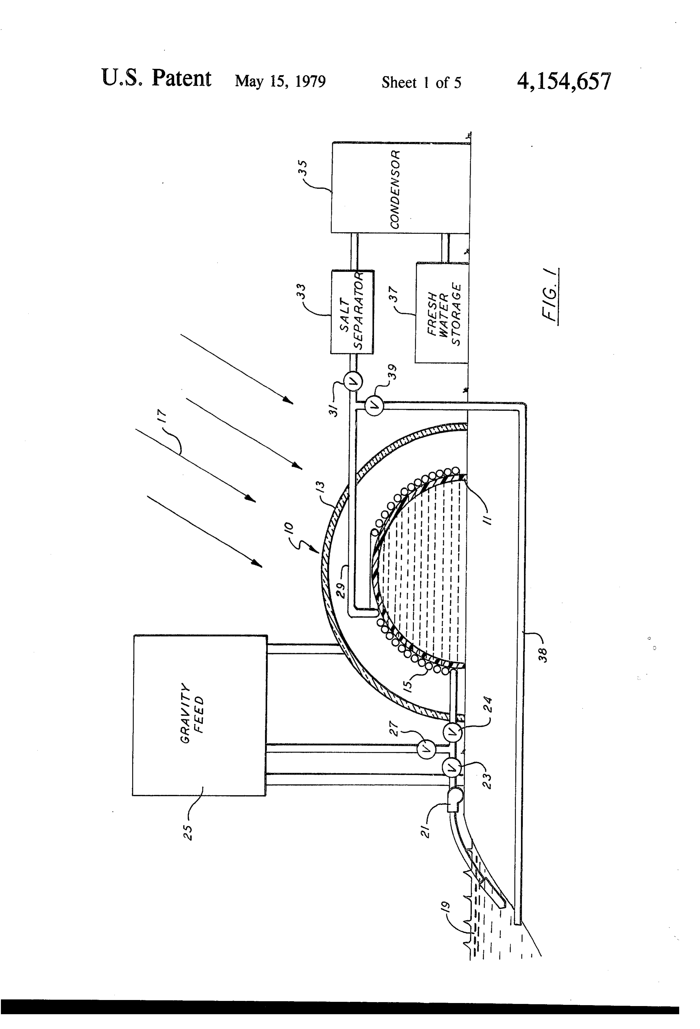
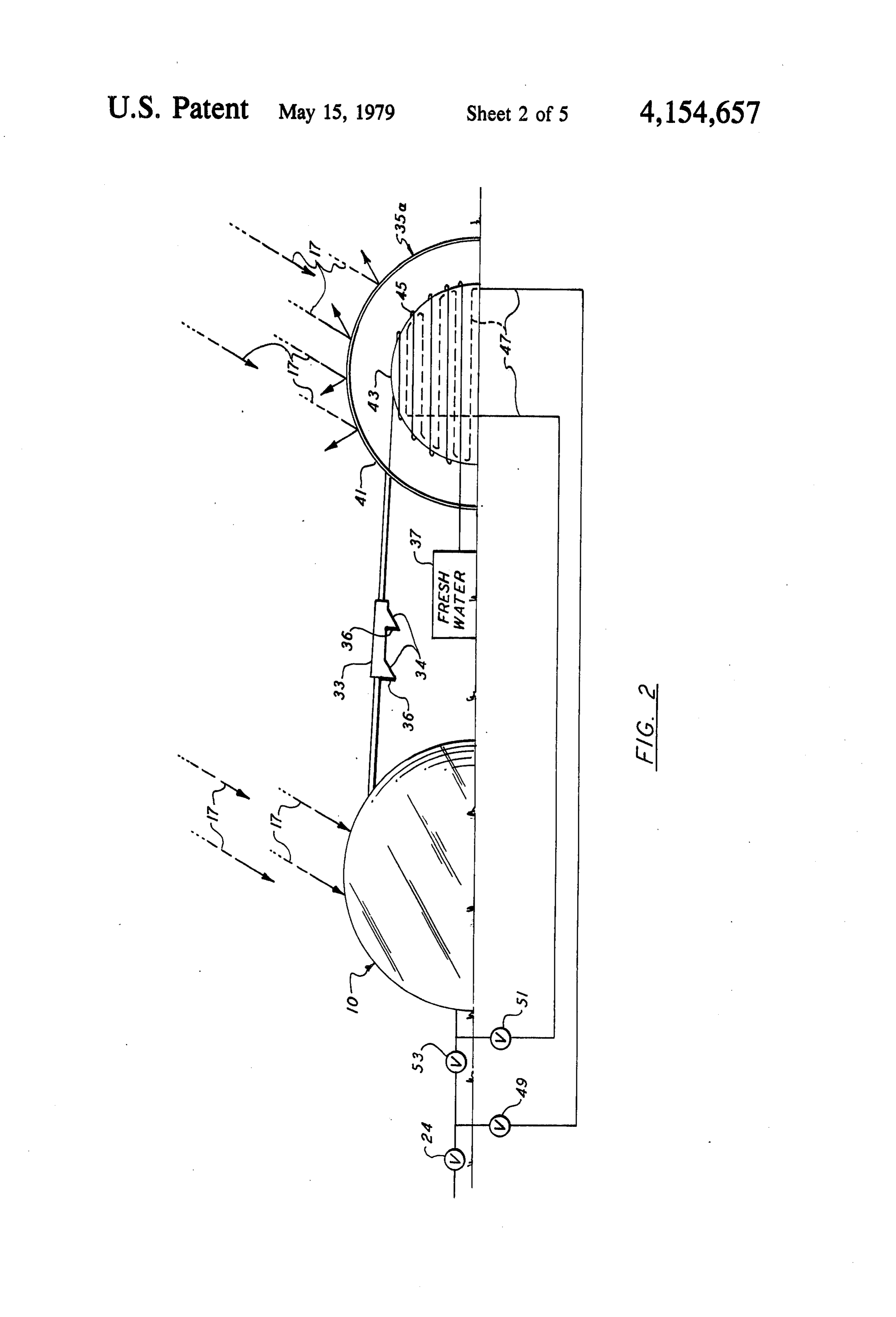
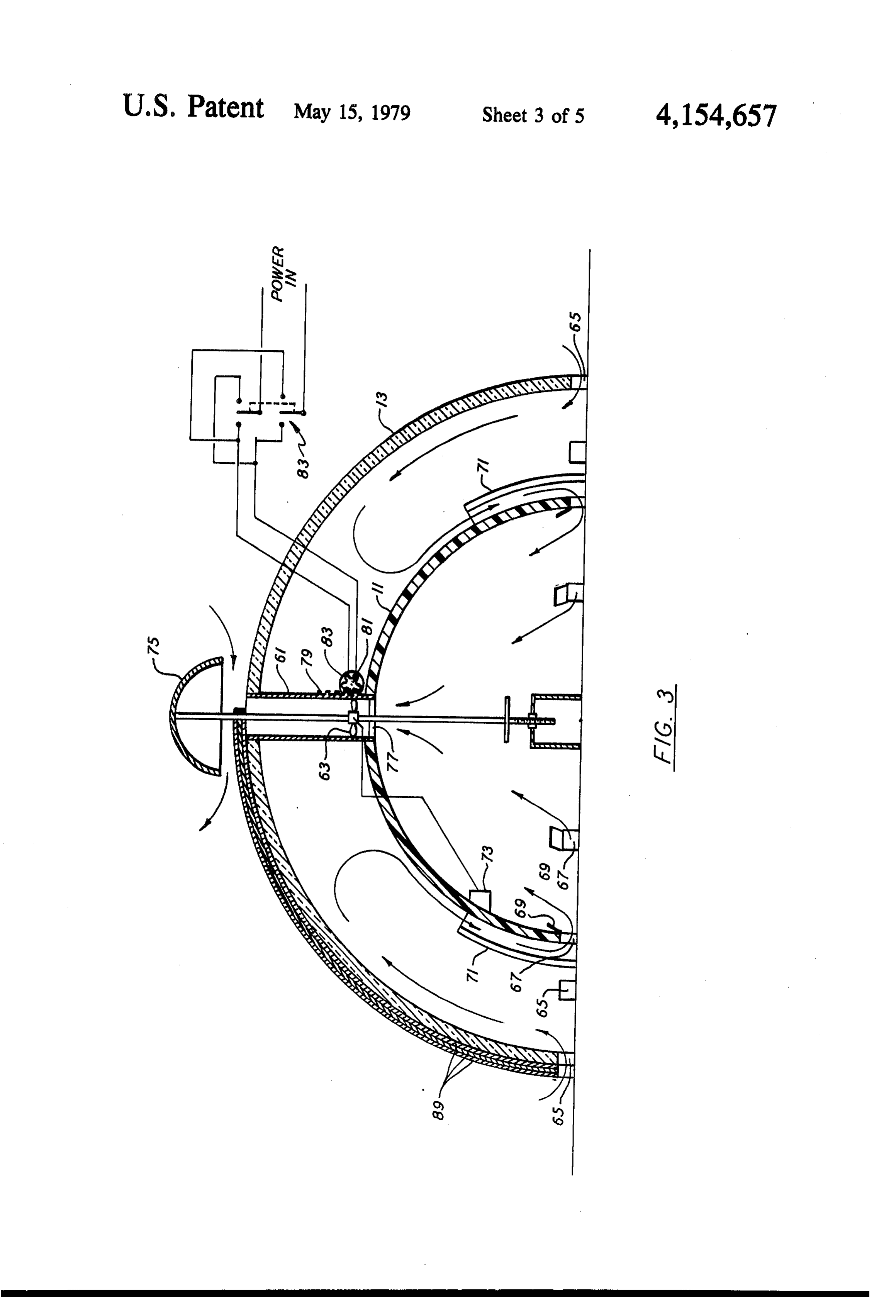
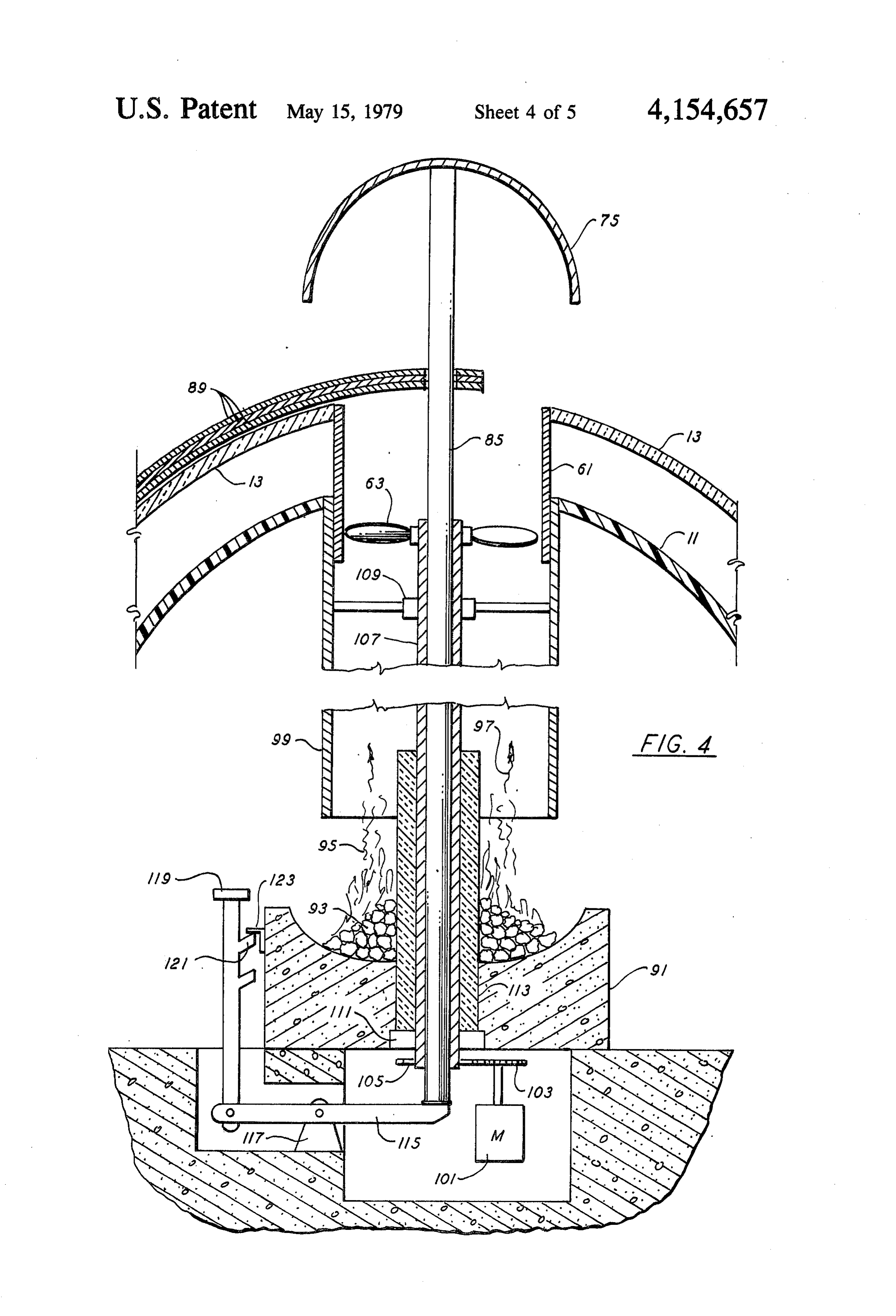
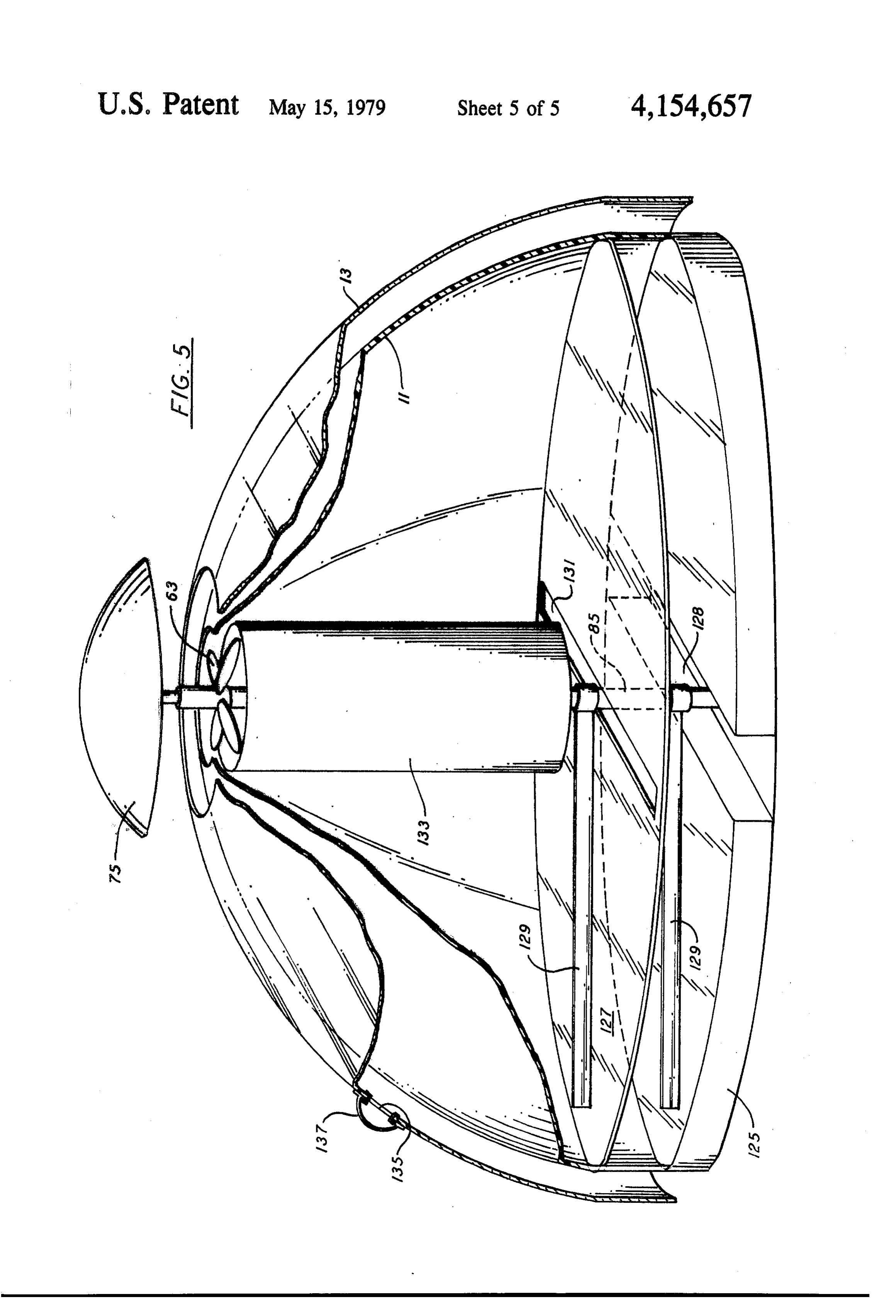
of a highly conductive material such as copper will be 45 BRIEF DESCRIPTION OF THE DRAWINGS extremely expensive.
Thus, although it has been recognized that solar en FIG. 1 is an illustration of a first embodiment of the ergy can be used for converting salt water into fresh present invention used as a desalinization apparatus. water in a desalinization process, the apparatus used in FIG. 2 is a schematic drawing of an installation simi the prior art has been relatively complex and expensive 50 lar to that of FIG. 1 in which the dual dome structure of to build. Thus, the need for an improved type of appara the present invention is also used in implementing a tus which is simple and inexpensive becomes evident. condenser. - -
Attention has also been directed to the use of solar FIG. 3 is a cross sectional schematic view illustrating energy for heating habitable structures. Such use of the application of the dual dome structure of the present solar energy has become particularly important in view 55 invention to form a solar heated habitable space. of the recent energy crisis. Thus, in addition to the need FIG. 4 is a cross-sectional view of further modifica for improved apparatus for desolarization, there is also tions of the structure of FIG. 3. a need for arrangements which permit using solar heat FIG. 5 is a perspective view partially in cross-section for heating habitable spaces. of a structure according to the present invention in the 60 form of a barn.
Summary of the invention
The present invention discloses a dual dome structure DETAILED DESCRIPTION OF THE which finds application both in desalinization and in PREFERRED EMBODIMENT providing a heated habitable space. FIG. illustrates the basic elements of the present The essential elements of the structure are an inner 65 invention. The distillation or evaporating portions of dome of smaller diameter and an outer dome of larger the system comprises an inner hemispherical dome 11 diameter. The outer dome is made of a material such as and an outer hemispherical dome 13 with copper tubing glass which will transmit the sun's rays. Preferably the 15 wound helically around the inner dome 11. The 8 outer dome 13, of necessity must be transparent to per The copper tubing 15 will of course, after some use, mit trapping of the heat generated by the sun's rays contain salt deposits. It will be recognized that the unit between the domes 11 and 13. Preferably the dome 13 can be used only during the daylight hours when suffi will be of glass, in particular, a glass referred to as cient sunlight is available. Thus, a valve 39 is provided Chemcor manufactured by the Corning Glass Com 5 from which a line is directed back to the salt water pany. This glass remains stable at temperatures up to at supply 19. After operation has ceased for the day, valve least 700° C. Although the inner dome can be made of 31 is closed and valve 39 opened. Valve 27 will be any suitable material such as aluminum, stainless steel, closed and valves 23 and 24 open. The pump 21 will or even glass, the preferred material is a polycarbonate then be operated to pump salt water through the piping plastic material such as that known as LEXAN pro 10 15 to wash out the salt deposits therein. Naturally, duced by General Electric and a material known as should of the clogging occur during operation such a flushing system can take place at that time.
VESTEL produced by duPont. Preferably, the inner FIG. 2 shows a system in which the feed water is dome 11 will be non-transparent so that heat will be passed through the condenser prior to being supplied to retained rather than passed through by means of the sun's rays passing through. It is possible to use a trans 15 the evaporating unit 10. It also shows a form of con parent plastic as the outer dome 13, although it is felt denser which uses a structure 35a similar to the evapo rator structure. In this case the condenser 35a comprises that better results will be obtained using a glass such as an outer hemisphere 41 preferably made of plastic and the one mentioned above.
It will be recognized that when speaking of the hemi 20 an inner hemisphere 43 which might be a plastic or glass. Inner hemisphere may also be of highly thermal spherical dome deviations therefrom are also to be con conductive material such as aluminum or steel. Prefera sidered. However, the hemispherical shape or some bly the outer surface of the hemispherical dome 41 will thing quite close thereto e.g. an ellipsoidal or paraboloi have a reflective coating so as to reflect the sun's rays dal segment, is most advantageous since it makes use of 17. In a manner similar to the arrangement of the tubing the sun's rays at all possible angles. Furthermore, it is 25 15, tubing 45 is provided thought that molding such a dome will be simpler than around the dome 43. In thewhich is wound helically illustrated embodiment, a molding some other shape. line 47 inside the dome structure 35a is shown as a dot The primary advantage in using the glass and the ted line. This line contains the feed water obtained from plastic mentioned above is that the distillation chamber the output of valve 24 of FIG. 1 there being installed can be formed in an extremely simple fashion. That is to 30 additional valves 49, 51 and 53. Feed water from valve say, the glass mentioned above along with the plastics 24 is directed through valve 49 with the bypass valve 53 can easily be molded. Thus, once the proper molds are closed. It flows through line 47 inside the dome 43 and set up, and molds of extremely large sizes are possible, back through an open valve 51 to supply the tubing the units can be mass produced in simple fashion. The only copper required in the system is the copper tubing 35 shown on FIG. 1. The relatively cool feed water pass ing under the dome 43 condenses steam in the tubing 45 15. Thus, these units can be mass produced at an excep and at the same time is preheated. This results in more tionally low cost. For the purpose of supplying salt efficient operation.
water to the distillation unit from a salt water source 19 FIG. 2 also illustrates an alternate salt separator 33. In a pump 21 is shown. The pump may either directly this embodiment a unit with troughs 34 closed off by pump water through valves 23 and 24 to the copper 40 hinged doors 36 is used to collect salt carried over by tubing 15 or, alternatively, may be used to fill a gravity the steam.
feed tank 25 which will then supply the salt water to the Of course, in addition to the disclosed cooling system tubing 15 through valves 27 and 24. Salt water passes for the condenser utilizing the feed water on line 47 through the tubing 15 where it is heated by the intense other arrangements can be used. For example, cooling heat which is generated in the space between the two 45 equipment such as an air conditioning unit can be con domes because of the sun's rays to the point where, by tained beneath the dome 43 with the cooled air there the time it reaches the outlet line 29, it is in the form of from directed into the space between the two domes. steam. The steam passes through a valve 31 to a salt Furthermore, if the installation is close to a supply of separator 33 where any salt which is carried over is salt water the condenser could possibly by submerged separated out. The salt separator may take the form, for 50 in the salt water. It should also be noted at this point example, of the salt separating unit disclosed in the that although salt water is spoken of, distillation appara aforementioned U.S. Pat. No. 3,616,270. The steam is tus of the present invention can be used to purify any then directed into a condenser 35 where it is condensed type of unclean water. The significant advantage in this to result in fresh water which is then stored in a fresh type of construction of the condenser is that the same water tank 37, or, should the units be used for irrigation 55 molds which were used to form the structure 10 can purposes directed to appropriate distribution lines for also be used to form the condenser 35a thereby further irrigation purposes or the like if desired. reducing the overall system cost. The condenser 35, can, of course, be of a conven The dual dome of the present invention can also find tional design. For example, condensers such as that application as a solar heated structure. As noted above, shown in any of the aforementioned U.S. Pats. may be the glass and plastic materials can be made in extremely used. In particular, a condenser such as that shown in large sizes. Thus, an igloo type structure comprising the U.S. Pat. No. 3,558,436 in which the salt water supply is dual domes of the present invention and which is heated used for cooling and condensing the steam may be used. by solar heat can be constructed. For example, such a In such a case the feed to the copper tubing 15 of FIG. device might find application as a barn, workshop or 1 would be by way of the condenser 35. As will be well 65 the like. As illustrated on FIG. 3 inner and outer domes recognized by those skilled in the art this results in a 11 and 13 constructed in accordance with FIG. 1 are slight pre-heating of the salt water giving a more effi provided. The domes at their top have a circular cutout cient operation. into which is inserted a duct 61 containing therein a 9 centrifugal fan 63. The outer dome 13 also has a plural 107 and 85 in the vicinity of the fireplace 91 is a layer of ity of air openings 65 at its bottom. The inner dome 11 appropriate insulating 113. Typically the structure will has similar openings 67 which can be covered with be on a base of concrete and in the illustrated embodi hinged flaps 69. These openings are connected to ducts ment a suitable tunnel is made below the fireplace to 71 extending partially up the outside of the dome 11. 5 contain the motor 101 and gears. In addition a lever 115 The fan 63 is coupled to a thermostat 73 which controls pivoted about a fixed pivot 117 and coupled to a rod 119 its operation in conventional fashion. In operation, cool which includes means 121 cooperating with a bracket air enters through the openings 65 and is heated in the 123 fastened to the fireplace 91 is provided for raising space between the two domes whereupon it rises and lowering the rod 85.
toward the top. As heat is required inside the dome 11, 10 FIG. 5 illustrates a specific embodiment of a structure fan 63 is operated to draw the heated air through the in the form of a barn. The construction is basically the ducts 71 and openings 67 into the interior space under same as that described above with the inner and outer neath dome 11. Air is then exhausted out through the hemispheres 11 and 13. Preferably the barn will be built fan 63. By making the inner dome 11 such that it trans on a concrete base 125 and, because of its size will most mits light, this arrangement provides not only a heated 15 probably have to be built in sections, e.g., each hemi and ventilated space but also a lighted space usable sphere will be made up of four or more sections. The during the daylight hours. At other times, the hinge flap sections may be attached to appropriately curved steel 69 can be closed and auxiliary heating equipment used or aluminum supporting members in the shape of an I to heat the space. Even during these periods the dual cross section to which the sections may be bolted. This dome structure acts as an insulator cutting down the 20 will also permit imbedding the ends of the supporting amount of heat which would otherwise be needed. members in the concrete base or in the ground as de Preferably the opening in the top of the dome will sired. The illustrated structure has a raised floor 127 have a cover 75 placed thereover to keep out rain water above the floor formed by the , concrete base 125. A and the like. A screen 77 can be installed at the duct 61 drainage ditch is installed in this concrete floor for or any other appropriate position to keep out flying 25 draining out waste. On both the concrete floor 125 and insects and the like. Rather than using a screen, an ap raised floor 120 rotating cleaning implements 129 are propriate filter may also be used. As illustrated, it is also installed journaled about the central rod 85. Preferably, possible to mount the sleeve or duct 61 for sliding mo the floor 127 will contain a plurality of openings to tion. Shown is rack gear 79 and pinion gear 81 on the permit washing, with the water running down to the end of a motor 83 driven by power switched through a 30 lower floor. Solid material will be scraped by the upper double pole-double throw switch 83. The switch, al scraper 129 and discharged through an opening 131 to though shown schematically on the drawing, will be the drainage ditch. The lower portion of space between appropriately located inside the dome and the operation the two domes can be used for hay storage. In addition, thereof will permit raising and lowering the duct 61. In centrally located and forming the exhaust outlet for the such a case, air can enter between the domes from the 35 structure is a silo 133. It will have appropriate openings top as well as the bottom to improve circulation. Thus, on the bottom and the air exhausted by the fan 63 will it could be opened during the day to improve circula be exhausted through the silo 133 providing excellent tion and closed at night to retain heat. Preferably, the ventilation for it. In addition, the plastic sections can be hood or cover 75 will be mounted on a rod 85 to permit equipped with small openings with a ridge and cap as raising and lowering it so that it can be lowered against shown by the openings 135 and cap 137. Such will be the outer dome 13 to completely enclose the structure. particularly useful in certain areas where sudden de The rod 85 can also perform another function. Since on creases in atmospheric pressure can be experienced. In warmer days it may be desired to reflect heat away, such a case, the covers 137 would pop off to equalize reflecting panels may be provided made of a light the pressure to prevent the structure from exploding or weight reflecting material such as aluminum. These 45 being otherwise structurally damaged. panels may be made so as to be rotatable about the shaft Note also that in FIG. 5 the inner and outer domes 11 85. In the illustrated embodiment, three such panels 89 and 13 have their opening in the same horizontal rather are shown one stacked upon the other. When essentially than vertical plane. In this structure particularly, such full sunlight is desired, these can be so stacked. For can improve the air flow through the space between the example, with only four panels in use, each covering 50 two domes.
90, 270 would be available for sunlight. Thus, a dual dome structure which is particularly FIG. 4 illustrates further modifications of a structure applicable in the use of solar energy for the evaporation such as that shown on FIG. 3. Shown in somewhat of salt water to convert it to fresh water and also for more detail are portions of the reflecting panels 89 rest providing a heated structure has been shown. Although ing on the outer dome 13. Shown specifically is an ad 55 specific embodiments have been illustrated and de vantageous arrangement of the inner pole 85 for raising scribed, it will be obvious to those skilled in the art that and lowering the hood 75. In this arrangement centrally various modifications may be made without departing located within the structure is a fireplace 91. Shown in from the spirit of the invention which is intended to be the fireplace are a plurality of coals 93 which are burn limited solely by the appended claims. ing and emitting flames 95 and combustion gases 97. 60 What is claimed is:
Surrounding the central rod 85 is a chimney 99 which 1. A structure for evaporating salt water usingenergy directs these hot gases to the top of the dome structure. from the sun comprising:
Also shown is a manner of driving the fan 63. Fan 63 is (a) a first dome having a first diameter; driven by a motor 101 coupled through gears 103 and (b) a second dome of a second larger diameter placed 105 to a hollow shaft 107 surrounding the rod 85. As 65 concentrically around said first dome to form a illustrated hollow shaft 107 is supported in suitable closed space between said first and second domes bearings 109 and 111. The fan 63 is rigidly attached to said second dome being of a material which is capa the top of the hollow shaft 107. Surrounding the shafts ble of transmitting solar energy;
Page 10scan →
(c) copper tubing having two ends wound helically (b) means coupled to the other end of said copper around said first dome in the space between said tubing for condensing steam formed therein. first dome and second dome whereby said copper 12. A structure for evaporating salt water using en tubing will be heated to a high degree when ex ergy from the sun comprising:
posed to solar energy to evaporate any salt water 5 (a) a first dome having a first diameter; contained therein; (b) a second dome of a second larger diameter placed (d) means coupled to one end of said copper tubing concentrically around said first dome, said second for supplying salt water thereto at a rate such that dome being of a material which is capable of trans all salt water supplied thereto will be evaporated; mitting solar energy;
(e) means coupled to the other end of said copper 10 (c) a first section of copper tubing wound helically tubing for condensing steam formed therein; and around said first dome in the space between said (f) means coupled to said tubing to permit connecting first dome and second dome whereby said copper said other end of said tubing to a discharge line tubing will be heated to a high degree when ex thereby permitting water to be passed through said 15 posed to solar energy;
tubing and said discharge line to flush out salt de (d) a third dome having a third diameter; and posited within said copper tubing. (e) a fourth dome having a diameter larger than said 2. Apparatus according to claim 1 wherein said con third dome, a second section of copper tubing densing means comprise: wound helically around said third dome and cou (a) a third dome having a third diameter; and pled in series with said first section of copper tub (b) a fourth dome having a diameter larger than said 20 ing, said fourth dome being constructed so as to not third dome, said fourth dome being constructed so pass solar energy by reflecting it and said third as to not pass solar energy by reflecting it and said dome constructed so as to transmit any energy third dome being constructed so as to transmit any which reaches it to the ground, said third and energy that reaches it to the ground to be conveyed 25 fourth domes and said second section of tubing away, and a second section of copper tubing acting to condense steam formed in said first sec tion.
wound helically around said third dome and cou 13. Apparatus according to claim 12 wherein said pled in series with said section of copper tubing third dome is made of glass in order to better absorb would helically around said first dome. energy reaching it and transmit it to the ground and said 3. Apparatus according to claim 1 and further includ 30 fourth dome made of plastic and exteriorly reflective so ing means for storing the fresh water condensed in said as to reflect away as much solar energy as possible. means for condensing. 14. Apparatus according to claim 12 wherein said 4. Apparatus according to claim 1 and further includ first dome is made of glass transparent to the sun's rays ing means interposed between said other end of said to permit passage of solar energy therethrough and said tubing and said condensing means for separating out salt 35 second dome of plastic so as to retard transmission of carried along with said steam. energy therethrough.
5. Apparatus according to claim 1 wherein said means 15. Apparatus according to claim 4 and further in for supplying salt water to said tubing comprises at least cluding means coupled to said tubing to permit connect a pump and wherein said means coupled to said other ing said other end of said tubing to a discharge line end comprise valve means for selectively coupling said thereby permitting water to be passed through said other end of said tubing to said discharge line. tubing and said discharge line to flush out salt deposited 6. Apparatus according to claim 5 and further includ within said copper tubing.
ing a gravity feed tank between said tubing and said 16. A structure for evaporating salt water using en pump. ergy from the sun comprising: 7. Apparatus according to claim 6 and further includ 45 (a) a first dome having a first diameter; ing means directing the water supplied to said tubing (b) a second dome of a second larger diameter placed through said condensing means prior to being supplied concentrically around said first dome to form a to said copper tubing. closed space between said first and second domes, 8. Apparatus according to claim 4 wherein said means said second dome being of a material which is capa for separating salt comprises a unit having at least one 50 ble of transmitting solar energy; trough and a hinged door for emptying said trough. (c) copper tubing having two ends wound helically 9. Apparatus according to claim 8 wherein said third around said first dome in the space between said dome is made of glass in order to better absorb energy first dome and second dome whereby said copper reaching it and transmit it to the ground and said fourth tubing will be heated to a high degree when ex dome made of plastic and exteriorly reflective so as to 55 posed to solar energy to evaporate any salt water reflect away as much solar energy as possible. contained therein;
10. Apparatus according to claim 9 wherein said first (d) means coupled to one end of said copper tubing dome is made of glass transparent to the Sun's rays to for supplying salt water thereto at a rate such that permit passage of solar energy therethrough and said all salt water supplied thereto will be evaporated; second dome of plastic so as to retard transmission of 60 (e) means coupled to the other end of said copper energy therethrough. tubing for condensing steam formed therein; and 11. Apparatus according to claim 8 and further in (f) means interposed between said other end of said cluding: tubing and said condensing means for separating (a) means coupled to one end of said copper tubing out salt carried skalong with said steam.
for supplying salt water thereto; and 65
Page 11scan →
United states patent and trademark office
Certificate of correction
INVENTOR(S) : Nancy L. Dennen
It is certified that error appears in the above-identified patent and that said Letters Patent are hereby Corrected as shown below:
Col. 6, line 2 change "insulating" to -- insulation -- Col. 6, line 23, after "by the" delete -- comma -signed and Sealed this
Eleventh Day of September 1979.
Seal
Attest:
Lutrelle f. parker
Attesting Officer Acting Commissioner of Patents and Trademarks
Provenance
- Collection
- Patents citing this work
- Pages
- 11
- Method
- pdftotext (the PDF's own text layer) + pdftoppm 300dpi page scans
- Patent office record
- patents.google.com →
- Source
- Google Patents citing-documents table
- Assignee
- Dennen Nancy L
- Published
- 1979-05-15
- Transcribed from
- patentimages.storage.googleapis.com →