

patent · US4170200A
Internal combustion engine with reformed gas generator
9 October 1979
Text
Page 1bibliographic recordscan →
United States Patent (19)
Takeuchi et al.
54 INTERNAL COMBUSTION ENGINE WITH
REFORMED GAS GENERATOR
(75) Inventors: Yukihisa Takeuchi, Aichi; Kouji
Horie, Kariya, both of Japan Assignee: Nippondenso Co., Ltd., Cichi, Japan
Related U.S. Application Data 62 Division of Ser. No. 583,763, Jun. 4, 1975, abandoned. (30) Foreign Application Priority Data
Jun. 14, 1974 JP Japan .................................. 49/68580 Jul. 31, 1974 JP Japan .................................. 49/88268 Sep. 1, 1974 (JP) Japan ................................ 49/1001.92
52 U.S. C. ..................................... 123/3; 48/197 R;
A/7 AEAO
3,717,129 2/1973 Fox ................... ... 23/DIG. 12 3,801,708 4/1974 Smith ................................... 252/373
3,971,847 7/1976 Houknan .............................. 252/373 Primary Examiner-Charles J. Myhre
Assistant Examiner--David D. Reynolds
Attorney, Agent, or Firm-Cushman, Darby & Cushman
The invention discloses an internal combustion engine of the type in which alcohol or alcohol-containing mix ture and air undergo the thermal or catalytic reforming reaction, and the reformed gases containing hydrogen are directly charged or mixed with gasoline or the like and charged into the engine for combustion. The pro duction of soot and tar during the thermal or catalytic reforming reaction may be minimized, and the emission of noxious combustion products may be also minimized. 10 Claims, 11 Drawing Figures
Drawings
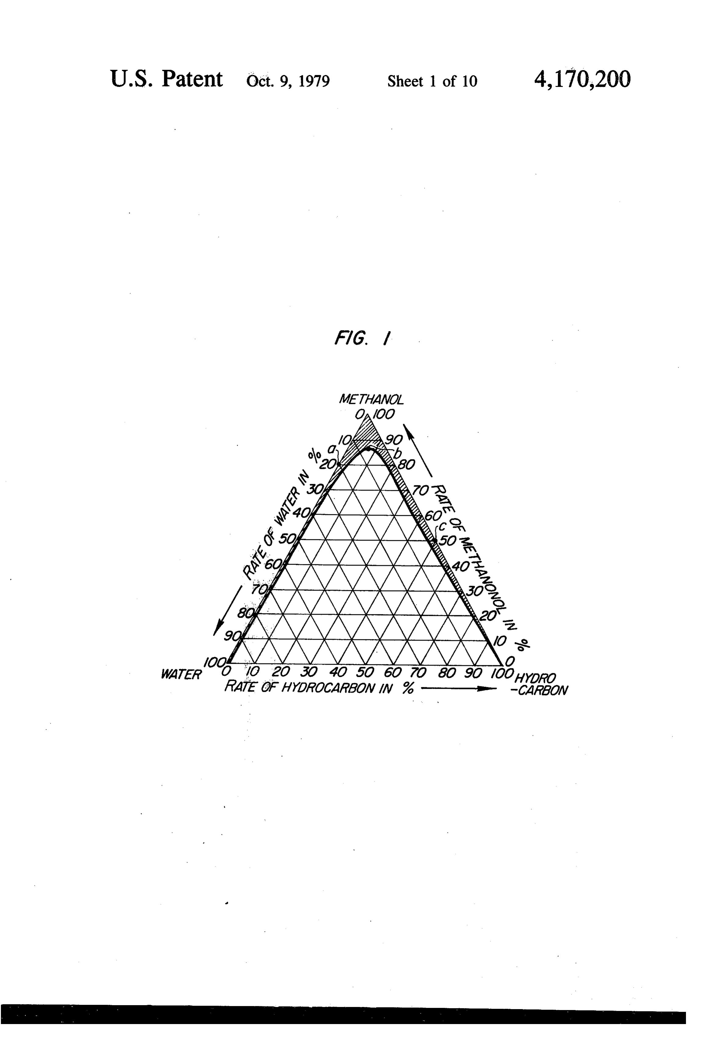
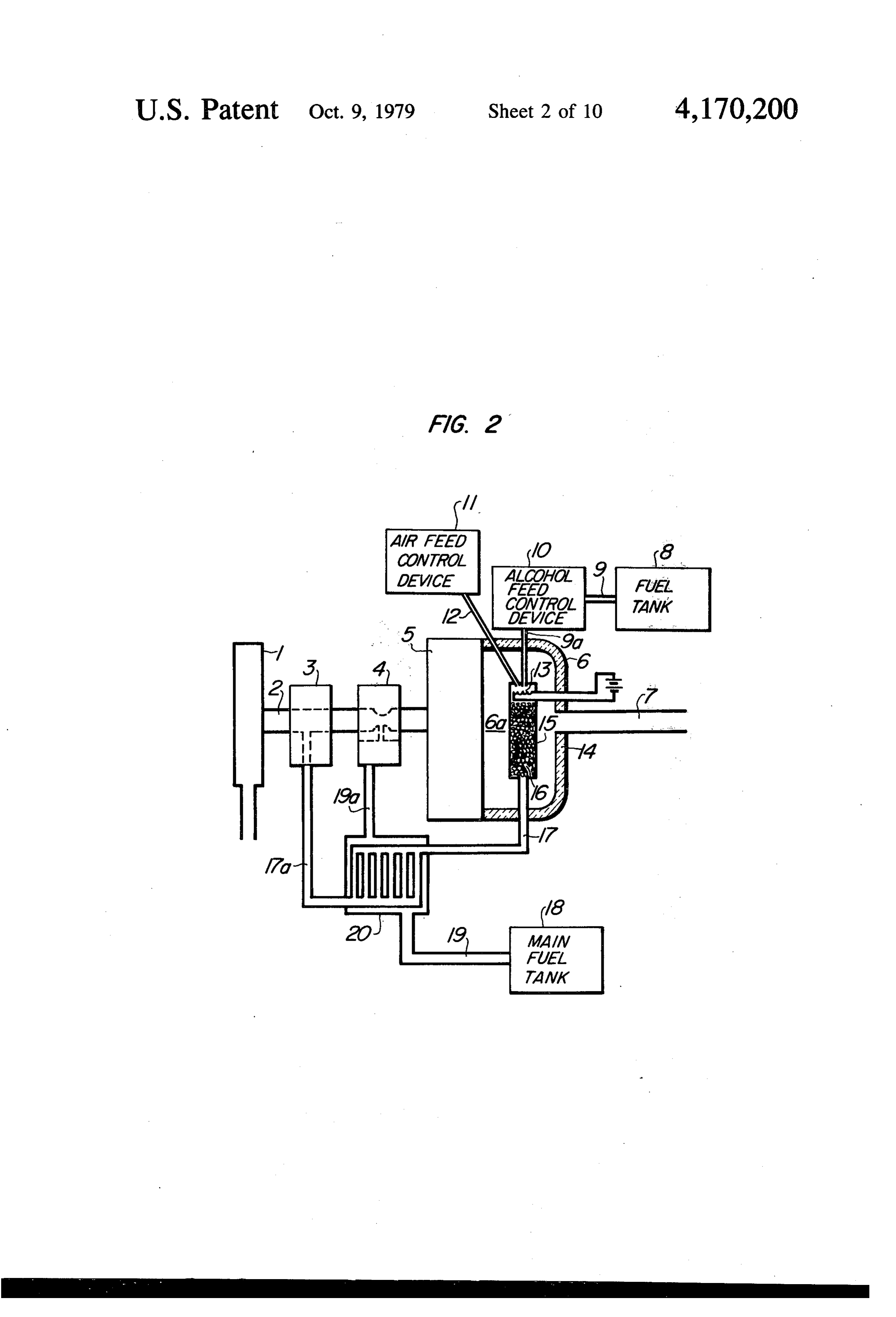
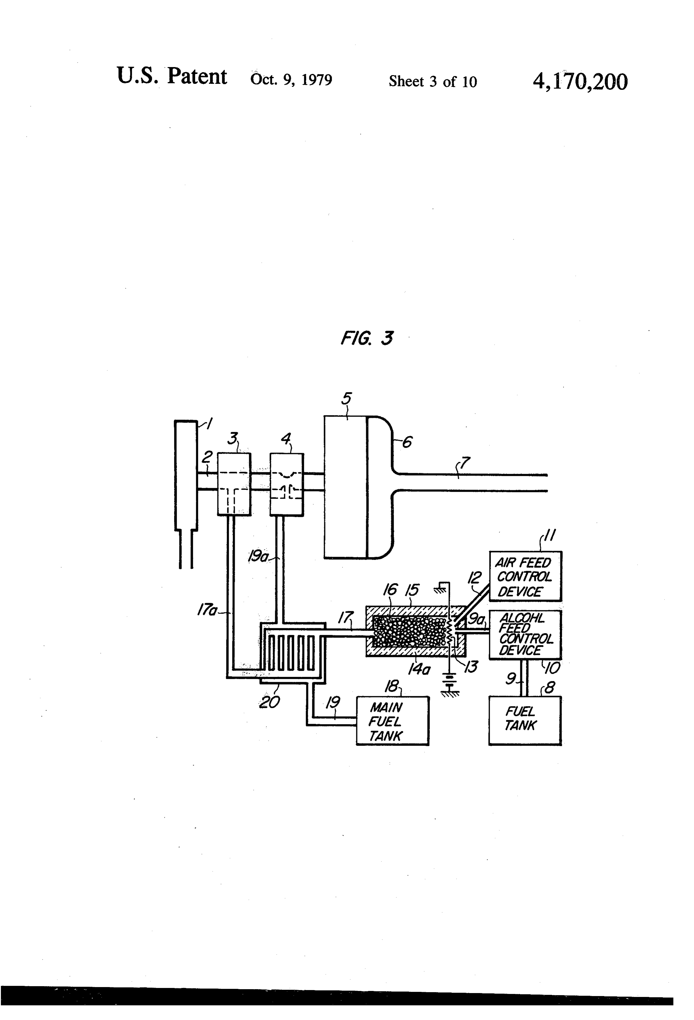
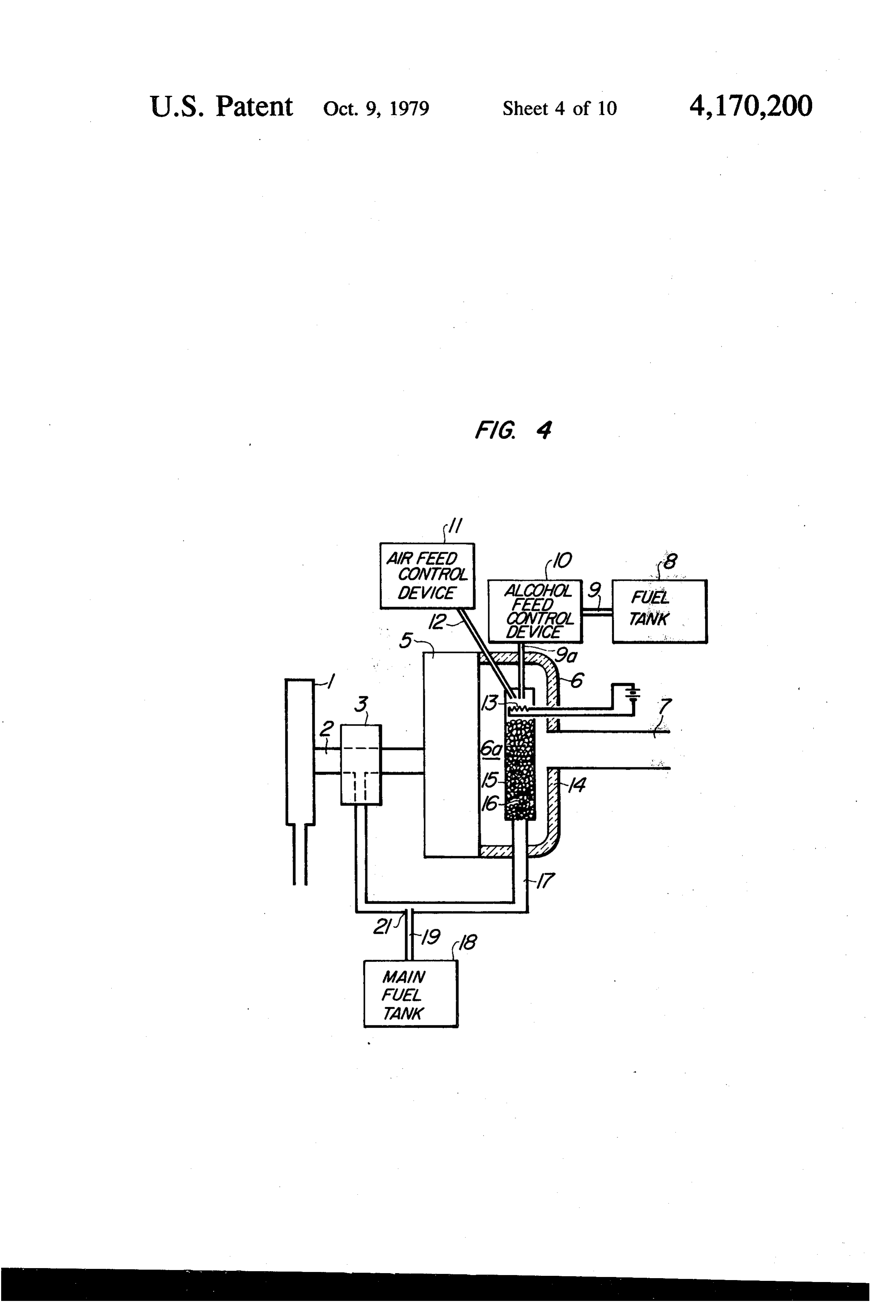
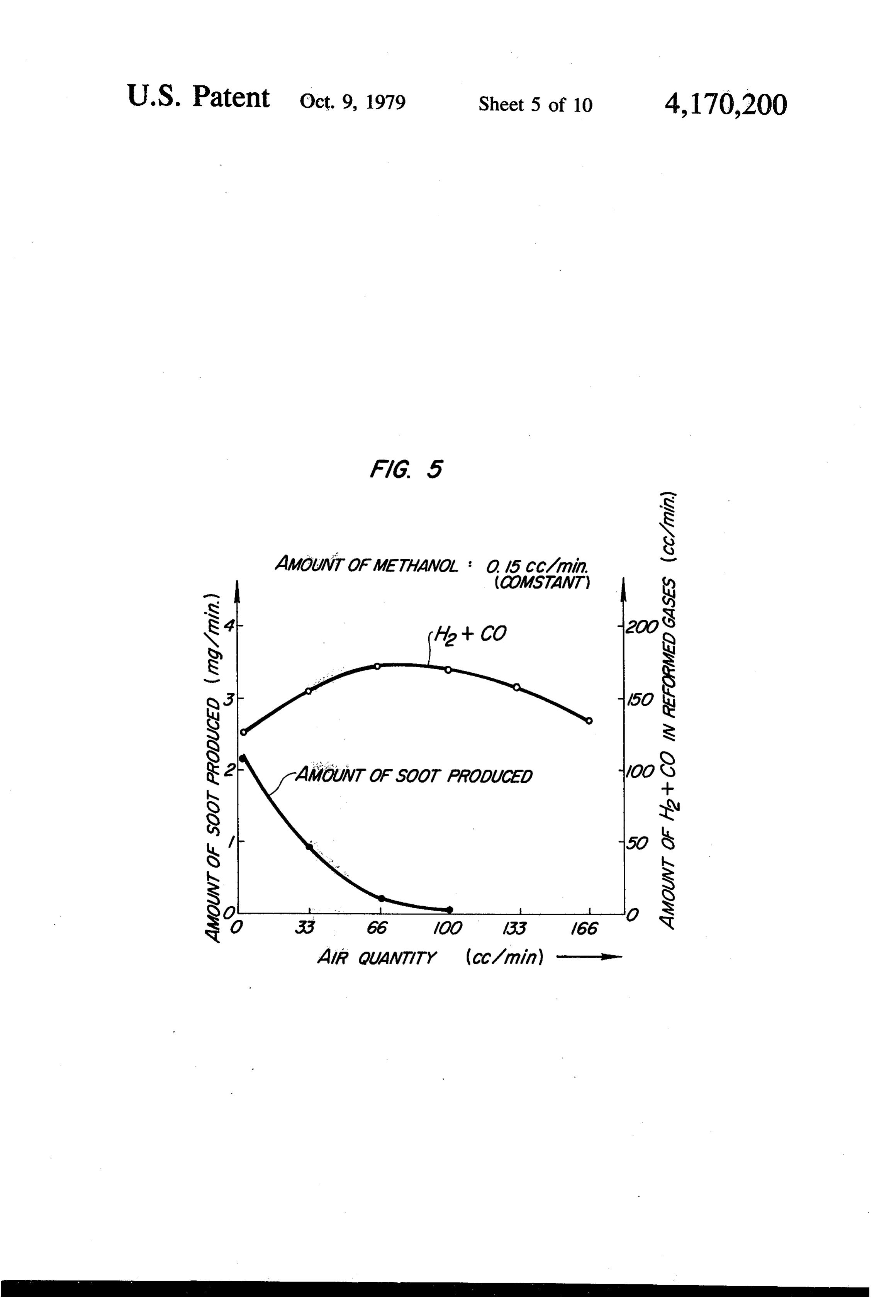
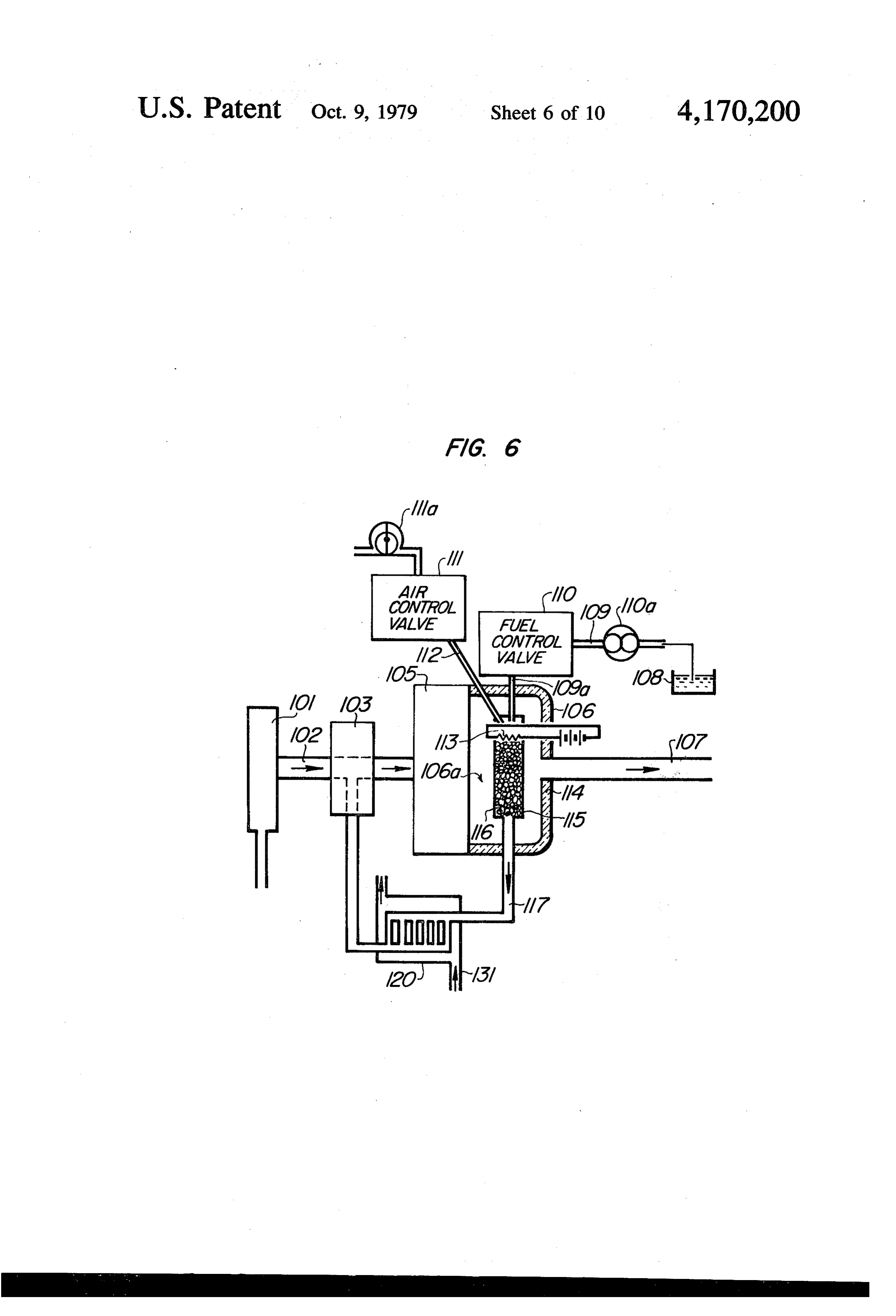
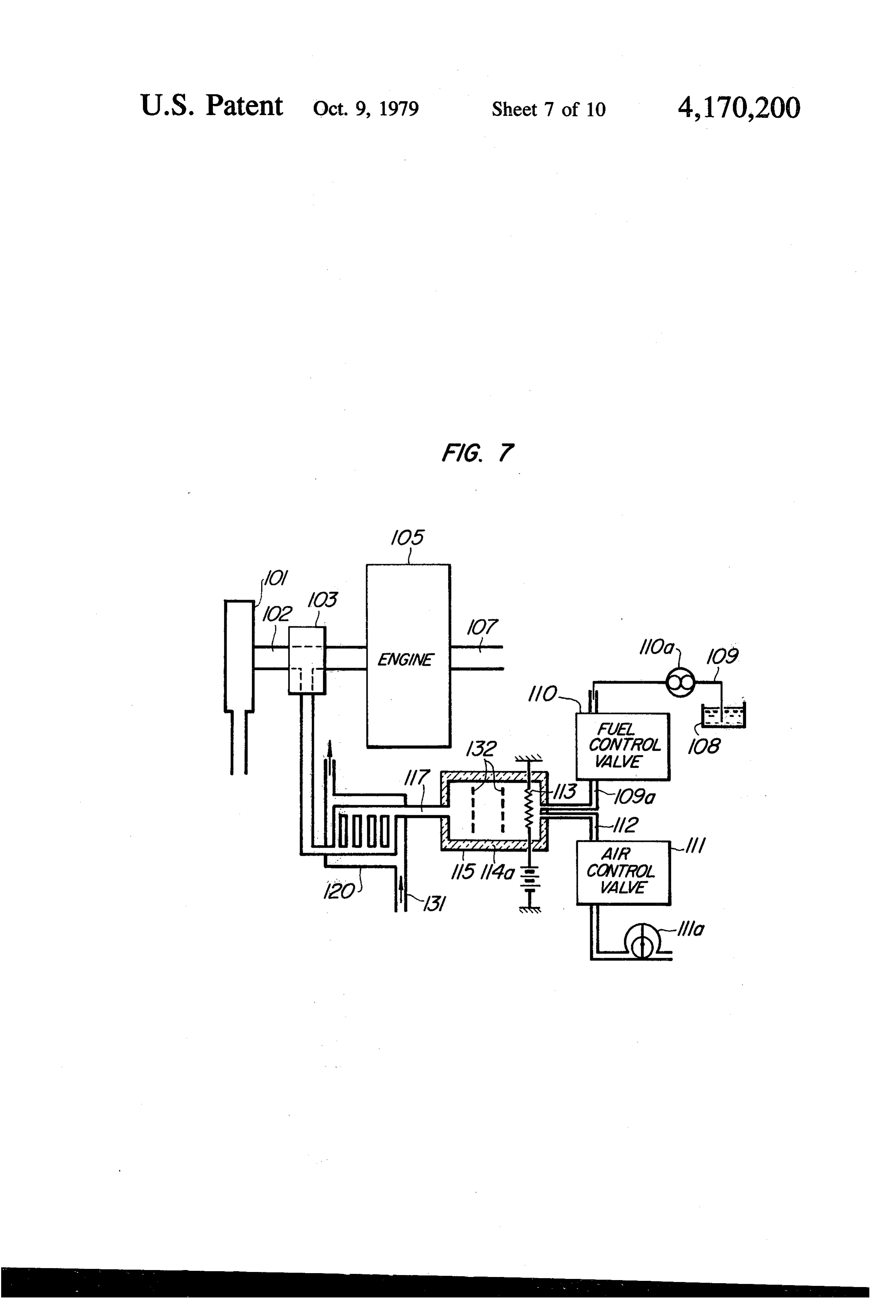
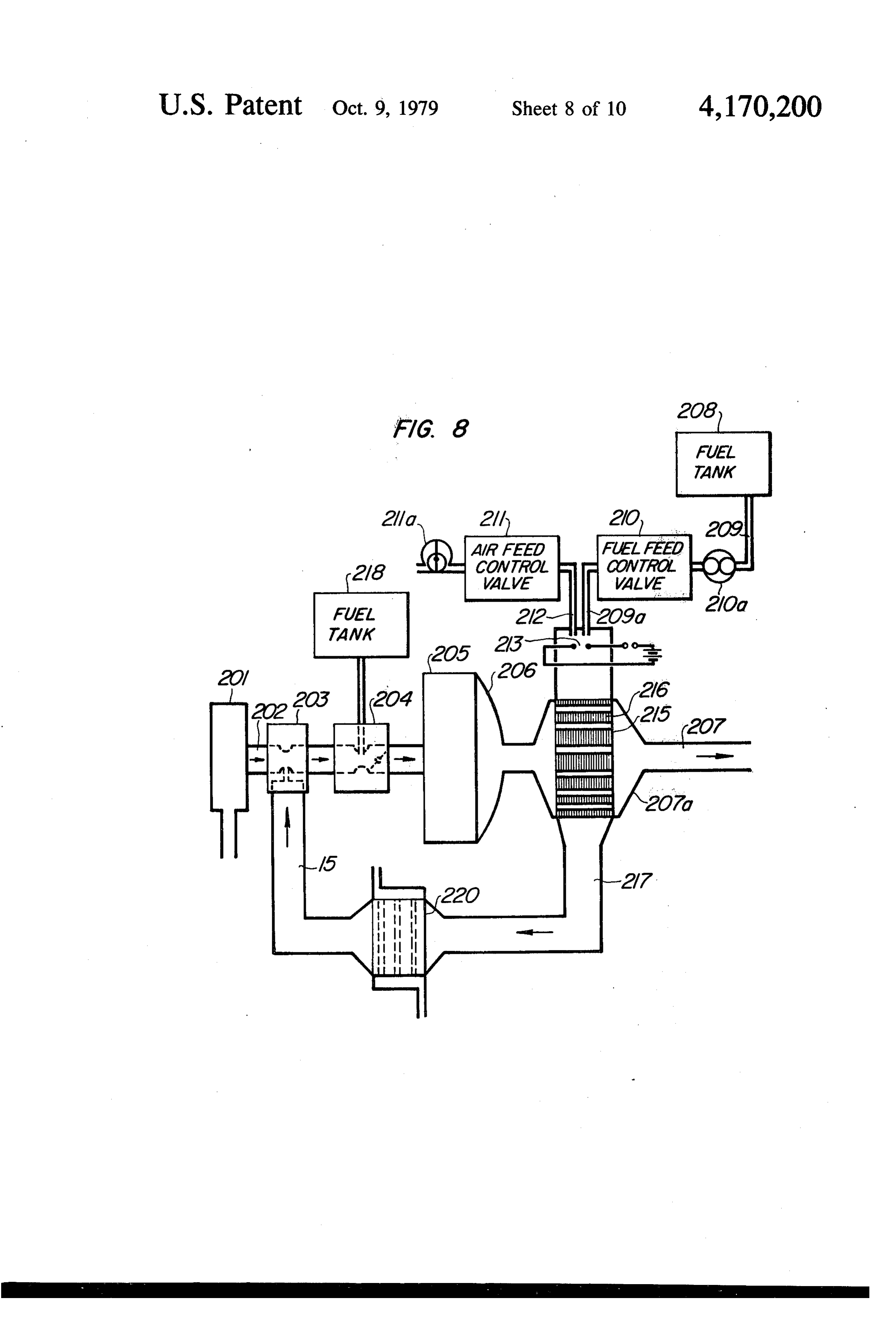
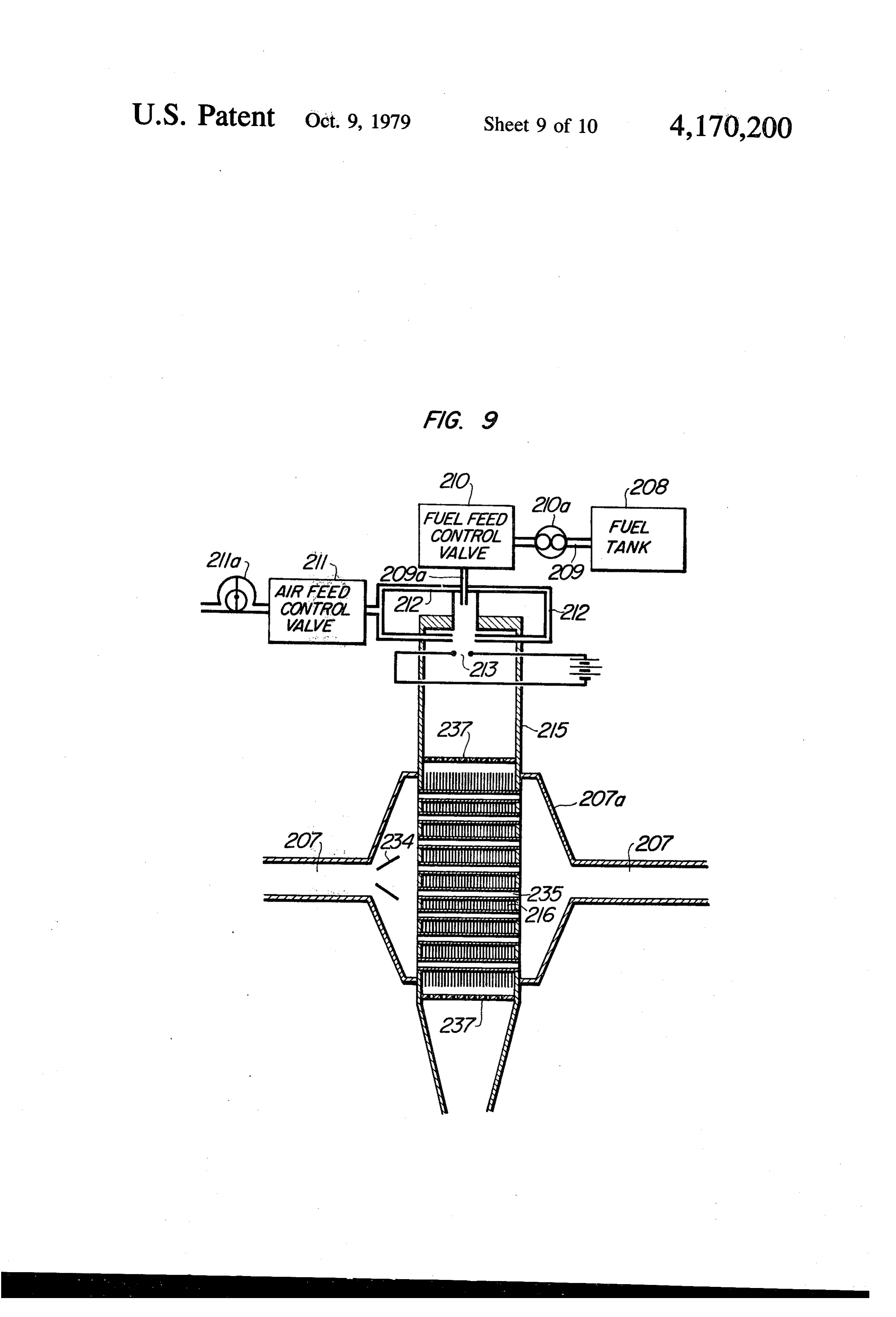
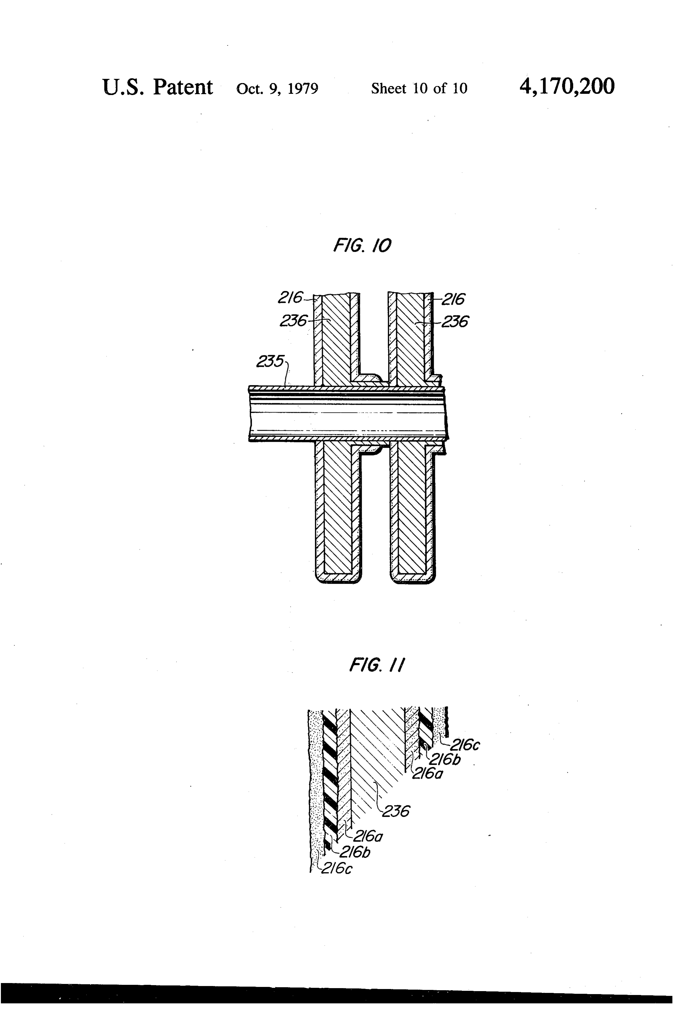
FIG. 11 is a schematic diagram, on further enlarged and the like or when the hydrocarbon fuel contains scale, of part of a catalyst unit thereof used for the gum, soot and tar are deposited upon the surfaces of the construction thereof.
Page 2drawing sheetscan →
Page 3drawing sheetscan →
Page 4drawing sheetscan →
Page 5drawing sheetscan →
Page 6drawing sheetscan →
Page 7drawing sheetscan →
Page 8drawing sheetscan →
Page 9drawing sheetscan →
Page 10drawing sheetscan →
Page 11drawing sheetscan →
Page 12scan →
that the emission of the noxious combustion products
NTERNAL COMBUSTION ENGINE WITH may be considerably reduced. According to the present REFORMED GAS GENERATOR invention, the chemical catalytic process of the hydro carbon fuel is not carried out in order to produce the
This is a division, of application Ser. No. 583,763 reformed gases so that no soot and tar are produced. abandoned filed June 4, 1975. Therefore, the problems of the contamination' of the BACKGROUND OF THE INVENTION catalyst and of clogging of the fuel supply pipe by the soot and tar may be eliminated.
The present invention relates to an internal combus tion engine combined with a reformed gas generator for 10 BRIEF DESCRIPTION OF THE DRAWINGs the purpose of minimizing the emission of the noxious FIG. 1 is a solubility diagram of methanol, water and combustion products. hydrocarbon used in the internal combustion engine in In the conventional internal combustion engines com accordance with the present invention; bined with a reformed gas generator, the mixture of FIG. 2 is a schematic diagram of a first embodiment hydrocarbon fuel such as gasoline, air, water and ex 15 of the present invention;
haust gases from the engine is passed through a reactor FIG. 3 is a schematic diagram of a first modification packed with catalysts and heated at a temperature be of the first embodiment;
tween 250 and 1,000 C. so that a part of the fuel may be FIG. 4 is a schematic diagram of a second modifica converted into hydrogen and/or carbon monoxide be tion of the first embodiment; w fore the combustion mixture is charged into the com 20 FIG. 5 shows a graph illustrating the relationship bustion chambers of the engine. There has been also among the air quantity fed into a reforming reactor, the devised and demonstrated an internal combustion en amount of hydrogen and carbon monoxide produced by gine of the type in which hydrogen supplied from a hydrogen storage tank is mixed with the hydrocarbon the reforming reaction, and the amount of soot pro duced;
fuel. In the engines of the former type, an independent 25 FIG. 6 is a schematic diagram of a second embodi water tank must be mounted so that there is a fear that the water tank may rupture when water is freezed. ment of the present invention; When the fuel contains lead compounds, the exhaust thereof; 7 is a schematic diagram of one modification gases inevitably contains the lead compounds so that the catalysts are contaminated or poisoned by the lead 30 ofFIG. 8 is a schematic diagram of a third embodiment the present invention;
compounds. Even when the fuel does not contain the FIG. 9 is a detailed view, on enlarged scale, of a lead compounds, soot and tar in the exhaust gases con reactor thereof;
taminate the catalysts. Therefore in either cases, the FIG. 10 is a fragmentary view, on still enlarged scale, catalytic activity is lost. When the fuel is a cyclic hydro carbon compound such as gasoline, light oil, kerosine 35 thereof; and
FIG. 11 is a schematic diagram, on further enlarged and the like or when the hydrocarbon fuel contains scale, of part of a catalyst unit thereof used for the gum, soot and tar are deposited upon the surfaces of the construction thereof.
catalysts, the inner wall of the reactor and the inner wall of the fuel supply pipe connecting the reactor with the DESCRIPTION OF THE PREFERRED engine so that the catalytic activity is lost and the clog EMBODIMENTS ging of the fuel pipe occurs. In the internal combustion First Embodiment, FIGS. 1 through 5 engines of the type in which hydrogen is supplied from a hydrogen storage tank, there is a fear that the storage Referring first to FIG. 2, an air cleaner 1 is connected tank might explode itself. Furthermore, the hydrogen to an engine block 5 through an intake pipe 2, a mixing storage tanks are, in general, large in size and heavy in 45 chamber 3 in which the reformed gases are mixed with weight so that mounting them on the automotive vehi the intake air, and a carburetor 4. Instead of the carbure cles results very serious economical disadvantages. tor 4, any suitable fuel injection system may be em
Summary of the invention
ployed. The exhaust gases from the engine block 5 flows into an exhaust gas chamber 6a defined by a cas
One of the objects of the present invention is there 50 ing 6 and then into an exhaust pipe 7. A fuel tank 8 fore to provide an internal combustion engine with a containing alcohol or alcohol containing mixture is reformed gas generator which may substantially elimi connected to a reforming reactor 15 through a pipe 9, nate the difficulties encountered in the conventional an alcohol feed control device 10 and a pipe 9a. The internal combustion engines. alcohol feed control device 10 controls the quantity of Briefly stated, the present invention provides an in 55 alcohol or alcohol-containing liquid to be supplied to ternal combustion engine combined with a reactor for the reactor 15 in response to the engine operating condi causing the thermal or catalytic reforming reaction of tions. An air feed control device 11 is communicated alcohol or alcohol-containing mixture with air with the through an air pipe 12 with the reactor 15 in order to utilization of heat thereby converting into reformed charge into the reactor 15 the air the quantity of which gases containing hydrogen, and a reformed gas charg- 60 is to 1/15 of the intake air quantity. At the upper end ing system for charging the reformed gases into the portion within the reactor 15 is located an electrical combustion chambers of the engine. ignition or heating device 13 consisting of a nicrome or According to the present invention, the problem of tantalum wire or a spark or glow plug. The casing 6 is aging of the catalysts may be overcome; the use of a lined with an insulating layer 14 in order to keep the hydrogen storage tank large in size and heavy in weight 65 high temperature in the exhaust chamber 6a. The reac may be eliminated; and the lean combustion mixture in tor 15 is filled with catalyst 16 for accelerating the air-fuel ratio considerably lower than the theoretical chemical reaction between air and alcohol. The reac air-fuel ratio may be satisfactorily burnt in the engine so tion products or gases from the reactor 15 flow through 13 a pipe line 17 into a heat exchanger 20 in which the heat upon the catalyst used, the composition of the product is exchanged between the reaction products or re of the catalytic reforming process, the volume thereof, formed gases and the main fuel supplied from a main the temperature at which the catalytic reforming pro fuel tank 18 through a fuel pipe line 19. cess may proceed in a stable manner, and the quantity of The ignition or heating device 13 starts the catalytic soot produced are different slightly. The most effective reforming reaction within the reactor 15 between the catalysts are platinum- and nickel-containing catalysts. air charged through the air feed control device 11 and The catalytic reforming reaction proceeds at a tempera alcohol or alcohol-containing mixture supplied through ture higher than 250 C., but the reaction temperature is the alcohol feed control device 10 so that the reformed preferably 300° C. to 700° C. because the reformed gases are produced. The heat generated by the reform 10 gases must pass through the heat-exchanger 20 to give ing reaction serves to raise the temperature of the cata their heat to gasoline in order to facilitate the atomiza lyst 16 immediately after the engine is started. After the tion and evaporation thereof. Because of the energy temperature of the exhaust gases rises above 500 C., the loss, the air feed to the reactor 15 is preferably about catalytic reforming reaction proceeds by the heat of the 100 cc/min. that is, about 10% of the air quantity re exhaust gases so that the ignition or heating device 13 15 quired for the stoichiometric combustion of alcohol in may be de-energized. order that the reformed gases in desired composition In the heat exchanger 20, the reformed gases are may be produced.
cooled to a desired temperature while the fuel from the From Table 1, it is seen that the use of methanol is main fuel tank 18 is heated. Therefore, the mixture ratio most advantageous because hydrogen and carbon non between the reformed gases and intake air may be main 20 oxide are produced in large quantity. Furthermore, tained constant, and the atomization and evaporation of there is another advantage in that almost no soot and tar the fuel from the main fuel tank 18 may be much facili deposit on the catalysts. When ethanol undergoes the tated. The reformed gases flow from the heat exchanger catalytic reforming process, in addition to hydrogen, 20 through a pipe 17a into the mixing chamber 3 where carbon monoxide and methane, various compounds the reformed gases are mixed with the intake air. The 25 having a higher number of carbon atoms such as ethane, main fuel flows from the heat-exchanger 20 through a ethylene, acetylene, propylene and the like are pro fuel pipe 19a into the carburetor 4 in such a quantity duced, and soot is attached to the catalyst even though that the air-fuel ratio lower than the stoichiometric ratio in a very small quantity. In order to reduce the reaction may be obtained. The combustion mixture consisting of products having a higher number of carbon atoms, the the main fuel, the reformed gases and the air is charged 30 air feed may be increased up to 15% of the air quantity into the engine block 5 for combustion. required for the stoichiometric combustion of alcohol, When the volumetric ratio between the main fuel or but the increase over 15% is not preferable because the gasoline and the reformed gases in terms of methanol is, energy loss is considerably increased for the practical for instance, 1:5, the stable combustion may be ensured purpose. In summary, the air feed quantity must be so even when the air-fuel ratio of gasoline is higher than 20 35 selected that almost no soot may be attached to the (1.3 in terms of the excess air ratio). The engine output catalyst. Most preferably the air feed quantity is about reduction is negligible, and even immediately after the 15% in weight of the air quantity required for the stoi engine is started, the contents of noxious combustion chiometric combustion of methanol as shown in FIG. 5. products such as nitrogen oxides, carbon monoxide, In FIG. 5, air feed is 100 cc/min. for alcohol feed of 0.15 hydrocarbons and so on in the exhaust gases are consid 40 cc/min. When the energy loss is taken into consider erably reduced. The ratio between the reformed gases ation, the catalytic reforming reaction is expressed as in terms of methanol and gasoline may be reduced as follows:
low as 1:8, but it is preferable to change this ratio de pending upon the air-gasoline ratio.
Table 1 below shows the composition of the products 45 of the catalytic reforming process in the reactor 15.
Table 1
Air gases Carbon Carbon Water
Alcohol cc/min. cc/min. Hydrogen Nitrogen monoxide Methane dioxide Residue cc/min.
Methanol 100 305 0.015
Ethanol 100 305 0.013
Reaction Conditions:
Temperature: 500' C
Catalyst: Pt - Al2O3
Alcohol Feed: 0.15 ccAmin.
The laboratory experiments showed that the composi tion of the products of the catalytic reforming process remains almost same.
As the catalyst 16, any conventional catalysts con- 65 This is an endothermic reaction absorbing heat of 120 taining oxides of Pt, Pd, Ni, Co, Fe, Cu, Or, Au and so Kcal/Mol. When the air feed is increased beyond 15%, on or the so-called ceramic compounds such as Al2O3, the exothermic reaction takes place, resulting in the SiO2, MgO, CaO and the like. However, depending reduction of hydrogen and carbon monoxide.
Page 14scan →
Water produced by the catalytic reforming reaction gasoline and attached on the catalyst becomes so that and charged into the combustion chambers not only the catalytic activity is lost. Therefore, the maximum reduce the temperature in the combustion chambers but allowable mixture ratio between methanol and gasoline also serves to reduce the formation of nitrogen oxides. is 7:3. Within this ratio, even when 2% in volume of However, care should be taken that a large quantity of 5 water in the atmosphere is absorbed by methanol, meth water may not be produced because it causes the erro anol and gasoline will be separated from each other into sion of the engine and reduces the engine output. two layers.
Table 2 shows the composition of the products of the Next referring to FIG. 3, one modification of the first catalytic reforming reaction of (a) the mixture of 80% embodiment will be described. The construction is sub of methanol and 20% of water, (b) the mixture of 86% 10 stantially similar to that of the first embodiment except of methanol, 7% of water and 7% of hydrocarbon and that the catalytic reforming reaction proceeds not by (c) the mixture of 50% of methanol and 50% of hydro the heat of the exhaust gas but by the heat generated by carbon. the ignition or heating device 13. This construction has Table 2
Composition in % - Reform
Metha- Hydro- Air feed ed gas Composition in % and cc/min. Mixture nol Water carbon ccanin, ccdmin. H2 N2 CO CH4 CO2 C2H4 Residue 37.0%. 33.5 13.5 0.5 45 0.5 1.5 cc/min 80 33 26 11 4.
37.0%. 360. 17.5 3.3 7.0 - 1.0 cc/min. 80 39 4. 15' 0.5 2.5
In these mixtures (a), (b) and (c), water, methanol and an advantage in that the reactor 15 may be located in a hydrocarbon are not separated from each other and position remote from the engine block so that the dam well mixed as shown in the hatched area of the solubil ages to the catalyst due to the vibration of the engine ity diagram shown in FIG. 1. The hydrocarbon used block may be prevented. has the composition similar to that of the ordinary gaso Another modification of the first embodiment shown line, and its cyclic hydrocarbon compound (especially 35 in FIG. 4 is also substantially similar in construction to aromatic compounds) and gum contents are very small the first embodiment shown in FIG. 2 except that gaso (less than 2 to 3%). From Table 2 it is seen that the line is directly injected into the reformed gases by gaso volume of hydrogen, carbon monoxide and methane line injecting means 21. This modification has a distinct produced by the catalytic reforming reaction of the advantage over the first embodiment in that the heat mixture (b) is largest and that the higher the content of 40 exchanger 20 may be eliminated so that the engine space methanol, the larger the volume of hydrogen, carbon may be considerably reduced.
monoxide and methane produced becomes. As com So far the main fuel has been described as being gaso pared with other hydrocarbon compounds, hydrogen line, but it is to be understood that other fuels such as and carbon monoxide serve to facilitate the combustion hydrocarbons, alcohol, ether, ketone, hydrogen, of the lean mixture so that the higher the contents of individually hydrogen and carbon monoxide, the better.
amonia-series hydrocarbon and the like may be used or as a mixture.
Table 3 below shows the composition of the product The alcohol feed control device 10 is disclosed in of the catalytic reforming reaction of the mixture con detail in laid open Japanese Patent Application No. sisting of methanol and gasoline. 12659/72, corresponds to Eckert U.S. Pat. No. Table 3
Composition
Composition in % Air Feed gases Carbon in in lower column Methanol. Gasoline co/min. cC/min. Hydrogen Nitrogen monoxide Methane dioxide Residue Soot and tar 37.0 33.5 3.5 10.5 4.5 2.0 Extremely 80 20 00 245 small quantity
70 30 100 210 Extremely small quantity
24.0 42.0 8.0 13.0 5.5 7.5 Catalytic 65 35 00 190 activity was 46 80 15 23 10 14 lost
Reaction Conditions
Temperature: 500 C.
Catalyst: Pt. AlO3
Mixture Feed: 0.15 cc/min.
The higher the content of gasoline, the larger the amount of soot and tar produced by the cracking of
Page 15scan →
3,728,993 and controls the feed of alcohol or alcohol air and alcohol or alcohol-containing mixture may be containing mixture to the reactor 15 depending upon started. Therefore the ignition or heating device 113 is the operating conditions of the engine. The air feed energized only at the starting of the engine as a princi control device 11 may consist of an air pump and a ple, but it may be energized at any time during the control valve whose opening is controlled in response 5 operation of the engine in order to ensure the stable to the operating conditions of the engine. Thus, the catalytic reforming reaction.
mixture of air and alcohol or alcohol-containing mix As the catalyst 116, any of the catalysts of the types ture in a predetermined ratio may be fed into the reactor described elsewhere with reference to the first embodi 15. ment may be used.
O The exhaust gas chamber 106a which is lined with the
Second Embodiment, FIG. 6 insulating layer 114 is provided in order not only to heat The second embodiment of the present invention the reaction chamber by the exhaust gases but also to shown in FIG. 6 is substantially similar in construction burn the unburned hydrocarbon compounds contained to the first embodiment except that the carburetor 4 of in the exhaust gases.
the first embodiment is eliminated. An air cleaner 101 is 15. The lean mixture of the reformed gases and air may communicated an engine block 105 through an air in be charged into the cylinders so that the content of the take pipe 102 and a mixing chamber 103 where the noxious gases in the exhaust gases may be considerably reformed gases are mixed with the intake air. The ex reduced. When the reformed gases are burnt in the haust gases from the engine block 105 flows through an so-called stratified combustion engine, the emission of exhaust chamber 106a defined by a casing 106 into an 20 the noxious compounds may be further reduced. In this exhaust pipe 107. The casing 106 is lined with an insulat case, the relatively rich mixture of the reformed gases ing material 114 to prevent the dissipation of heat and air is charged into a trap chamber of the engine through the casing wall. Within the exhaust gas cham where an ignition plug is mounted and the relative lean ber 106a is disposed a reactor 115 packed with catalyst mixture is charged into a main combustion engine. Al 116 and provided with an electrical ignition or heating 25 ternatively, the rich combustion mixture consisting of device 113 consisting of an ignition plug or microme or the reformed gases and air may be charged to the trap tantalum wire in order to burn a part of alcohol or chamber and the lean mixture consisting of the air and alcohol-containing mixture fed into the reactor 115, the hydrocarbon fuel such as gasoline, light oil, alcohol thereby raising the temperature of the catalyst 116 or the like may be charged into the main combustion when the engine is started. A fuel control valve 110 is 30 chamber.
provided in order to control the feed of alcohol to the The reformed gases have the higher chemical energy reactor 115, and is communicated through a fuel line than alcohol or alcohol-containing mixture, and the 109 and a fuel pump 110a with a fuel tank 108 and chemical energy of the fuel may be increased by the through a fuel pipe 109a with the reactor 115. An air effective use of the heat of exhaust gases. The satisfac control valve 111 for controlling the air feed to the 35 tory combustion of the lean mixture of reformed gases reactor 115 is interposed between air feed pipes 111 and and air may be ensured. Therefore, the thermal effi 112 communicating an air pump 111a with the reactor ciency of the engine in accordance with the present 115. The reformed gases produced in the reactor 115 by invention may remarkably increased as compared with the catalytic reforming reaction flows through a re the conventional internal combustion engines. formed gas pipe 117 into a heat exchanger 120 where The modification of the second embodiment shown the heat exchange is effected between the reformed in FIG. 7 is substantially similar in construction to the gases and water or air fed into the heat exchanger in the second embodiment except that the reactor 115 is so direction indicated by the arrow 131. arranged that the thermal reforming reaction may be Next the mode of operation of the second embodi effected without using the catalyst. In order to prevent ment with the above construction will be described. 45 the dissipation of heat from the reactor 115, the latter is Both the air and alcohol or alcohol-containing mixture lined with an insulating layer 114a, and heater plates 132. feed to the reactor 115 are controlled by the air and fuel are placed within the reactor 115 in order to proceed control valves 111 and 110, respectively, depending the thermal reforming reaction. More particularly, a upon the operating conditions of the engine. In the part of alcohol or alcohol-containing mixture fed into reactor 115, the catalytic reforming reaction between 50 the reactor 115 through the fuel control valve 110 is air and alcohol or alcohol-containing mixture proceeds burnt in order to generate the heat for proceeding the by the heat from the exhaust gases with the aid of the thermal reforming reaction. The reformed gases pro catalyst 116 so that the reformed gases containing a duced are charged into the cylinders for combustion in large amount of hydrogen may be produced. The re a manner substantially similar to that of the second formed gases flows through the reformed gas pipe 117 55 embodiment.
into the heat exchanger 120 where they are cooled to a Third Embodiment, FIGS. 8 through 11 temperature of the order of 100 C. (a temperature higher than a point at which the reformed gases are The third embodiment of the present invention liquefied). The cooled reformed gases flow into the shown in FIG. 8 is substantially similar in construction mixing chamber 103 where they are mixed with the to the second embodiment. An air cleaner 201 is com intake air from the air cleaner 101, and the combustion municated through an intake pipe 202, a mixing cham mixture is charged into the engine block 115 for com ber 203 and a carburetor 204 with the engine body 205. bustion. A reactor 215 is located within an enlarged section of an When the engine is started, the temperature of the exhaust pipe 207 and is provided with an electrical catalyst 116 is low so that a part of a alcohol and air 65 ignition or heating device 213. Alcohol or alcohol-con charged into the reactor 115 is burnt by the ignition or taining mixture is charged into the reactor 215 from a heating device 113 to heat the catalyst 116 to a tempera fuel tank 8 through a pipe 209, a fuel pump 210a, a fuel ture at which the catalytic reforming reaction between feed control valve 210 and a pipe 209. In like manner,
Page 16scan →
9 , - .. ... 10, air is charged into the reactor 215 from an air pump to be reformed may be methanol, ethanol, propyl alco 211a, an air feed control valve 211 and an air feed pipe hol and other low alcohol. In addition to alcohol, the 212. The reformed gases produced in the reactor 215 mixture of alcohol with gasoline, kerosin, light oil, die flows through a reformed gas pipe 217 into a heat ex sel oil and the like may be used.
changer 220 where they are cooled to a suitable temper Next the method for fabricating the catalyst unit 216 ature. . . . s . . will be described. The metal carrier 236 is made of FIG. 9 shows a schematic sectional view, on enlarged stainless steel SUS 430, and the layer of nickel scale of the reactor 215 packed with many catalyst unit chromium powder is formed upon the carrier 236 by the 216, and mounted within the enlarged diameter section fused-flame-spray process. Thereafter the layer of alu 207a of the exhaust pipe 207. deflector plates 234 are 10 mina is formed by the fused-flame-spray process. The placed at the intake port of the enlarged-diameter sec metal carrier 236 thus coated is immersed for five to 10 tion 207a so that the heat from the exhaust gases may be minutes in the aqueous solution of alimina and ethyl suitably distributed over-the reactor 215. silicate, which is a binder, in the vacuum atomsphere in . A plurality of pipes 235 are extended through the order to remove the air bubbles. Thereafter the carrier reactor 215 in the axial direction of the exhaust pipe 207 15 236 is dried for two hours at a temperature between and are vertically spaced apart from each other by a 150 and 200 C., and then sintered for 1.5 to 2 hours at suitable distance. As shown in FIG. 10, a large number a temperature higher than 400 C. so that y-alumina of fin-shaped metal carriers 236 made of stainless steel may be deposited upon the alumina layer. The above or iron are attached to the outer surface of each pipe 235. In order to ensure the adhesion between the carrier 20 step is cycled for a few times. Therefore, the carrier is immersed in 0.5-mol solution of ferric nitrate in the 236 and ceramics 216b, metal powder 216a is fused and vacuum atmosphere in order to remove the air bubbles applied over the surface of the carrier 236, and then and the impregnate iron. Thereafter the carrier is dried ceramics 216b is fused and applied over the metal pow at 110' der coating 216a as best shown in FIG. 11. When the that ironC.,may and then sintered for two hours at 600 C. so be oxidized. Next the impregnation, dry carriers 236 are made of stainless steel, nickel-chlomium 25 ing and sintering powder is used, but when the carriers 236 are made of of the solution consisting steps are carried out first with the use iron, iron powder is used. If the satisfactory adhesion 1.5 mol of chromium trioxide of 2.5 mol of nickel nitrate and between the carriers 236 and ceramics 216b is attained, and then with the use of the coating of the metal powder 216a is not required. 2.5 mol of nickel nitrate. Thus theofFe-Ni-Cr-Cu the solution consisting of 1.5 mol copper nitrate and series
Over the ceramics layer 216b is applied a layer of ce 30 catalyst can be deposited upon the y-alumina layer. ramics such as y-alumina having a large relative surface The catalytic reforming reaction of methanol can be area, and thereafter catalyst 216c is impregnated. Thus, a catalyst unit 216 is provided. Preferably the ceramics started at 150 C. with the catalyst unit 216 of the type layer 216b consists of heat resisting oxide such as alu described, and is most effective at about 300 C. By the mina, silica, zirconia, magnesia or the like having a 35 catalytic reforming reaction of 1 mol of methanol, 1.4 to thermal expansion coefficient similar to that of the car 1.5 mol of hydrogen and 0.7 to 0.8 mol of carbon oxide rier 236 so that the catalyst unit 216 may sufficiently may be produced as shown below:
withstand the thermal stresses due to heating and cool
The mode of operation of the third embodiment with 40 the above construction is substantially similar to that of According to the present invention, the deposition of the first and second embodiments. The alcohol feed to soot the reactor 215 is controlled by the fuel control valve catalyst and tar on the catalyst units is very small, and the units have sufficient strength and higher ther 210, and the air feed is controlled by the air feed control mal conductivity valve 211 (The air quantity is about 1/6 of the air quan ity. Therefore, theandcatalytic 45 exhibit excellent catalytic activ units in accordance with tity required for the theoretical combustion of alcohol). the present invention are best adapted to be mounted on A part of alcohol fed into the reactor 215 is burnt by the ignition device 213 to heat the catalyst units 216 to a the internal combustion engines in order to reduce the temperature at which the catalytic reforming reaction noxious What emission.
is claimed is:
proceeds. The exhaust gases are suitably deflected by 50 1. A process for reforming a gas in an internal com the deflector plates 234 and flow through the pipes 235 bustion engine comprising:
so that the carriers 236 and hence the catalyst units 216 may be very effectively heated. After the catalyst units a combustion chamber;
216 have been raised to a suitable temperature, the igni an intake pipe communicating with said combustion tion device 213 is de-energized. 55 chamber;
The reformed gases produced in the reactor 215 flow an exhaust gas chamber for receiving exhaust gases into the heat exchanger 228 and cooled. The cooled from said combustion chamber and leading the reformed gases are mixed with the intake air in the same to the atmosphere;
mixing chamber 203, and then with the conventional a fuel reforming apparatus communicating with said fuel in the carburetor 204. The combustion mixture is intake pipe for supplying a reformed gas thereto; charged into the engine body 205 for combustion. Since and, the reformed gases contain hydrogen, the combustion a reactor means having a catalyst therein for convert of the relatively very lean combustion mixture may be ing a mixture of an alcohol and air into a reformed ensured and the emission of the noxious gases or com gas containing hydrogen, said process employing pounds may be minimized. 65 both an alcohol fuel and a hydrocarbon fuel and The reformed gases may be mixed in the carburetor being carried out without mixing the exhaust gas with any suitable fuels such as gasoline, light oil, with the fuel, said process comprising: kerosin, diesel oil, keton, alcohol and the like. Alcohol feeding an alcohol to said reactor means;
Page 17scan →
feeding air to said reactor means at a rate of 10 to lower the temperature of the reformed gas and facilitate 15% by weight of the air required for stoichiomet the atomization and evaporation of the gasoline fuel. 6. The process of claim 4 comprising adjusting the ric combustion of the alcohol fed to said reactor volumetric ratio of the reformed gas calculated in terms means, thereby to assure partial oxidation of the of methanol with respect to the gasoline fuel to from alcohol in said reactor means and form said re to 5:1 and adjusting the air-fuel ratio of the mixture of formed gas containing hydrogen; the gasoline containing fuel and air to above 20. feeding a hydrocarbon fuel to said intake pipe; 7. The process of claim 4 wherein the reformed gas feeding said reformed gas to said intake pipe; contains at least 20.9% by volume of hydrogen. 10 8. The process of claim 4 comprising feeding to said feeding air to said intake pipe; and reactor means to 1/15 of the total quantity of air feeding said mixture of hydrocarbon fuel, reformed charged into said combustion chamber. gas and air to said combustion chamber. 9. The process of claim 8 comprising employing 2. The process of claim 1 wherein the alcohol is meth methanol as the alcohol, adjusting the volumetric ratio anol or ethanol. 15 of the reformed gas calculated in terms of methanol 3. The process of claim 1 wherein the alcohol is meth ingwith respect to the gasoline fuel to from to 5:1, adjust anol. the air-fuel ratio of the mixture of the gasoline con 4. The process of claim 1 wherein the alcohol is meth taining fuel and air to above 20 and heating the reactor anol or ethanol and the hydrocarbon fuel is a gasoline 20 means by heat from the exhaust gases. 10. The process of claim 1 wherein there is fed to said containing fuel. reactor means methanol or a mixture of methanol and 5. The process of claim 4 including the step of passing water, the amount of water being not over 20% of the the reformed gas and the gasoline containing fuel total of methanol and water. t through a heat exchanger prior to the intake pipe to
Provenance
- Collection
- Patents citing this work
- Pages
- 17
- Method
- pdftotext (the PDF's own text layer) + pdftoppm 300dpi page scans
- Patent office record
- patents.google.com →
- Source
- Google Patents citing-documents table
- Assignee
- Nippondenso Co., Ltd.
- Published
- 1979-10-09
- Transcribed from
- patentimages.storage.googleapis.com →