

patent · US4170984A
Solar energy heat collector
16 October 1979
Text
Page 1scan →
United States Patent (19)
Scheffee
54 solar energy heat collector
75 Inventor: Robert S. Scheffee, Lorton, Va.
73) Assignee: Atlantic Research Corporation,
Alexandria, Va.
51) int. C.?................................................. F24J 3/02 52) U.S. Cl. ............................... 126/432; 165/104 M;
1,951,403 3/1934 Goddard .............................. 126/271 3,026,293 3/1962 Caldwell et al. . ... 260/883 X 3,145,707 8/1964 Thomason ............................ 126/271 3,146,774 9/1964 Yellott .................................. 126/271 3,239,000 3/1966 Meagher ... ... 126/271 X 3,492,229 1/1970 Weiss ................................. 252/76 X 3,590,102 6/1971 Stiling et al. .. ... 260/883 3,918,430 1 1/1975 Stout et al. ... 126/271 3,939,819 2/1976 Minardi ... 126/271 3,951,837 4/1976 Sheratte ............................. 252/77 X
3,981,294 9/1976 Deminet et al. ..................... 126/271 3,981,813 9/1976 Den Herder et al. 252/73 X
4,083,490 4/1978 Cunningham et al. ... ... 126/271 4,098,331 7/1978 Ford et al. ........................... 126/271
Other publications
University Physics, Third Ed., Addison-Wesley Publish
"Performance of a Black Liquid Flat Plate Solar Col lector', Solar Energy vol. 17, pp. 179-183, Minardi et
Handbook of Chemistry and Physics, Weast, CRC
Press, Cleveland, Ohio, p. F-56, 1976.
Primary Examiner-Samuel Scott
Assistant Examiner-Larry Jones
Attorney, Agent, or Firm-Martha L. Ross
A gravity-flow, sheet-flow solar heat collector wherein the heat-absorbent medium is a dark fluid having a mini mum viscosity of about 10 centipoise at 120' F.
72 Claims, 5 Drawing Figures
Drawings
Page 2drawing sheetscan →
Page 3drawing sheetscan →
Page 4drawing sheetscan →
Page 5scan →
vention, viscosity plays no role in the reference collec
SOLAR ENERGY HEAT COLLECTOR tor system.
Background summary of the invention
Gravity flow, sheet flow solar heat collectors having 5 The invention comprises a gravity-flow, sheet flow various configurations of water flow, e.g., flat sheet, solar energy collector panel comprising an insulated corrugated channels and the like, and various heat base; a bottom fluid-flow surface, which is preferably absorbent media for transferring heat to the fluid, e.g., reflective, e.g., white or covered with a sheet of reflec metal, dark-colored plastic and the like, have been sug tive metal foil such as aluminum, to prevent excessive gested in the prior art. However, despite certain advan 10 heating of the collector when dry; a space above the tages which such collectors have over the expensive bottom fluid-flow surface to provide for liquid flow; a tubular collectors, in such terms as reduced leakage and first transparent solid sheet or window above the fluid lower construction costs, they have not been practically surface and a second transparent sheet or window feasible for use in the temperate to frigid latitudes. above the first window to minimize loss of heat by In such latitudes, for optimum radiation absorption, 15 radiation; top, bottom and side walls; an inlet header at the collector must be tilted to a substantial angle rela the top of the panel for feeding the liquid onto the fluid tive to the horizontal so as to be substantially perpendic flow surface; and a collector chamber and outlet there ular to the rays of the sun at solar noon. At such angles, from for the fluid drainage at the bottom. The fluid is gravitational effects on the water, which is used because 20 preferably, though not necessarily, divided into longitu of its high specific heat, cause such high flow velocities dinal channels by attaching laterally spaced longitudinal that exposure time per pass through the collector panel ridges or dividers to the lower fluid-flow surface. Such (typically 4 by 8 feet) and, thereby, the amount of heat channeling has the advantages of compensating for any absorbed is exceedingly low. The large number of "out-of-plumb" characteristics of the base of the panel passes per unit of time required to absorb an adequate and improving the ease of obtaining flooded flow, infra. amount of heat energy results in power input require 25 The first transparent window is preferably, though not ments which are very high relative to the energy out essentially, positioned at a height from the lower fluid put, rendering the system excessively inefficient in flow surface equal to the operating depth of the fluid terms of costly energy input. The high flow rates also medium and made of substantially rigid material, such result in excessively noisy systems which wear out rela as plexiglass, tively quickly. Additionally, because of the low expo 30 flow' is meantso that that flooded flow results. By "flooded sure time per pass, the difference between panel input fills the volume of thethe fluid substantially completely flow channel between the bottom and output fluid temperatures (AT) requires exceed ingly AT-sensitive, costly switch devices for shutting fluid-flow surface and the first window. The advantage off operation of the collector during night hours or of such flooded flow is elimination of fogging. Open adverse cloud conditions. 35 flow can also be used, though preferably in warmer Minardi et al, U.S. Pat. No. 3,939,819, and Minardi et climates and with high viscosities relative to the mini al, Performance of a "Black ' Liquid Flat-Plate Solar
Collector, Solar Energy, Volume 17, pages 179-183, The minimum viscosity of the fluid should be at least disclose the use of "black' liquids as the direct radiant about 10 cp at 120 F., namely at a typical average heatenergy absorbent, thus eliminating the requirement operating temperature of the collector, and preferably for an intermediate heat absorbent, e.g., metal or dark at least about 20 cp at 120' F. Maximum viscosities are colored plastic (coated or perse), with resultant reduc not critical and are determined by such factors as the tion in over-all system temperature and reduced panel type and size of the particular pump used, e.g., centrifu weight. The panel system disclosed is a tubular system gal or positive displacement, the maximum economy in employing transparent tubing for fluid passage. The 45 terms of the ratio of total solar energy intake to pump fluid is pumped through the tubing. Passing reference is energy required (S/P) for the particular system, includ made to use of the "black' fluid medium in sheet-flow, ing tilt angle, and the like. and FIG. 4 in U.S. Pat. No. 3,939,819 shows a gravity The fluid is preferably water, which has a viscosity of sheet flow system tilted at an angle of 43. The refer 1 cp at normal temperature but high specific heat. Its ences are devoid of any reference to viscosity of their 50 radiant heat energy absorption...is greatly increased by fluids or its effect on sheet flow. It should be noted that darkening it, as, for example, by means of finely divided increased fluid viscosity is detrimental to non-gravity carbon, graphite, and India ink, or pigments, such as flow devices. The highest viscosity fluid disclosed by lead sulphide, copper oxide, nickel black (oxides of Ni the Minardietal references consists of 3 parts of ethyl and Zn) antimony sulfide, which have high values of ene glycol, which is employed as an antifreeze, admixed 55 absorptivity at short wave lengths and low emissivity at with 1 part of a water mixture made by dispersing 91 long wave lengths, as well as other dark-colored pig parts of Acheson's Aquadag (a dispersion of colloidal ments; dark water-soluble dyes; and the like. The de graphite in water). Viscosity of this mixture, as mea sired elevated viscosities can be obtained in various sured at 120 F., equals 7 centipoise. ways known to the art, as, for example, use of high Goddard U.S. Pat. No. 1,951,403 discloses a tubular concentrations of carbon or other pigments; colloidaliz collector wherein the heat-absorbent medium is a reser ing resins, such as guar gums, polyvinyl alcohol, poly voir of an oil suspension containing carbon. The tubes, acrylamide, carboxy vinyls (Carbopol resins), and the which carry a different heat-absorbent liquid presum like; water glass; and the like. The carboxy vinyls are ably the conventional water, are embedded in the oil/C particularly desirable because of their relatively low reservoir. Goddard does not indicate the reason for 65 temperature coefficient of viscosity and long shelf life. selecting his particular reservoir medium and is silent Other fluids can be used instead of water, such as oils concerning viscosity. Although the oil suspension may and other organic liquids, e.g., mixtures of kerosene and have the higher viscosities required by the present in No. 6 fuel oil, appropriately darkened as described 6 above and thickened by suitable thickening agents, such FIG. 5 is a graph similar to FIG. 4 but employs a as oil-soluble polymers where required. The fluid may positive displacement pump. also have antifreeze properties, which can be either DETAILED DESCRIPTION inherent in the particular fluid medium or by addition, e.g., to water, of freezing point depressants such as 5 Table I is a summary of viscosity effects given se ethylene glycol, salts such as CaCl2, or other commer lected parameters for both centrifugal pumps and posi cially available antifreeze compositions. tive displacement pumps. The selected parameters in It is desirable that the channels drain substantially clude:
completely when the system is switched off so as to 1. 1000 square feet of collector area. prevent drying of patches of the collector fluid on chan 10 2. Collector panel fluid flow surface dimensions are 4 nel surfaces, which might overheat or freeze during widex 8" long.
exposure when the system is not in operation. This can 3. Collector channels are 0.05 in. deep. be accomplished, for example, by the use of fluids and 4. Total dynamic head equals 30 feet. channel surfaces which are not mutually wettable. 5. The specific gravity of the fluids equals 1.0. Advantages of the present system include, but are not 15 6. An induction motor is used with both the centrifu limited to, the following: gal and positive displacement pumps. 1. It makes practical any tilt angle required for opti 7. The collectors are operated for a period of 5 hours mum performance in the temperate to frigid zones as during the middle of the day at an average collector determined by latitude. fluid temperature of 120 F., an average ambient tem 2. It provides great economy in terms of costly power 20 perature of 42 F., and an average value of total solar input to achieve a given desired temperature or total radiation on the tilted surface of 200 BTU/hr-ft2. At heat energy absorption of the fluid in the storage tank. these conditions, preliminary evaluation of the collector This is due to the greatly increased exposure time with tested in the Example, infra, yields a collector efficiency resultant increased AT per pass through the collector 25 of8.41%, so that total heat collected is 410,000 BTU. The flow rates are for flooded channel flow which panel; the resultant reduced number of passes; the lower pump and motor energy requirements in terms of brake in this case provides a total volume of 31.2 gallons per horse power (BHP) and kilowatts (KW) respectively; pass.
and the greatly increased ratio of total solar energy length, 9. The exposure times are the quotient of panel
8 feet, divided by the flooding velocity.
3. Fluid flow is from top to bottom for lower system 10. The values of fluid temperature rise (AT) as it is fluid pressure and therefore reduced leakage and im pumped through the panel are based on an average fluid proved capability for using weaker and, therefore, collector temperature of 120 F.
11. The brake horse power, BHP, of the centrifugal lower cost materials of construction.
pump is the quotient of the hydraulic horse power di 4. It provides lower system temperatures with resul 35 vided tant greater collector efficiency. by the pump efficiency.
5. It makes possible the use of wood or all-plastic pump,12. The pump efficiency of the positive displacement one-piece construction of the base and sides with result e.g., a Moyno pump, is estimated to be 33% and constant for all viscosities.
ing low unit cost. 13. The ratio of the total solar heat (S) taken up by the 6. The use of viscous fluid in the storage tank pro notes thermal stratification by suppressing thermal system is given in KBTU to the total pump energy (P) required in the last two columns and is a measure of the turbulance, so that tank temperature distribution is energy economy more a function of the fluid thermal diffusivity rather the greater is the of the system. The larger the figure, economy.
than thermal convection currents. Thermal stratifica tion permits minimum fluid temperature in the stream 45 The 14. The fluid viscosities used are those at 120' F. being pumped to the collectors, and thus promotes given inrelationships employed in deriving the data Table I are as follows:
maximum collector efficiency. Mass flow rate rh of fluid flowing down a single 7. The cost of the collector panel is a relatively small flooded collector:
fraction of the cost of tubular units presently in use.
8. For gravity-flow collectors, the elevated viscosi 50 m=InLw/CpAT (1) ties permit the use of smaller and therefore less costly motors and pumps. where 9. The lower fluid flow rates reduce system noise and I=Intensity of solar radiation on the surface of the promote longevity. collector (200 BTU/hr-ft2) 10. The substantially higher AT per pass makes possi 55 m=collector efficiency (0.41) ble the use of less sensitive and, therefore, less costly L=collector panel length (8 ft) devices for switching the system off at night or during w=collector panel width (4 ft) cloudy weather. AT=temperature rise
DRAWINGS Cp=specific heat of fluid (water=1 BTU/lb-F)
Mass flow rate is converted into volumetric flow rates
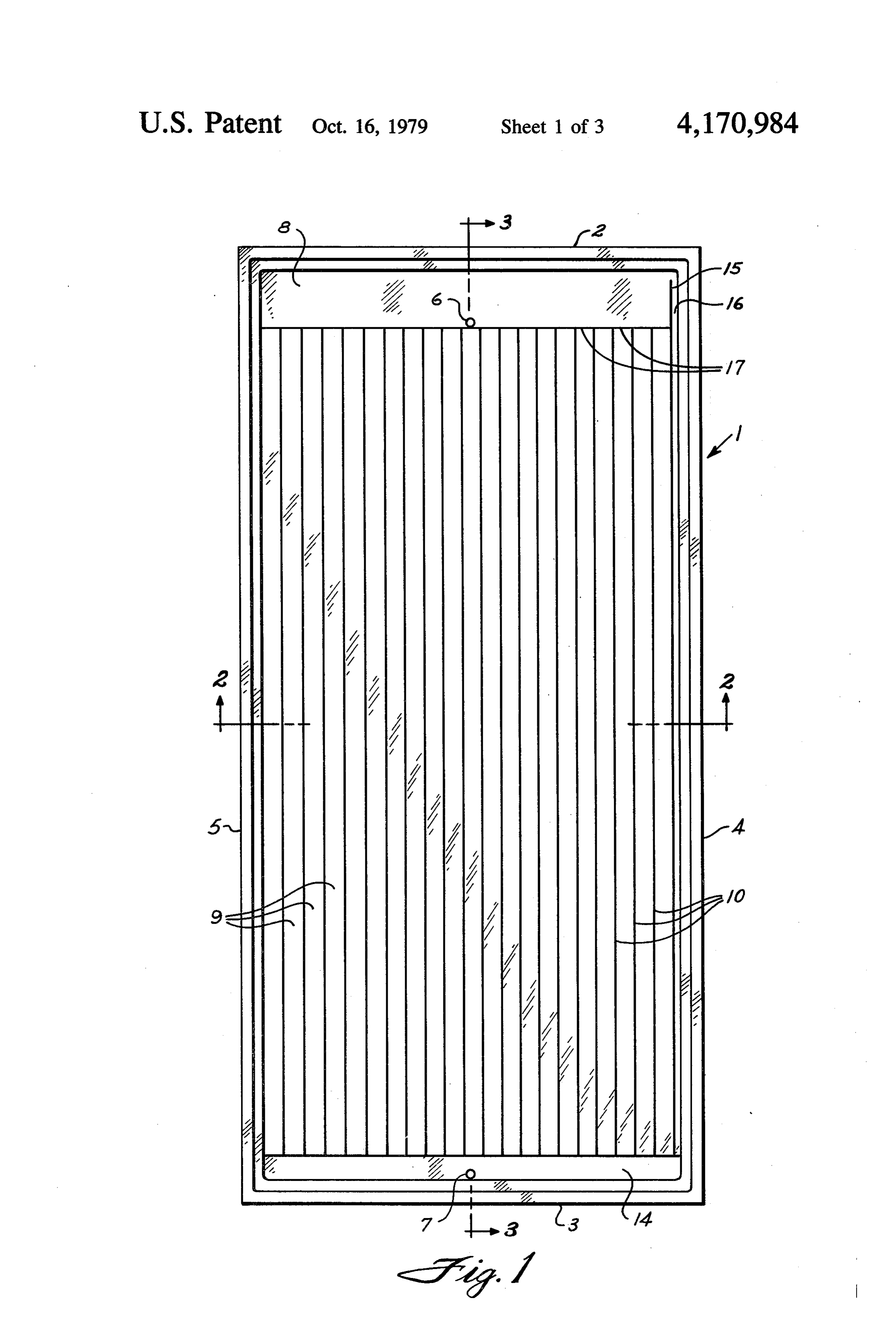
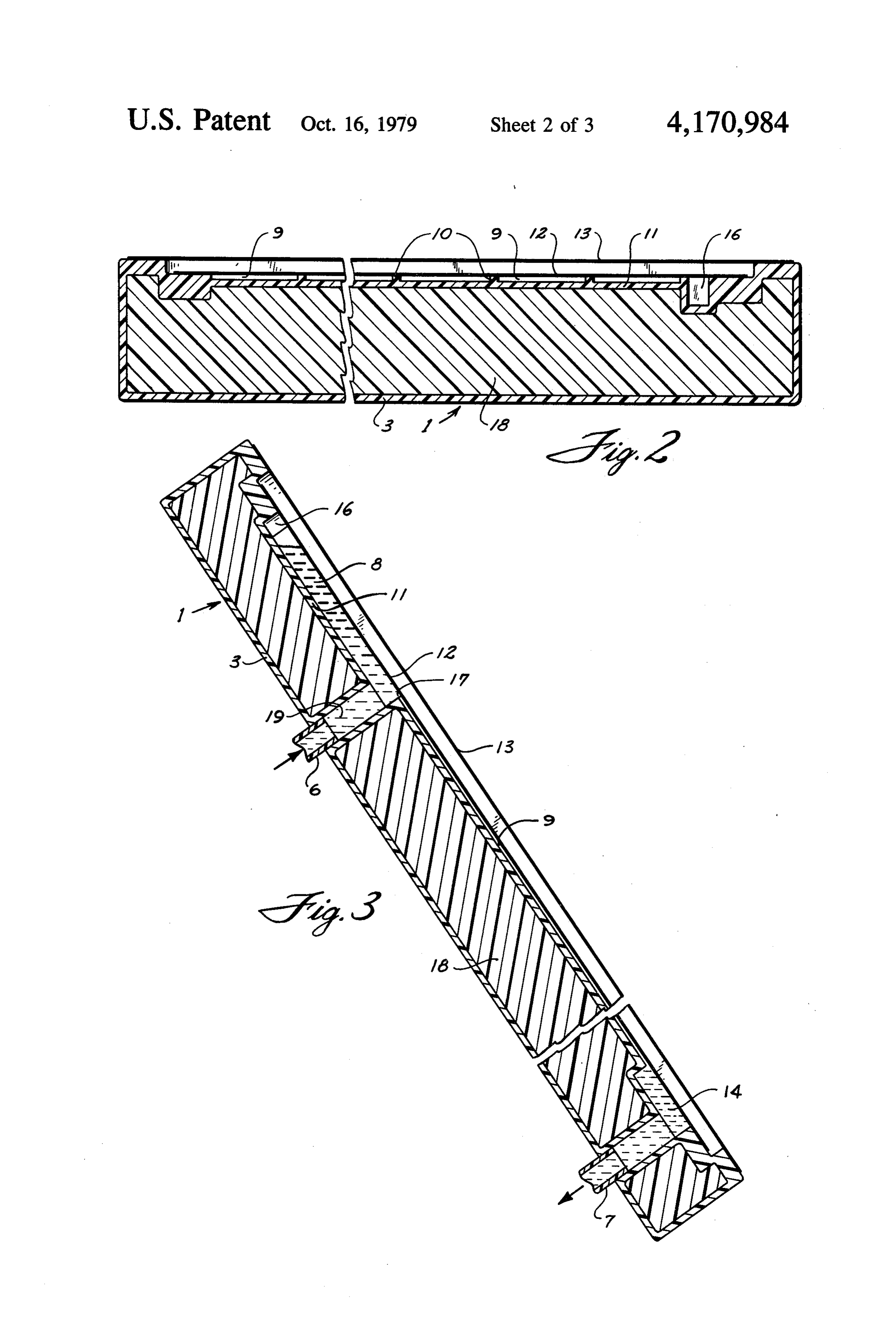
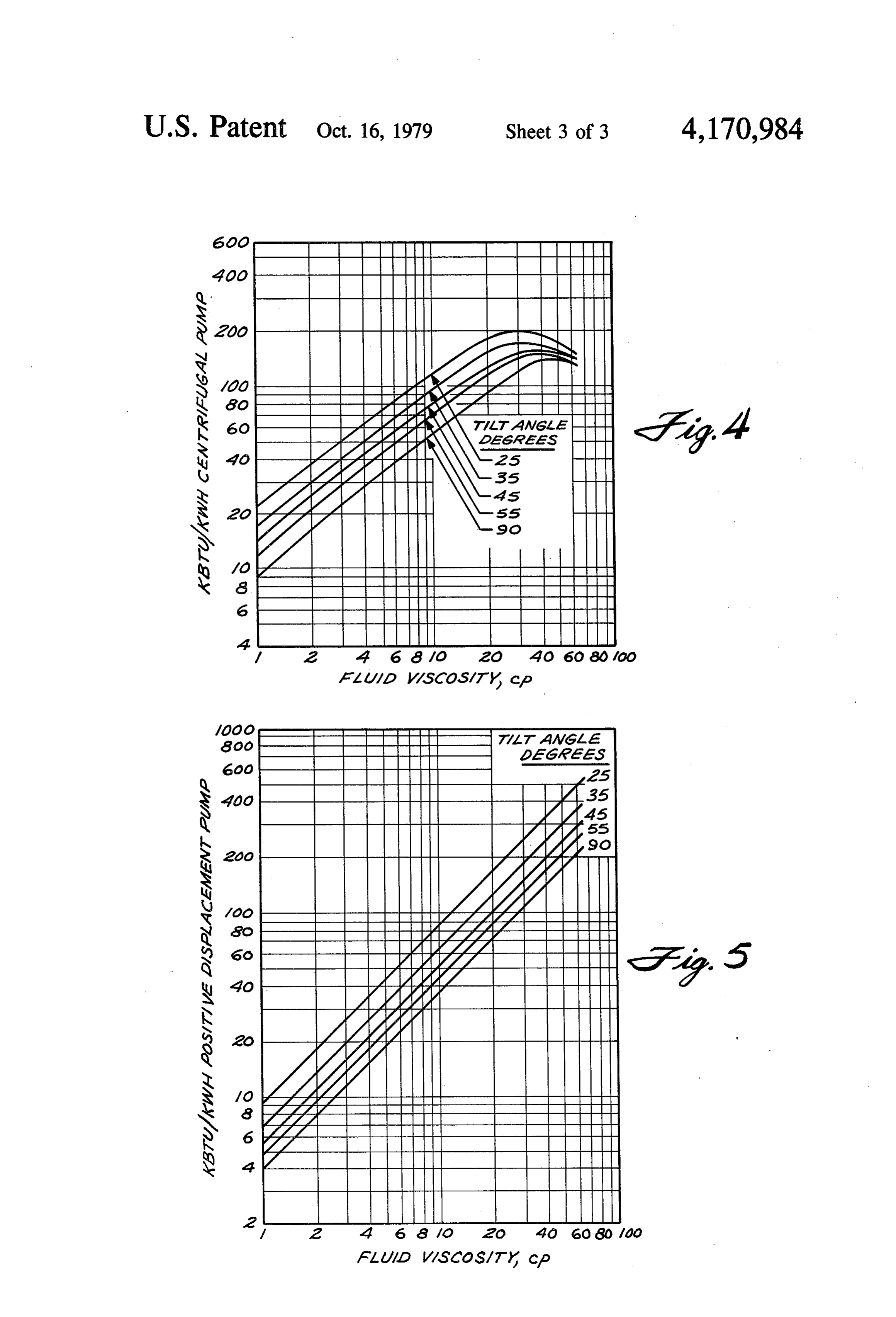
FIG. 1 is a top view of an embodiment of the solar by dividing by the fluid density or specific gravity of heat collector panel. the fluid (water) at operating temperature (120 F). FIG. 2 is a cross-section taken at 2-2 of FIG. 1. In the gravity-flow, flooded flow collector, the re FIG. 3 is a side elevation in longitudinal section taken quired viscosity (or the required rh) is calculated by at 3-3 of FIG. 1. 65 means of equation (2) which balances the gravitational FIG. 4 is a graph showing the calculated effect of force on the fluid with the force of fluid friction: viscosity on S/P ratio as a function of collector tilt angle, employing a centrifugal pump. p=wyp’g sin a/12th (2)
Page 7scan →
provide greater power cost savings. Initial cost savings where for both pump and motor are additionally obtained y=depth of fluid (0.05/12 ft) because of the smaller sizes needed, as can be seen from p=fluid density the Table. .
g=gravitational acceleration=4.17.108 ft/hr2 is .. 5 It can further be seen from Table I that AT per unit a=collector tilt angle length, for given operating parameters of the collector, rh=mass flow rate per panel increases with increasing viscosity of the fluid and that u= viscosity in lb/ft-hr by appropriate increases in viscosity, tilt angles up to 12=coefficient for frictional loss in stream-lined 90 can be employed.
flooded flow. 10 . In general, viscosity ranges of about 10 to 10,000 cp The equation for open flow is similar to that for can be employed to obtain the practical advantages of flooded flow except the coefficient for friction loss in the present invention. Preferably the range is about 20 stream-lined open flow is 3. to 1000 cp at 120 F.
Table I
Centrifugal
Collector Fluid Pump
Tilt Fluid Flow Exposure AT Pump Pump Motor S/P SvP Angle, Viscosity Rate, Time, panel, Size, Efficiency, Size, Centrifugal pos, dis. Deg. cp gpin sec/gpm F. BHP % KW KBTU/KWH KBTU/KWH
O 43 44 3.81. 0.74. 44 0.73 112 84.2
43 O 87 16.4 0.47 16 0.47 74 359
35 1 594 3.2 0.276 - 5.56 8. 4.88 16.8 6.84 10 59 32 2.78 0.89 50 0.88 ; 93.2 6.5
45 719 2.6 .228 6.72 81 S.89 13.9 5.66
43 17 2 9.63 0.54 24 0.53 SS 60
O 83 22 1.97 1.7 54 .16 70.7 43.2
32 26 72 6.30 OSS 36 0.55 149 138
66 13 148 2.6 0.65 s 0.64 128 276
O O2 18 1.61 142 S4 1.4 58.2 35.2
43 24 80 6.82 0.58 - 31 0.57 44 50
The increases in economy efficiencies provided by increased viscosities in terms of the ratio of total solar 8 'i 's energy absorbed vs. pump energy input is readily seen The advantage of dividing the sheet flow pattern into from the last two columns of the Table and in the a plurality of longitudinal channels has been discussed graphs of FIGS. 4 and 5. It will be noted that, in the 50 supra. The depth of the channel for flooded flow is not case of the centrifugal pump, the maximum S/P ratio, critical. It is influenced by such variables as viscosity, which corresponds to the system that collects the maxi- rate of flow, particular pump design, angle of tilt, and mum amount of solar energy per KW of pump power, the like. Optimum operating depths can be determined is, for the given condition parameters, achieved at a by routine calculation and experimentation. In general, viscosity of 32 cp at 120 F. for all tilt angles except 90° 55 the viscosity for maximum S/P increases with cube of where the optimum viscosity is 43 cp at 120". It should channel depth. - also be noted, however, that improved economy is ob- EXAMPLE tained at even higher viscosities, and that optimum w - - viscosities will change with different parameters, such A fluid of elevated viscosity was produced from the as fluid depth, operating temperature, etc. In the case 60 following components:
of the positive displacement pump, S/Pratio continues Water-99.08% to increase with increasing viscosities, with the maxi- Polyacrylamide 0.36% mum not reached until viscosity is greater than about I Carbon black-0.10% 1000 cp, where the pump, such as the Moyno pump, Surfactant (Tamol SN)-0.10% reacts to viscosity. From the point of view of initial costit 65. NaOH (stabilizer for C)-0.36% and maintenance, the centrifugal pump generally is The composition was diluted with sufficient water to most economical. However, the positive displacement produce two fluids having respective viscosities of 3 cp pump, though substantially higher in initial cost, can and 16 cp at 120 F.
Page 8scan →
A solar heat collector panel was built comprising five polyurethane, glass wool batt, and the like. The course longitudinal channels separated by thin plastic dividers of liquid 19 flow is shown in FIG. 3. and having dimensions: 1.84" widex0.023' deepX44' Although this invention has been described with long. The bottom (flow surface) and top (top fluid reference to illustrative embodiments thereof, it will be flooding surface) channel faces were made of ' thick apparent to those skilled in the art that the principles of plexiglass. A sheet of aluminum foil was positioned this invention can be embodied in other forms but between the lower sheet and the insulation to provide within the scope of the claims. reflectivity. The upper sheet rested on the top edges of I claim:
the channel dividers. The base of the panel was insu 1. In a gravity-flow, sheet-flow, solar-energy collec lated with 1" of polystyrene foam. A window made of O tor including a bottom fluid-flow surface lateral and end 6 mil acrylic film was positioned about 1" above the walls, a fluid inflow header, a fluid outflow chamber upper channel face. The enclosure was completed by and a first solid, substantially rigid transparent sheet or four sides of wooden plank with appropriate sealing. A window which extends across the entire fluid flow area header ' deepX6' longx12" wide was positioned at 15 of the collector at a spaced distance from the bottom the top across the top channel entrances. The header fluid-flow surface and is peripherally, sealingly attached was open at the bottom to provide a slit for feeding fluid to the lateral and end walls of the collector, the im into the channels. The panel faced south and was tilted provement wherein the fluid flowing in the collector is at an angle of 45, namely substantially perpendicular to a dark liquid having a predetermined viscosity which is the rays of the sun at solar noon. When fluid was fed by 20 at least about 10 Cp at 120 F.; said first transparent centrifugal pump into the header, the header filled to a solid sheet is at a predetermined distance from the bot level providing about a 3' static head at the channel surface and saidsurface;
tom fluid-flow the space between said bottom transparent first sheet is flooded with entrances. This small head appeared to be necessary to said fluid; and said fluid inflow header is provided with overcome the entrance pressure drop. Flow was uni overflow means to produce a desired head and to equal form down the flooded channels. Flooding flow rate for 25 ize pressure the 3 cp fluid was 0.150 gpm/sq. ft., corresponding to a predeterminedin said header and outflow chamber; said viscosity being sufficiently high, given flooding velocity of 3.8 in./sec. and an exposure time of other variable operating conditions of said collector, to 11 sec. in the 44' channels. The flooding flow rate for provide a desired temperature differential per unit the 16 cp fluid was 0.024 gpm/sq. ft. for a flooding length of said collector over a tilt angle range up to velocity of 0.63 in./sec. and a panel exposure time of 70 30 about 90.
sec. The S/P value for the 3 cp fluid was 34 and for the 2. The collector of claim 1 wherein the minimum 16 cp fluid 120. For the 3 cp, AT was 2.5 F. and for the viscosity is about 20 Cp at 120 F.
16 cp, AT was 17 F. Collector efficiency was calcu 3. The collector of claim 1 wherein the liquid is water lated to be 4% at 120 F. for both fluids. containing material which increases viscosity and im In FIG. 1, the solar heat collector panel 1 comprises 35 parts a dark color to the liquid.
a rectangular box with top and bottom side walls 2 and 4. The collector of claim 2 wherein the liquid is water 3, respectively, and lateral walls 4 and 5. Inlet and outlet containing material which increases viscosity and im tubes at top and bottom are 6 and 7, respectively. Inlet parts a dark color to the liquid.
tube 6 fills top header 8. The panel is divided longitudi 5. The collector of claim 1 wherein the dark color is nally into a plurality of longitudinal channels 9 by longi imparted by finely divided carbon or graphite. tudinal dividers 10 attached to bottom fluid flow surface 6. The collector of claim 2 wherein the dark color is 11, which is preferably of light color, e.g., white, or imparted by finely divided carbon or graphite. coated with a reflective metal, e.g., Al. Transparent 7. The collector of claim 3 wherein the dark color is sheet or window 12, preferably made of a transparent imparted by finely divided carbon or graphite. plastic such as plexiglass, is shown resting on the tops of 45 8. The collector of claim 4 wherein the dark color is channel dividers 10, thereby forming an upper channel imparted by finely divided carbon or graphite. 9 closure and permitting flooded flow if desired. As 9. The collector of claim 1 which has a plurality of shown in FIGS. 2 and 3, solid first transparent sheet or laterally spaced longitudinal channels separated each window 12 extends across the entire fluid flow area of from the other by longitudinal dividers which are sub the collector at a spaced distance from the bottom fluid 50 stantially perpendicular to the bottom fluid-flow sur flow surface 11 and is peripherally attached in sealing face.
relationship to the lateral and end walls of the panel, 10. The collector of claim 2 which has a plurality of thereby permitting said flooded flow in the volume laterally spaced longitudinal channels separated each between the upper surface of bottom surface 11 and the from the other by longitudinal dividers which are sub lower surface of window 12. The described arrange 55 stantially perpendicular to the bottom fluid-flow sur ment of said first transparent window 12 is convention face.
ally the case in sheet-flow, gravity-flow solar panels. 11. The collector of claim 3 which has a plurality of Transparent sheet or window 13, preferably made of a laterally spaced longitudinal channels separated each transparent plastic, is employed to retain the heat gener from the other by longitudinal dividers which are sub ated within the system. Lower chamber 14 receives the stantially perpendicular to the bottom fluid-flow sur fluid circulated in the channels and passes it out through face.
exit tube 7. Header 8 is provided with overflow baffle 12. The collector of claim 4 which has a plurality of 15 to provide an overflow channel 16 to limit the liquid laterally spaced longitudinal channels separated each in the header to a desired static head and to equalize from the other by longitudinal dividers which are sub pressure at the header and drain. Header 8 is provided 65 stantially perpendicular to the bottom fluid-flow sur at its bottom with a horizontal slit 17 opening across the face. .
top entrances of the channel. The base of the panel is 13. The collector of claim 5 which has a plurality of filled with insulation material 18, such as polystyrene, laterally spaced longitudinal channels separated each 9 from the other by longitudinal dividers which are sub . . 39. The collector of claim 15 wherein said overflow stantially perpendicular to the bottom fluid-flow sur means is a baffle. . . . . . . .
face. ‘. . . . . . . 40. The collector of claim 16 wherein said overflow 14. The collector of claim 6 has a plurality of laterally means, is a baffle. . spaced longitudinal channels separated each from the 41. The collector of claim 17 wherein said overflow other by longitudinal dividers which are substantially means is a baffle.
perpendicular to the bottom fluid-flow surface. 42. The collector of claim 18 wherein said overflow 15. The collector of claim 7 which has a plurality of means is a baffle.
laterally spaced longitudinal channels separated each * 43. The collector of claim 19 wherein said overflow from the other by longitudinal dividers which are sub 10 means is a baffle.
stantially perpendicular to the bottom fluid-flow sur 44. The collector of claim 20 wherein said overflow face. . . . . - means is a baffle.
16. The collector of claim 8 which has a plurality of 45. The collector of claim 21 wherein said overflow laterally spaced longitudinal channels separated each means is a baffle.
from the other by longitudinal dividers which are sub 15 46. The collector of claim 22 wherein said overflow stantially perpendicular to the botom fluid-flow surface. means is a baffle.
17. The collector of claim 9 wherein said transparent 47. The collector of claim 23 wherein said overflow sheet covers said channels in substantially abutting rela means is a baffle.
tionship to the upper ends of said dividers. 48. The collector of claim 24 wherein said overflow 18. The collector of claim 10 wherein said transparent 20 means is a baffle.
sheet covers said channels in substantially abutting rela 49. The collector of claim 1 wherein the fluid and the tionship to the upper ends of said dividers. fluid flow surfaces of said collector are mutually sub 19. The collector of claim 11 wherein said transparent stantially non-wettable.
sheet covers said channels in substantially abutting rela 50. The collector of claim 2 wherein the fluid and the tionship to the upper ends of said dividers. 25 fluid flow surfaces of said collector are mutually sub 20. The collector of claim 12 wherein said transparent stantially non-wettable.
sheet covers said channels in substantially abutting rela 51. The collector of claim 3 wherein the fluid and the tionship to the upper ends of said dividers. fluid flow surfaces of said collctor are mutually substan 21. The collector of claim 13 wherein said transparent tially non-wettable.
sheet covers said channels in substantially abutting rela 30 52. The collector of claim 4 wherein the fluid and the tionship to the upper ends of said dividers. fluid flow surfaces of said collector are mutually sub 22. The collector of claim 14 wherein said transparent stantially non-wettable.
sheet covers said channels in substantially abutting rela 53. The collector of claim 9 wherein the fluid and the tionship to the upper ends of said dividers. fluid flow surfaces of said collector are mutually sub 23. The collector of claim 15 wherein said transparent 35 stantially non-wettable.
sheet covers said channels in substantially abutting rela 54. The collector of claim 10 wherein the fluid and tionship to the upper ends of said dividers. the fluid flow surfaces of said collector are mutually 24. The collector of claim 16 wherein said transparent substantially non-wettable.
sheet covers said channels in substantially abutting rela 55. The collector of claim 11 wherein the fluid and tionship to the upper ends of said dividers. the fluid flow surfaces of said collector are mutually 25. The collector of claim 1 wherein said overflow substantially non-wettable.
means is a baffle. 56. The collector of claim 12 wherein the fluid and 26. The collector of claim 2 wherein said overflow the fluid flow surfaces of said collector are mutually means is a baffle. substantially non-wettable.
27. The collector of claim 3 wherein said overflow 45 57. The collector of claim 17 wherein the fluid and means is a baffle. the fluid flow surfaces of said collector are mutually 28. The collector of claim 4 wherein said overflow substantially non-wettable.
means is a baffle. 58. The collector of claim 18 wherein the fluid and 29. The collector of claim 5 wherein said overflow the fluid flow surfaces of said collector are mutually means is a baffle. 50 substantially non-wettable.
30. The collector of claim 6 wherein said overflow 59. The collector of claim 19 wherein the fluid and means is a baffle. the fluid flow surfaces of said collector are mutually 31. The collector of claim 7 wherein said overflow substantially non-wettable.
means is a baffle. 60. The collector of claim 20 wherein the fluid and 32. The collector of claim 8 wherein said overflow 55 the fluid flow surfaces of said collector are mutually means is a baffle. substantially non-wettable.
33. The collector of claim 9 wherein said overflow 61. The collector of claim 25 wherein the fluid and means is a baffle. the fluid flow surfaces of said collector are mutually 34. The collector of claim 10 wherein said overflow substantially non-wettable.
means is a baffle. 62. The collector of claim 26 wherein the fluid and 35. The collector of claim 11 wherein said overflow the fluid flow surfaces of said collector are mutually means is a baffle. substantially non-wettable.
36. The collector of claim 12 wherein said overflow 63. The collector of claim 27 wherein the fluid and means is a baffle. the fluid flow surfaces of said collector are mutually 37. The collector of claim 13 wherein said overflow 65 substantially non-wettable.
means is a baffle. 64. The collector of claim 28 wherein the fluid and 38. The collector of claim 14 wherein said overflow the fluid flow surfaces of said collector are mutually means is a baffle. substantially non-wettable.
Page 10scan →
65. The collector of claim 33 wherein the fluid flow surfaces of said collector substantially non-wettable.
66. The collector of claim 34 wherein the fluid flow surfaces of said collector substantially non-wettable. a 67. The collector of claim 35 wherein the fluid flow surfaces of said collector substantially non-wettable.
68. The collector of claim 36 wherein the fluid flow surfaces of said collector substantially non-wettable.
the fluid and 69. The collector of claim 41 wherein the fluid and are mutually the fluid flow surfaces of said collector are mutually * * substantially non-wettable.
the fluid and 70. The collector of claim 42 wherein the fluid and are mutually 5 substantially the fluid flow surfaces of said collector are mutually
71. The collector of claim 43 wherein the fluid and the fluid and the fluid flow surfaces of said collector are mutually are mutually substantially non-wettable.
10 72. The collector of claim 44 wherein the fluid and the fluid and the fluid flow surfaces of said collector are mutually are mutually substantially non-wettable.
Provenance
- Collection
- Patents citing this work
- Pages
- 10
- Method
- pdftotext (the PDF's own text layer) + pdftoppm 300dpi page scans
- Patent office record
- patents.google.com →
- Source
- Google Patents citing-documents table
- Assignee
- Atlantic Research Corporation
- Published
- 1979-10-16
- Transcribed from
- patentimages.storage.googleapis.com →