

patent · US3939819A
Solar radiant energy collector
24 February 1976
Text
Page 1bibliographic recordscan →
United States Patent (19)
Minardi
54 SOLAR RADIANT ENERGY COLLECTOR
(75) Inventor: John E. Minardi, Kettering, Ohio (73) Assignee: The University of Dayton, Dayton,
Ohio
U.S. Cl. ................................................ 126/271 (51 int. Cl’............................................. F24J 3/02 58 Field of Search..................................... 126/271
UNITED STATES PATENTS
1,747,826 2/1930 Gould................................. 126/271 1951,403 3/1934 Goddard............................. 126/27 | 2,460,482 2/1949 Abbot......... ... 126/271 2,566,327 4/1951 Hallock............................... 126/271
3,107,052 10/1963 Garrison ............................. 126/271 3,620,206 1 1/1971 Harris................................. 126/271 Primary Examiner-William E. Wayner
Attorney, Agent, or Firm-Cennamo Kremblas &
Foster
A solar energy collector having a transparent pane(s) with a flowing “black' liquid medium to absorb the solar energy directly. The specific apparatus com prises in a general embodiment a tubing of various planar configuration to provide a flat surface. Alterna tive embodiments include the free flow of a black liq uid over a flat surface. Other structure is described for heat retention and environmental control. The black liquids have a high rate of absorption to solar energy. 4 Claims, 12 Drawing Figures
Drawings
Page 2drawing sheetscan →
Page 3drawing sheetscan →
Page 4scan →
Still a further object and other features of the present
SOLAR RADIANT ENERGY COLLECTOR invention will become apparent from the following BACKGROUND detailed description when taken in conjunction with the drawings in which:
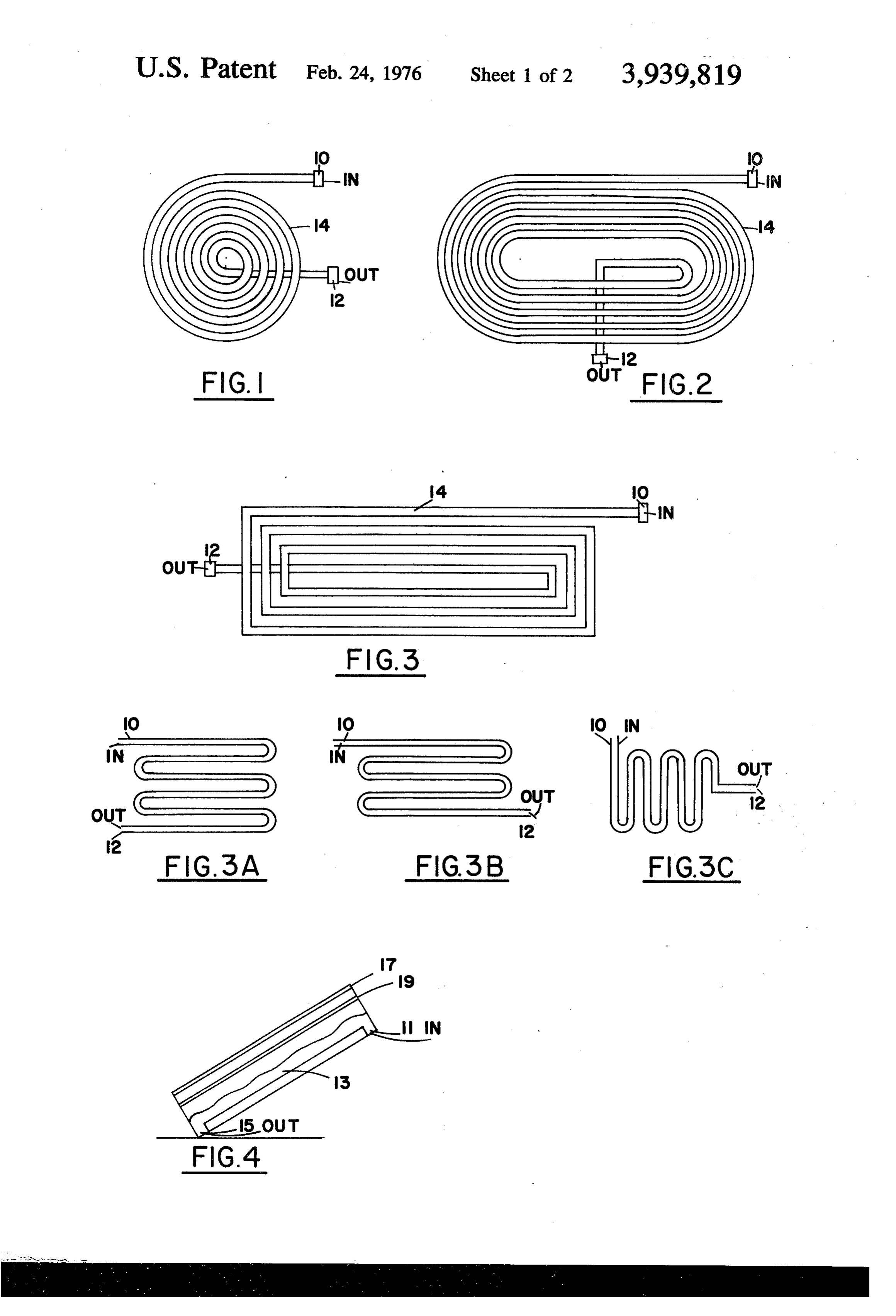
The prior art flat-plate solar energy collectors gener- 5 BRIEF DESCRIPTION OF DRAWINGS ally consist of a number of transparent panes and an absorbing surface, the surface in turn is of metal coated FIGS. 1 and 2 illustrate a first preferred embodiment with a suitable black absorbing material. A liquid or gas of the present invention where the tubes are wound in is passed either in front, behind, or around the absorb a circular and spiral planar surface. ing surface to extract energy from the absorbing sur 10 FIG. 3 is that structure of FIG. 1 wound to provide a face. The energy absorbed is then transported by the rectangular planar surface.
liquid or gas to the point of application. Suitable insula FIGS. 3A, 3B, and 3C is each represents that struc tion is placed behind the collector and along the edges ture of FIG. 1 wound to provide several alternative to reduce heat loss. Improvements have been made in zig-zag patterns.
the performance of flat-plate collectors by the use of 15 FIG. 4 is a cross sectional view of a constructed em selective black coatings which have a high rate of solar bodiment illustrating another alternative structure of absorption and low infrared emittance. Other improve liquid flow.
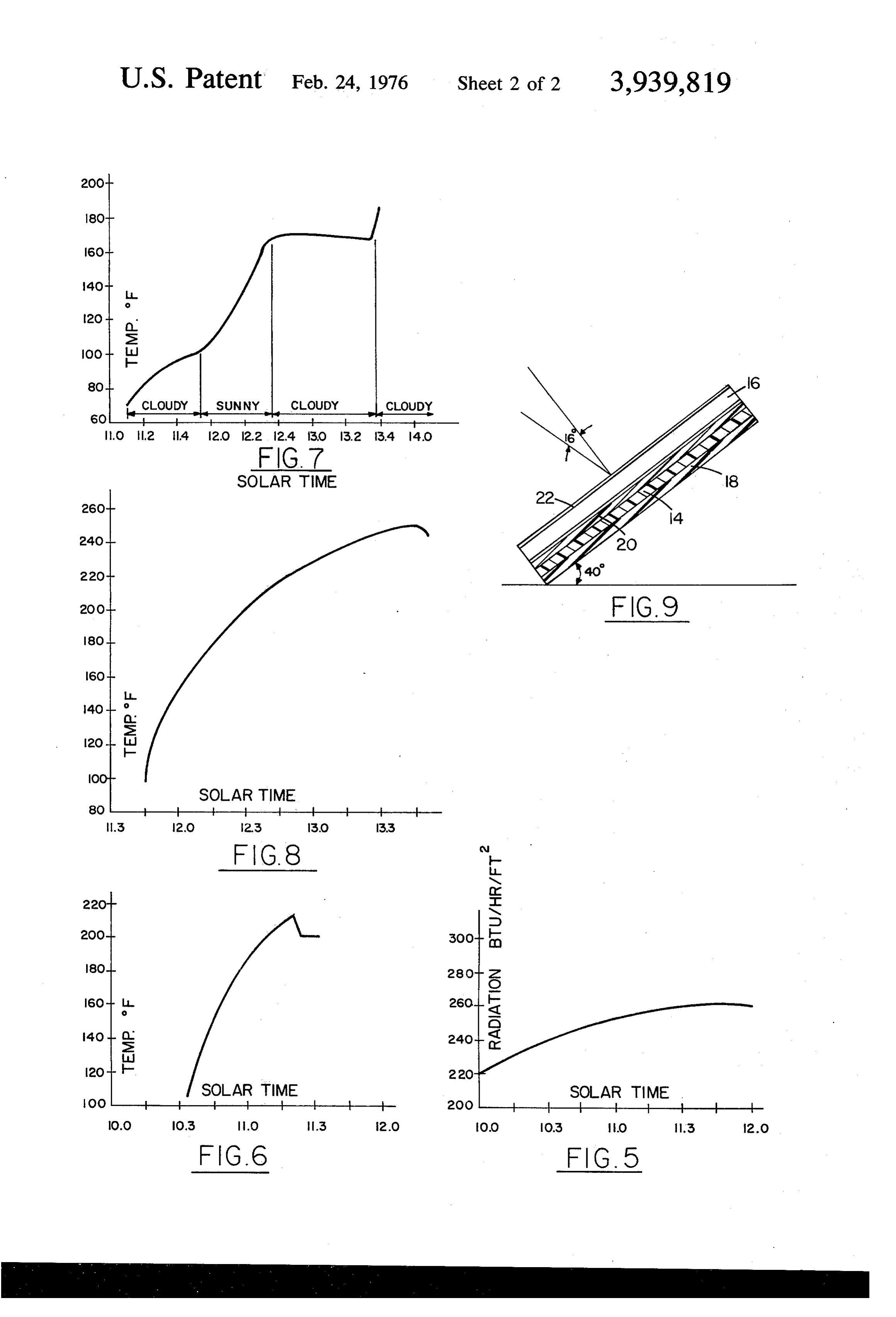
ments include evacuating the gas between the transpar FIGS. 5 and 6 are graphical illustrations of solar time ent panes and the absorbing surface. In some instances 20 versus calculated radiation and measured temperature a honeycomb structure is utilized to reduce conduction of the black liquid.
losses. FIGS. 7 and 8 are still other graphical illustrations of Other prior art solar energy absorption systems uti solar time versus temperature of the black liquid, and lize tubing - but the tubing is either metal or of clear FIG. 9 is a constructed embodiment of the entire plastic coated with a black absorbing material. In oper system of the invention.
ation these collectors have a nearly uniform tempera 25 DETAILED DESCRIPTION OF INVENTION ture over the entire surface; accordingly, being suscep tible to radiant heat losses. With particular reference to FIGS. 1 through 3 there is illustrated the basic structure of the invention. An
SUMMARY OF INVENTION elongated tubing 14 of transparent material is wound in 30 a manner for greatest solar exposure - but, yet, cover
The present invention comprises configurations wherein the solar radiation is directly absorbed. The ing a minimum overall flat sheet area. In FIG. 1 the metal absorbing surface and/or absorbing coating ma tubingin14FIG.3 is wound in a circular path, in FIG. 2. a curved terial are eliminated. In this way the solar energy is path, a rectangular path and in FIGS. 3A, 3B, directly absorbed in the heat transfer medium. The 35 is appreciated and and 3C in a back forth path.
principal advantage of this type of structure is that the a Itliquid that with each configuration there is input means 10 and liquid output means 12, heat losses are lessened since the heat transfer medium is the hottest material in the collector. Also the struc such as, couplings.
ture of the embodiments of the present invention pro since The tubing 14 is in a preferred embodiment plastic vide a gradual elevation of temperature as fluid moves 40 that can there are plastic tubings commercially available through the collector; only the outlet of the collector is that the tubingbe physically wound. The essential critereon is at the maximum temperature. With this structure the of radiant energybe absorption clean - that is, a minimum amount by the tubing perse.
radiant heat losses and edge losses are considerably Equally significant to the transparent tubing 14 is lessened.
The structure of the present invention generally con- 45 utilized in the invention is the energyiscollector; that the liquid passing therethrough black. The liquid prises in a first embodiment a clear-transparent tubing ingly, black is intended to include colloidal accord of a considerable length wound or folded into a planar sions, selective or nonselective black materials suspen surface. The liquid passing through the tubing is a black carbon black, a mixture of colloids, selective orsuch as nonse liquid - a liquid having a high rate of absorption to lective pure liquid compounds - of single or a mixture solar energy. 50
The preferred embodiment encompasses a closed ofIn-the components, or liquids with dyes or solutes. embodiment of the invention, the need for a structure to prevent heat losses from environmental metal absorbing surface along with its coating material conditions. An alternative embodiment has a sheet of black liquid passing over a reflecting or absorbing sur sorbed in the liquidthe is eliminated and heat solar radiation is directly ab transfer medium. In this way face in an enclosed structure. Data substantiates the 55 the heat losses are reduced since the liquid heat trans intended result of raising the temperature of the liquid fer medium is the hottest material in the collector. to a useful range - even under non-optimum condi In that the radiant energy collector is the liquid pass tions. ing through the tubing 14 it can be appreciated that the OBJECTS 60 liquid at the outlet 12 has the maximum exposure time. In this way there is a gradual elevation of temperature
It is accordingly a principal object of the present as fluid moves from the input 10 through the tubing 14 invention to provide a new and improved solar energy with the maximum temperature at the outlet 12. This is collector wherein the heat transfer intermediate is in contrast to the metal collectors which operate with a eliminated. more nearly uniform high temperature over their entire Another object of the present invention is to provide 65 surface. The lower surface temperatures reduce the a solar energy collector that is relatively simple in oper radiant heat losses from the black liquid collector. In ation and in actual construction and yet overcomes the addition, edge losses from the collectors would be prior art disadvantage of heat losses. lower as the entire outside edges of the configurations 5 in FIGS. 1 and 2 would be at the lower temperatures solar noon was estimated at 18. Due to cloudy sky and while at least one edge of collectors in FIGS. 3 and 4 very strong winds, the highest liquid temperature (no would be at the lower temperatures. flow) achieved in the collector was about 173F as With reference to FIG. 9 there is illustrated a con shown in FIG. 7. However, when flow was initiated in structed embodiment having an overall liquid collector the tubing 14 the liquid temperature was suddenly configuration similar to the schematic of FIG. 1. This increased to 190F. It was reasoned that the thermo embodiment comprised the clear plastic tubing 14 ap couple slipped relative to other components and failed proximately 25 turns. to record the liquid temperature in the coil. In this embodiment the tubing had an overall planar 10 In a fourth test the glycal ethylene liquid was mixed arrangement. In this way the tubing was wound but yet with the black liquid at 3 parts (vol) with 1 part (vol.) retained maximum exposure to solar radiant energy. of black liquid. This liquid has a boiling point of 260F The tubing 14 was enclosed in a box-like housing 16. at 800 feet above sea level. The black liquid was a The housing 16 in turn providing heat insulation to mixture 91 grams of Acheson's Aquadag paste to 1 liter prevent losses but yet permitting radiation to pass to 15 of distilled water. The calculated incident solar radia the tubing 14. The box-like housing 16 had as its base tion intensity at solar noon was 266 Btu/hr-ft. The a layer of foam insulation 18; the tubing 14 positioned angle of incidence at solar noon was estimated at 18. directly thereon. Placed immediately above the tubing The highest liquid temperature achieved in the col 14 is a sheet of clear plexiglas 20, thereafter an air lector (no flow) was 250°F, just about 10°F below the space and another sheet of clear plexiglas 22. boiling point of this liquid. The test was initiated at In the first test, of this embodiment, the black liquid 20 11:45 solar time. It is presumed had the test started comprised mixing 91 grams of Acheson's Aquadag earlier, the liquid would have reached its boiling point. paste (a dispersion of high purity colloidal graphite in Results of this test are illustrated in FIG. 8. water) with 1 liter distilled water. The fineness, purity Although FIG. 9 illustrates a preferred embodiment, and excellent suspension properties of the graphite 25 it is to be understood that modifications may be had particles enabled the diluted product to be employed in without departing from the spirit and scope of the in an extensive range of applications for which large parti vention, such as, the embodiment of FIG. 4. In this cle size dispersions and graphite powders are unsuit alternative embodiment the coil is eliminated. A liquid able. - flow 13 is entered at input 11 and permitted to flow in The overall structure was oriented 40° above the 30 a heat absorbing solar relationship before exiting at 15. horizontal facing magnetic South. The highest liquid In this embodiment all losses that may be attributed to temperature achieved in the collector (no flow) during the tubing are eliminated.
the first test was 185F at an ambient temperature OF It is of course understood once the liquid is heated its 78°F. The estimated direct solar radiation intensity was utilization as an energy source may be utilized. at solar noon calculated to be 283 Btu/hr.-ft. 35 What is claimed is:
The second test conducted included modifications on 1. A solar radiant energy collector comprising a the housing structure to provide more efficient insula source of liquid having a medium dispersed therein tion and heat retention to reduce heat losses. The high with a high absorptance to solar energy, a transparent est liquid temperature achieved in the collector (no tube of an extended length wound in a configuration to flow) was 210°F (the boiling point of this black liquid) 40 provide a flat-like planar surface for maximum expo at an ambient temperature of 36°F. With reference to sure to solar radiant energy, a reflector surface posi FIG. 5 the estimated incident solar radiation intensity tioned on the opposite side of said planar surface to at solar noon was calculated to be 271 Btu/hr-ft. The that exposed to said solar radiant energy a liquid inlet angle of incidence at solar noon was estimated at 16. and outlet joined with said transparent tube; and liquid This temperature was achieved in about 45 minutes 45 pressure means to cause said liquid to flow from said after the collector was exposed to the solar radiation at inlet through said tube and to said outlet. 10:30 solar time. 2. The solar radiant energy collector of claim 1 With this improved embodiment of FIG. 9 it was wherein said reflecting surface is a sheet-like surface in concluded that had the black liquid not vaporized, a a heat-loss type enclosure.
much higher temperature would have been achieved SO 3. The solar radiant energy collector of claim 1 with this collector. wherein said medium dispersed in said liquid is a colloi The next test included a glycal ethylene liquid mixed dal suspension.
with the black liquid at 3 parts with 1 part of black 4. The solar radiant energy collector of claim 1 liquid. This liquid had a boiling point of 260°F. The wherein said medium dispersed in said liquid is a car incident solar radiation intensity at solar noon was 55 bon black.
calculated at 266 Btu/hr-ft. The angle of incidence at k g : :
Provenance
- Collection
- Patents citing this work
- Pages
- 5
- Method
- pdftotext (the PDF's own text layer) + pdftoppm 300dpi page scans
- Patent office record
- patents.google.com →
- Source
- Google Patents citing-documents table
- Assignee
- The University Of Dayton
- Published
- 1976-02-24
- Transcribed from
- patentimages.storage.googleapis.com →