

patent · US4193389A
Solar radiant energy umbrella
18 March 1980
Text
Page 1scan →
United States Patent (19)
54 solar radiant energy umbrella
Woodside, N.Y. 11377
52 U.S. C. .................................... 126/451; 165/105;
742,961 1/1903 Boone .................................. 126/27 1,345,758 7/1920. Folsom..... ... 126/271 2,247,830 7/1941 Abbot ... so a son ... 126/27 2,760,920 8/1956 Olsen .................................... 126/270 2,994,318 8/1961 Lee ....... ... 26/270 3,643,648 2/1972 Tarcici ..... ... 26/270 4,010,614 3/1977 Arthur ..... ... 26/270 4,018,212 4/977 Hein et al..... ... 26/27 4,030,890 6/1977 Diggs ................................... 126/27
Foreign patent documents
512526 10/1920 France ..................................... 126/271 Primary Examiner-James C. Yeung
In a preferred embodiment, an umbrella has a reflective concave face serving a radiant energy collector when the umbrella is invertedly mounted, and a clamp clamps onto the umbrellas shaft a vessel containing water par tially filling the same, the vessel being of narrow thick ness and being supported at a point of converging re flected rays of energy, the vessel having upper steam space connected to a heating-vessel for heating typi cally a cup of coffee by heat-exchange with the coffee cup, and having a drain conduit for draining condensed steam back to the liquid-containing vessel, a steam con duit channeling steam through a liquid trap for remov ing water droplets carried by the steam, and the um brella when upright serving as typically a beach um brella which shifts with the wind by virtue of the shaft being off-set from the center.
8 Claims, 4 Drawing Figures
Drawings
Page 2drawing sheetscan →
Page 3scan →
and of containing equipement, and the like. Therefore,
SOLAR RADANT ENERGY UMBRELLA the controling though is to concentrate preferably light preferably by inexpensive reflection onto a very thin
THE SPECIFICATION layer of a small quantity of water preferably confined to 5 the area of focus of the concentrated light, with a small
This invention relates to solar radiant energy and a device and method of harnessing the energy, for use steam the collection space directing the steam speedily to matter to be heated. By the emphasis being placed when camping. on steam or vapor heat-energy, the heat-released is at an BACKGROUND TO THE INVENTION optimal maximum during the release of heat-energy at Prior to the present invention there has not been any condensation, as compared to minor caloric content quick and easy way of utilizing radiant solar energy for -and a low maximum possibility, when heating di rectly from-for example, mere hot water, or other constructive purposes of cooking and the like, devoid of vaporizable cumbersom equipement, adding to the problems of nor avaiability andliquid. Water because of normal ample non-toxicity is preferred to other liquids mally already too much baggage when going camping, hiking, to the beach or the like. 15 such as oils, or the like, much less alcohol or antifreeze or equivalent liquids.
SUMMARY OF THE INVENTION In understanding a major principle of the invention, Accordingly, objects of the present invention include an understanding of such being necessary to appreciate the obtaining of a multipurpose device and method of the inventive concept, further following comment will obtaining efficient harnessing of solar radiant energy. 20 be made. In a body of water were large in virtually Another object is to provide a novel beach umbrella infinite proportions, and in contrast, if merely a very having a second utility as a cooker or food warmer. small surface area of a surface of that body of water Another object is to obtain a beach umbrella which were subjected to normal sunlight rays in parallel as will withstand normally destructive winds, by virtue of 25 occur in normal sunlight, the heat-energy of absorbed shifting with the wind. sun light would be proportional first to the location on Another object is to obtain a novel steam-producing the earth's surface, as well as dependant upon whether vessel and combination thereof with an energy concen filtered by cloud cover or the like. Secondly, for what trator. Another object is to achieve foregoing objects at ever quantity of light energy does strike the predeter reduced economic costs. mined small surface area during a given period of time, Other objects become apparent from the preceding it may be said that the total energy is proportional to the and following disclosure. time of exposure; accordingly, if one waited long One and more of preceding objects are obtained by enough, a particular total quantity of any desired the preferred and other illustrated embodiments in tended to improve understanding of controlling princi 35 amount of energy could eventually be effected. How ever, from a practical point of view, such procedure ples, but not limiting the scope to solely the illustrated would not be of any value for heating or cooking pur embodiments, obvious variations and mechanical equiv poses unless there were a high-efficiency storage facility alents being also included. available such as a swimming pool insulated, or the like Broadly the invention may be described as a method as are utilized; in such event, the heat retained would be and a device for carrying-out the method, which insufficient for cooking much less for an inexpensive broadly includes the concentration of light rays onto a camping unit.
thin layer of vaporizable liquid contained within an heat by coolingThus, heat dissipation through loss of enclosure providing a small amount of steam or vapor or the like, normally dissipate heatstructures to environmental more and/or air quickly or as space thereabove, which vapor space is made to com quickly as the same is absorbed from the sunlight, under municate with matter such as food normally within a the situation described above. Next, with an unlimited vessel, to be heated or cooked. The controlling princi 45 body of water, the heat absorbed converted from the ple of the invention is the concept of concentrating the greatest possible radiant energy by the focusing or the radiantthe energy of the sun light rays, becomes diluted by heat-absorption of adjacent molecules of water of reflection of light rays to a common focus point on the face of or within a body of vaporizable liquid such as the large volume of adjacent water, such that, together water having a minimum of volume and thereby water 50 with with loss of heat from the entire body of water consid initially struck by concentrated radiant energy being ered exposure also the larger body to be heated by the small to sunlight rays, the overall temperature of the prevented from having the heat content thereof dissi pate into adjacent major quantities of cool water water would never reach a practically high temperature spaced-away from any point that rays might strike it; sufficient to be of any value for cooking, much less thereafter, the substantially instantly vaporized liquid is 55 within simple a brief period of time, and much less with a portable and inexpensive structure of device.
collected in minimal space to avoid storage heat dissipa tion to surrounding surfaces, and the matter to be ofThus, the present invention embodies the elimination the presence of water-body not having direct surface heated being either suspended within the steam space, exposure to the radiant energy sunlight rays, and also or alternately the steam being channeled in the shortest possible conduit with as much insulation as is reason- 60 the invention concentrates light rays preferably by re ably possible, to the point of direct heating or of heating flection to a common point, to increase the quantity of through a heat-exchange-wall such as the wall of a heat absorption per unit of time, while concurrently food-containing vessel; a further principle involved is avoiding the cooling of the heated water by virtue of the utilization of steam to heat the food, rather than cooling/heat-distribution among large quantities of ad having food sitting in a quantity of water or other va- 65 jacent water. In addition, there is the additional concept porizable liquid-it being a principle source of speedy that if the food (or vessel containing food) were in loss of heat energy by radiation and/or conduction mersed directly in the water being heated, firstly a when there is a major volume of liquid such as water, larger quantity of water would be required, and se 4 condly the temperature of the food or food-containing by exposure to steam, results in optimizing efficiency vessel could not rise above the "mean' (average) of the closer to theoretical possibilities. temperature of the water being heated (still cool, since Further to above-noted data, the BTU requirement to always there has to be some water to be heated at the heat one pound of water to produce steam therefrom radiant energy-exposure point) and any steam (if suffi for changing from water at 212 F. to steam at 212 F., cient heat were available to cause conversion to steam is 1000 BTU; however, note that in most instances it is after heat dissipation to the large quantity of water and not contemplated to heat a food material to produce the food (or vessel) absorbing heat) that might be pres steam therefrom; accordingly while greater amounts of ent. Accordingly, another feature of the present inven energy would be required initially to produce the steam tion is to make sure, as provided above, that ample 10 that will heat the food (or food vessel), and while for steam is produceable, followed by the thereafter sub every pound of steam-condensate 1000 BTU will have jecting the food (or food vessel) to exposure to solely been given-up, the actual needed BTU above-calculated (or at least primarily) the steam, and not the water from for heating the cup of coffee or water would not be of which the steam is produced. In further enhancement, a large magnitude necessary to boil-away the coffee or the steam is scrubbed of water droplets, whereby the 15 Water.
rapidly-produced steam is sufficient to heat or cook Actual efficiency of a concentration of light rays by food, such as eggs, bacon, coffee, or the like. As indi reflection on the shinny inner surface of a hemisphere of cated in the Figures, or otherwise, the scrubbed water an inverted beach-umbrella of the present invention, is and/or steam condensate may be recycled, in order to about 99%; BTU production is at about 80% efficiency, benefit from residual heat content thereof, maximizing 20 or 160 BTU at 8:30 AM on 8/5/77; heat dissipation is efficiency. Also, it is to be recognized that while the about 5% of this amount, leaving about 152 present invention is primarily directed to a portable BTU/Hr/Sq.ft., which for a 6 ft. diameter would pro camping or picnicing unit, the above-described princi duce 4297 BTU/Hr. or 71.6 BTU per minute, whereby ple and structure of the invention may be employed on a cup of water (half-pound) would be heated in about a larger scale to other heating and/or cooking or ener 25 one minute, from 60' F. to 212 F. (excluding any gy-units. amount of heat needed to convert the water being radi Another advantage to the circular umbrella arrange ated from the 2.2-water to the 212-steam). Actual ment for the present concept, is the benefit of availabil experience has demonstrated about three minutes time ity to concentrate rays of radiant energy as sunlight, required, utilizing a constructed device of this inven from all points around 360 degrees onto a small local 30 tion.
ized surface area, permitting both concentration of heat It is to be recognized that much speedier results are thereby as well as avoiding heat dissipation over a large obtainable during summer than winter, and nearer the area, as well as the water in the small area being held to equator.
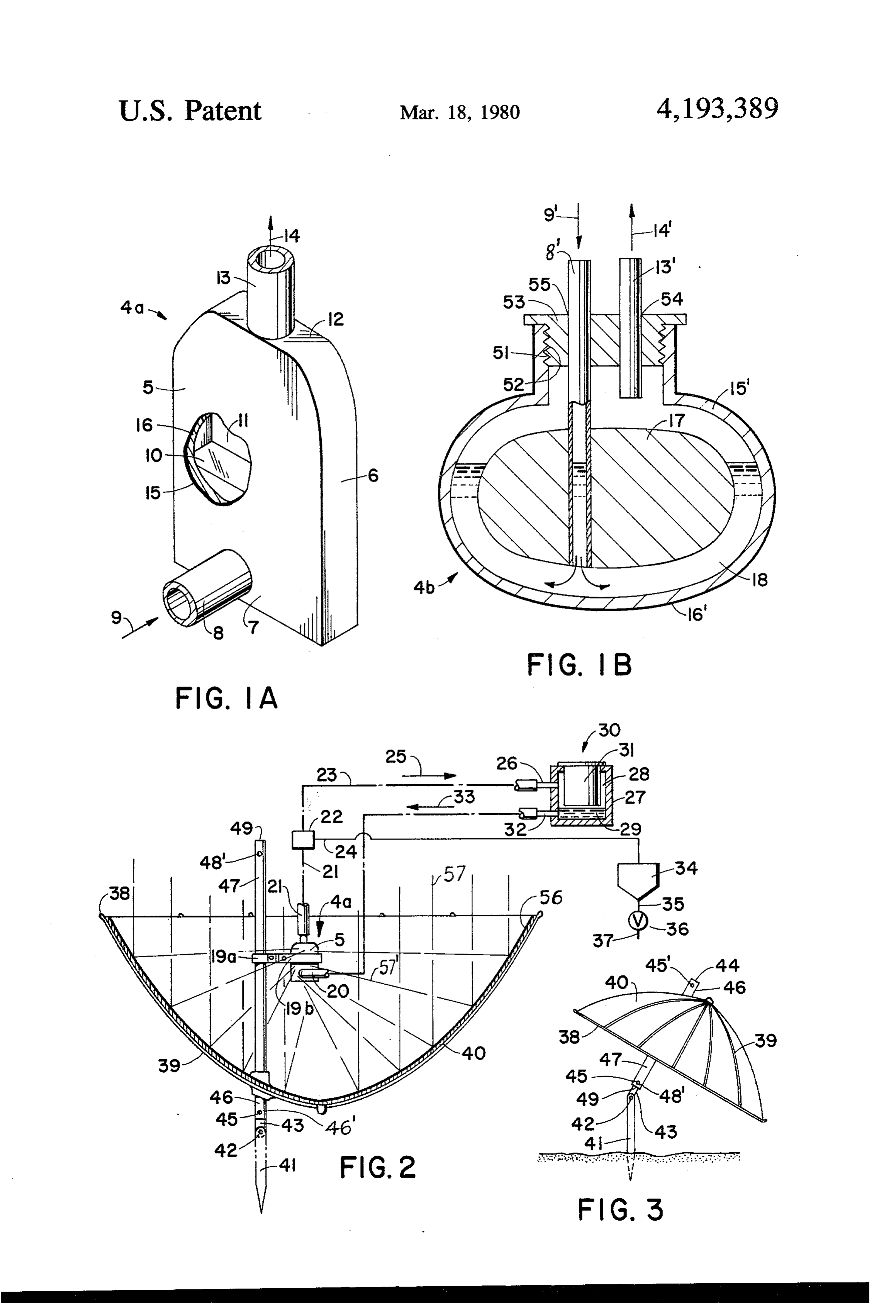
a low(small) volume thereby also. The invention may be better understood by making Theoretical maximum heat energy from the sun shine 35 reference to the following Figures.
on the earth's surface, a solar constant, is 1340 watts per THE FIGURES square meter, or 1.92 calories per square centimeter per minute, or 424.7 BTU per hour per square foot. FIG. 1A illustrates a perspective side view with par The actual solar heat energy in New York City on tial cut-away for improved illustration, liquid-containa Aug. 9, 1977 at 7:30 AM was 150 BTU per hour per ble boiler vessel, and inlet and outlet conduits thereof square foot, and at 8:30AM on Aug. 5 was at about 200 for channeling-in condensate of steam and for channel BTU per hour per square foot, and at noon on Aug. 5 ing-out steam from the steam-space of the vessel. was between 250-300 BTU per hour per square foot; all FIG. 1B illustrates in side cross-sectional view, an of this data was measured by a Solar Meter Model 776 alternate embodiment of liquid-containable boiler ves Dodge Products, Houston, Texas. 45 sel, and inlet and outlet conduits thereof. The area of a 3 foot diameter circle provides 7.0686 FIG. 2 illustrates a side partial cross-sectional view of Sq. ft.; this area at 8:30 AM/New York City can typi solar radient energy umbrella cooking device symboli cally collect therefore about 1413.72 BTU per hour per cally illustrating the both structure and mechanism of foot, or 23.56 BTU per minute per 3 ft diameter. operation, diagrammatically, with the umbrella in an To heat a pound (two cups) of water from 60' F. to 50 inverted state.
212 F. requires 152 BTU. Accordingly, for a 3 foot FIG. 3 illustrates another view in side view of the diameter area at 23.56 BTU per minute, 6.6 minutes umbrella of the FIG. 2 embodiment, except in this view would be required. the umbrella portion being utilized solely as a shade For a larger area as would be provided typically by a producing umbrella in the upright position. beach umbrella of 6 foot diameter, the total area is about 55 28 square feet, and 8:30 AM New York (8/7/77) would DETAILED DESCRIPTION OF THE give 5,600 BTU/Hr. or 93.0 BTU per minute, whereby NVENTION a cup of water (or coffee) would boil (reach boiling Most broadly the invention defined, the invention temperature) requiring of 152 BTU from an initial above-described may be considered to be a method temperature of 60, within about one minute assuming which includes the causing of radient energy to be con 100% efficiency, which of course is not possible, but centrated onto a focus point (area) localized where serves as a guide and goal in any event. there exists a thin layer of vaporizable liquid such as By the present invention, the concentration of this water held within a small volume of space providing a heat to a centralized small surface area and the utiliza minor and minimum amount of effective steam-collec tion of maximum exposure of all water-volume mole 65 tion space, and contacting the steam produced by va cules to radiant energy rays, and minimal dilution of porization of the water, with a material such as food or heat energy by non-exposed water molecules by hold a food-containable vessel either within the steam space ing non-exposed molecules to a minimum, and heating or to which the steam is channelled. The thin layer of 5 water (or comparable liquid) is sufficiently small as to is. With regard to FIG. 2, clamps 19a and 19b support readily vaporize as a result of concentrated heatenergy s the liquid-containable vessel 4a on the shaft 47, the absorbed thereby. The steam space above the water (or conduit. being continuous with the FIG. 1A inlet other liquid) surface is sufficiently small as to effect a conduit l, and conduit 21 being continuous with the miximal contact of vapor (steam) therein with the mat steam travels outlet 13, to liquid trap 22 from which steam through conduit 23 in direction 25 into heater ter to be heated, rather than having a large steam reser -vessel inlet 26 into heater vessel 27 having steam-space voir serving no good purpose and from which enlarged 28 and condensate 29, with the food vessel 30 having a outer peripheral surfaces of the volume (space) thereof lip that thereby suspends would be subject to a higher total amount of heat dissi 10 tainer-portion 31, the foodthevesselfood vessel with the con 30 being typically a
As noted-above, further embodiments of the inven 'cup. Condensate 29 leaves by outlet structure 32 in tion include the combination of elements for practicing direction lected 33 in conduit 20. The conduit 24 drains col water from the conventional liquid trap 22, car the method, as well as including a multi-use beach um rying the same brella having also special utility of shifting with the 5 drained by valveto36vessel 34, periodically or otherwise in line 35 into line 37. The conduit wind, thereby avoiding likelihood of wind-damage to 24 may alternately drain directly into line 20 if desired.
Conventional technology
More particularly, with reference to the various Fig pressures, allowing the water is employed to prevent back ures, for common elements of the same embodiments ;34. to freely drain into vessel the same indicia are utilized, and for corresponding 20 The solar collection of energy typically works by the elements of different embodiments, "prime' indicia are sun lights rays as diagrammatically illustrated, striking utilized for corresponding elements. FIGS. 1A and 2 the innershiny coating 56 as rays 57 in parallel from the represent a common embodiment, for the steam-pro sun and reflected rays 57" onto face 5, for example. The ducing boiler vessel of FIG. 1A; likewise, the FIG. 3 umbrella 40, has reinforcing ribs 39 and supporting . illustrates a common umbrella in an upright-usage state, 25 outer ring 38, these being of any conventional material as compared to the same umbrella in an inverted-usage such as plastic or metal. Stake 41 has hinge-pin 42 con state of harnessing solar energy as a part of the greater necting mounting shaft 43 which includes depressible combination. conventional button 45 which when extended locks into In FIG. 1A, liquid-containable vessel 4a is a steam the tube-portion 46 in aperture 46 thereof, and into tube producing boiler vessel having opposite parallel faces 5 30 portion 49 of shaft 47 by aperture 48" as shown in the defining therebetween thin space 11 which in operation FIG. 3 illustration. The hinged shaft 43 is wedge-fitted has upper steam free-space and in the lower portion such that position is normally held fixedly unless manu thereof water 10, the thin space corresponding to nar ally manipulated to a new desired position. Pin 42 may row-width wall faces 6, resulting in a maximum expo also be of the type that may be tightened and loosened sure of water 10 to heated wall-thickness 15 of the sur 35 alternately.
rounding vessel structure, with a minimum of volume -It is within the scope of the invention to make varia space-away from contact with surrounding wall struc tions and substitution of equivalents within the ordinary ture. At a lower portion 7 of the vessel, there is located skill of an artisan in this field of art. a steam-condensate return inlet-conduit 8 for conden I claim:
sate traveling inwardly in direction 9, and at upper 1. A device for harnessing radiant solar energy com portion 12 there is the steam outlet conduit 13 for steam prising in combination: an elongated supporting struc traveling outwardly in the direction 14. Illustrative ture, a concave reflective surface adapted to receive a cut-away makes possible the showing of thickness and plurality of rays of radiant energy such that reflected existence of darkened (preferably black) heat-absorbing rays converge to a substantially common point substan layer 16 as an outer-coating, preventing also reflection. 45 tially coincident with space associated with the concave As well as having corresponding elements, the FIG. reflective surface, said elongated supporting structure 1B embodiment typically represent a spherical embodi including a first end extending from said reflective sur ment-vessel 4b having a central preferably metallic face in juxtaposition to and spaced-from said common block 17 occupying substantially all central interior point, and an opposite remaining end of said elongated space whereby the water layer 18 is thin thereby pro 50 supporting structure extending from an opposite face of viding that most water volume has the water molecules the concave reflective surface and adapted for support thereof in close proximity to vessel wall structure re ing the concave reflective surface in a predetermined ceiving the radiant energy rays. energy ray-receiving position; clamping means for It should be understood that it is contemplated that clamping a liquid-containable vessel onto said first end the boiler vessel walls may be transparent, but such is 55 of said elongated supporting structure, adapted such not preferred because normally there would be a that a liquid-containable vessel supported by said greater reflection loss of radiant energy. clamping means is positioned substantially at said com In the FIG. 1B embodiment, a further benefit of the mon point; and as the liquid-containable vessel, a liquid central metallic block 17 is that as heat is absorbed by containable vessel of predetermined shape at said com that block, it becomes a heater, heating water molecules mon point, the predetermined shape being character coming in contact therewith; normally, however, such ized to maintain liquid adjacent inner wall surfaces of would be considered a "constant', once initially quickly the liquid-containable vessel and within a thickness heated. range below a predetermined maximum layer-thickness Also in the FIG. 1B embodiment, there is a neck such that liquid volume does not exceed volume re portion having inner female threads 52 for receiving the 65 quired for absorbing all energy transmitted through said male threads 51 of plug 53 which has apertures 54 and inner wall surfaces; and a vaporizable liquid within the 55 for the outlet and inlet conduits 13' and 8' respec liquid-containable vessel in an amount of said thickness range below said predetermined maximum layer-thick tively.
Page 6scan →
ness of a volume sufficient to absorb substantially all determined maximum layer-thickness of liquid adjacent heat energy transmitted through said adjacent inner inner wall surfaces of the liquid-containable vessel; wall surfaces, whereby excessive energy dilution is maintaining a predetermined amount of liquid within avoided and heat energy is obtainable in high concen said liquid-containable vessel in an amount sufficient to tration within the thickness range, said amount being absorb substantially all heat energy transmitted through insufficient to fill a predetermined minimum of substan said adjacent inner wall surfaces and up to said prede tially enclosed space above liquid level of said liquid termined maximum layer-thickness sufficient to avoid sufficiently to provide for collection of vapor vaporized excessive energy dilution and to obtain concentration of by heat within said liquid, and vapor channeling means heatenergy within said predetermined maximum layer for channeling vapor from said enclosed space to a O thickness of liquid, and concurrently maintaining a pre heating vessel into enclosure space thereof, and as said determined minimum substantially enclosed space heating vessel, a liquid-containable heating vessel con above liquid-level sufficient for collection of vapor nected to receive vapor by said vapor channeling vaporized by heat within said liquid; and channeling means, said vapor channeling means including a liquid liquid-carrying vapor from said enclosed space to a trapping means for trapping liquid physically carried by 15 heating vessel into enclosure space thereof and trapping vapor from the enclosed space passing through said liquid physically-carried by said liquid-carrying vapor vapor channeling means. during said channeling.
2. A device of claim 1, in which each of opposite ends 5. A method of claim 4, including draining condensed of said elongated supporting structure is adapted for liquid from the enclosure space of the heating vessel, alternately supporting the concave reflective surface at 20 into a lower portion of liquid-containable space of the variable angles, alternately as a ray collector and as a liquid-containable vessel.
shade-providing umbrella. 6. A method of claim 5, including heating matter 3. A device of claim 1, including liquid return means removably placed within the enclosure space in heat for channeling condensed liquid from said liquid-con transfer relationship with hot vapor within the enclo tainable heating vessel into a lower inner space of said 25 sure space, and thereafter removing the matter in a heating vessel. heated state.
4. A method for harnessing radiant solar energy, 7. A method of claim 6, including placing the matter comprising in combination: arranging a concave reflec into a container before said heating, and placing the tive surface to receive a plurality of rays of radiant container with the matter-contents thereof within the energy such that reflected rays converge to a substan 30 enclosure space.
tially common point substantially coincident with space 8. A method of claim 4, including placing food matter associated with the concave reflective surface; position into said enclosure space in heat-transfer relationship ing a liquid-containable vessel of predetermined shape with hot vapor within the enclosure space, and utilizing at said common point, the predetermined shape being water as said liquid.
characterized to maintain liquid thickness below a pre 35 k
Provenance
- Collection
- Patents citing this work
- Pages
- 6
- Method
- pdftotext (the PDF's own text layer) + pdftoppm 300dpi page scans
- Patent office record
- patents.google.com →
- Source
- Google Patents citing-documents table
- Assignee
- Ku Paul H Y
- Published
- 1980-03-18
- Transcribed from
- patentimages.storage.googleapis.com →