

patent · US4262659A
Solar radiation absorbing panel
21 April 1981
Text
Page 1bibliographic recordscan →
United States Patent (19)
Brzezinski
54 SOLAR RADIATION ABSORBING PANEL
(75) Inventor: Joseph Brzezinski, Franklin, Ohio 73 Assignee: Valley Industries, Inc., Cincinnati,
Ohio
51 Int. Cl. ........ a 8 a 8 × 8 a 8 w w w w we so w w F24J 3/02 52 U.S. Cl. ......................... ... . . . . . . . . . 126/449; 126/445;
2,480,706 8/1949 Brinen .................................. 126/446 3,265,127 8/1966 Nickol et al. ........................ 165/152 3,611,534 10/1971 Keith .............. 29/57.3 V 3,863,621 2/1975 Schoenfelder ....................... 126/449 3,905,850 9/1975 Darm ................................... 165/166 4,002,200 1/1977 Raskin ... ... 165/170 4,016,861 4/1977 Taylor. ... 165/166 4,019,494 4/1977 Safdari....... ... 126/449 4,078,548 3/1978 Kapany ................................ 126/449
4,090,494 5/1978 Borst .................................... 26/450 4,154,222 5/1979 Yu ........................................ 126/449 Primary Examiner-Daniel J. O'Connor
Attorney, Agent, or Firm-Frost & Jacobs
A solar radiation absorbing panel including a flat base sheet of solar radiation absorptive material having a plurality of spaced sinuously shaped series of individual rectangular tab members extending away from the upper surface of the base sheet. Each of the tab mem bers is formed by severing the sheet along a continuous line leaving a portion of the base sheet attached between the ends of the severed lines, and bending the tab mem ber along the attached portion away from the surface of the panel, leaving an opening in the base sheet such that the spaces between the tab members form fluid passage ways for directing fluid from the panel inlet to the panel outlet. The panel may also be provided with support sheet underlying the base sheet to block the openings to prevent fluid flow therethrough. The panel may be fabricated in a single stamping and bending operation, thereby eliminating separate fabrication steps associated with conventional solar radiation absorbing panels.
34 Claims, 9 Drawing Figures
Drawings
Page 2drawing sheetscan →
Page 3drawing sheetscan →
Page 4drawing sheetscan →
Page 5drawing sheetscan →
Page 6scan →
surface of the panel to increase the collecting efficiency
SOLAR RADATION ABSORBNG PANEL of the solar collector and for forming air passageways for directing fluid from the inlet to the outlet. The re
SUMMARY OF THE INVENTION sulting panel is constructed in such a manner as to elimi There are numerous concepts for the collection of 5 nate the separate fabrication step of attaching the fins to solar radiation. These concepts range from the most the underlying plate inherent in prior art solar radiation simple-a window-to those that are quite complex and absorbing panels. In a preferred embodiment, the panel require advanced technology for their development, comprises a substantially flat plate-like rectangular such as solar cells, for instance. sheet of solar radiation absorptive material, which may Of the many heat collection concepts presently being 10 be provided with additional solar radiation absorption developed, the relatively simple flat-plate collector has enhancing coatings, bounded by spaced side and end found the widest application. Its low fabrication, instal edges, the end edges forming the fluid inlet and outlet, lation and maintenance cost, as compared to higher respectively, of the panel.
temperature heat collection shapes, has been the pri 15 Means project upwardly from the upper surface of mary reason for its widespread use. Additionally, flat the panel for forming a plurality of parallel sinuous air plate collectors can be easily incorporated into a build passageways for directing the working fluid from the ing shape, provided the tilt and orientation are properly inlet to the outlet. In a preferred embodiment, these calculated. means are formed by a plurality of individually formed As is well known in the art, a flat-plate collector tab members extending upwardly from the upper sur generally consists of a solar radiation absorbing plate or 20 face of the panel. Each rectangular-shaped tab member panel, often metallic, which may be flat, corrugated or is formed by making a C-shaped cut in the panel, leav grooved. The plate may be painted black, or provided ing one edge of the tab member attached to the panel. with other absorptivity increasing coatings, to increase The tab member is then bent upwardly to a vertical absorption of the sun's heat. In general, such collectors position such that the tab member is directed generally are covered with a solar radiation transmissive cover 25 sheet to trap heat within the collector and reduce con from the inlet edge of the panel toward one of the side vective cooling of the absorber. The captured solar heat edges at a 45° angle with respect to the inlet edge. A second tab member is formed in a similar manner is removed from the absorber by means of a working fluid, generally air or water, which is heated as it passes such that the adjacent edges of the first and second tab through or near the radiation absorbing plate. The members are 30 members substantially perpendicular. Additional tab are similarly formed to create a zig-zag heated working fluid is then transported to points of use shaped series of tab members extending generally be or to storage depending on energy demand.
It has been found that the collection efficiency of tween the inlet and outlet of the panel. such solar collectors can be significantly improved by A similar series of tab members is formed in staggered providing the radiation absorbing panel or plate with a 35 spaced parallel relationship with the first set of tab plurality of continuous upstanding fins arranged in members to form a zig-zag-shape or sinuous air passage spaced relationship so as to form fluid passageways way extending between the inlet and outlet of the panel. extending between the solar panel inlet and outlet. Gen Additional parallel air passageways may be formed in a erally, the continuous fins are positioned normal to the similar manner, as required, by merely forming addi absorbing plate such that solar rays reflected from a tional series of adjacent tab members. particular absorptive surface area on the fins or the A substantially flat rectangular plate-like sheet of absorbing plate will be absorbed by other surface areas, solar radiation absorptive material may be positioned thereby preventing reflection of the solar radiation beneath the panel containing the upstanding tab mem through the solar radiation transmissive cover. Further bers to block or cover the rectangular-shaped openings more, the fins tend to act as turbulators increasing tur 45 formed by the upstanding tab members. The entire unit bulance of the fluid and thereby increasing the effec may be positioned within a box-like enclosure and cov tiveness of heat transfer from the panel surfaces to the ered with a solar radiation transmissive sheet to form working fluid. A novel arrangement for such continu the completed solar collector, as it is well understood in ous fins is illustrated in my co-pending application Ser. the art. : No. 06/031,227, filed Apr. 18, 1979 and entitled Solar 50 It will be observed that this method of manufacture Heat Collecting Unit For Forced Air Systems. In the eliminates the separate fabrication steps required by preferred embodiment described therein, the upstand conventional solar radiation absorbing panels where ing sinuous parallel spaced fins are provided with a individual sinuously-snaped continuous fins must be number of tabs projecting downwardly at spaced loca individually attached by welding, soldering or other tions from the lower edge of the fins, which cooperate 55 means to the underlying base sheet. In the present in with similarly spaced slots in the absorptive plate to vention, the upstanding tab members may be rapidly provide means for attaching the fins to the plate. In and easily formed by a single stamping and bending other embodiments, the fins are resistance welded to the operation, or by consecutive stamping and bending supporting absorptive plate. In either event, these meth operations.
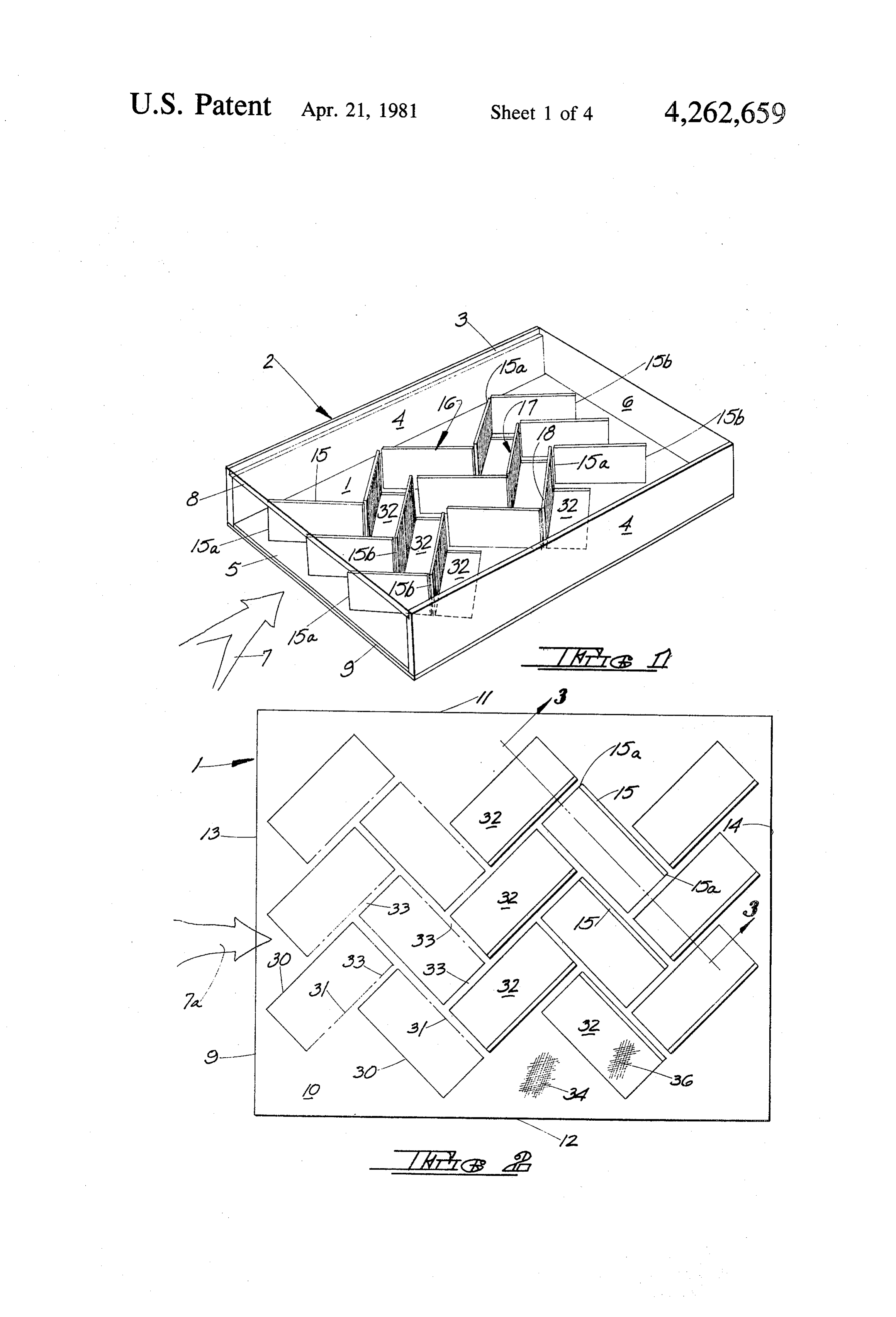
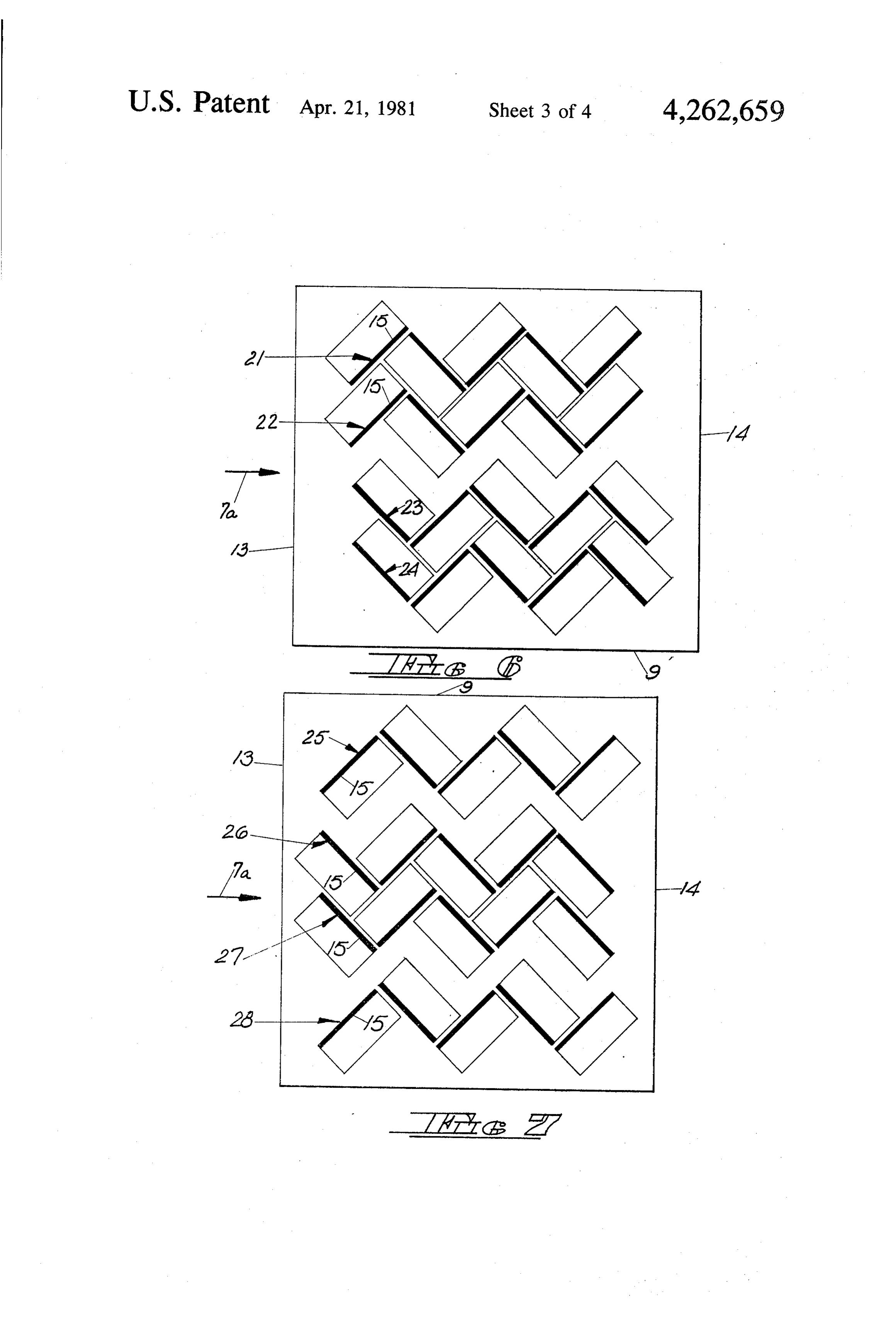
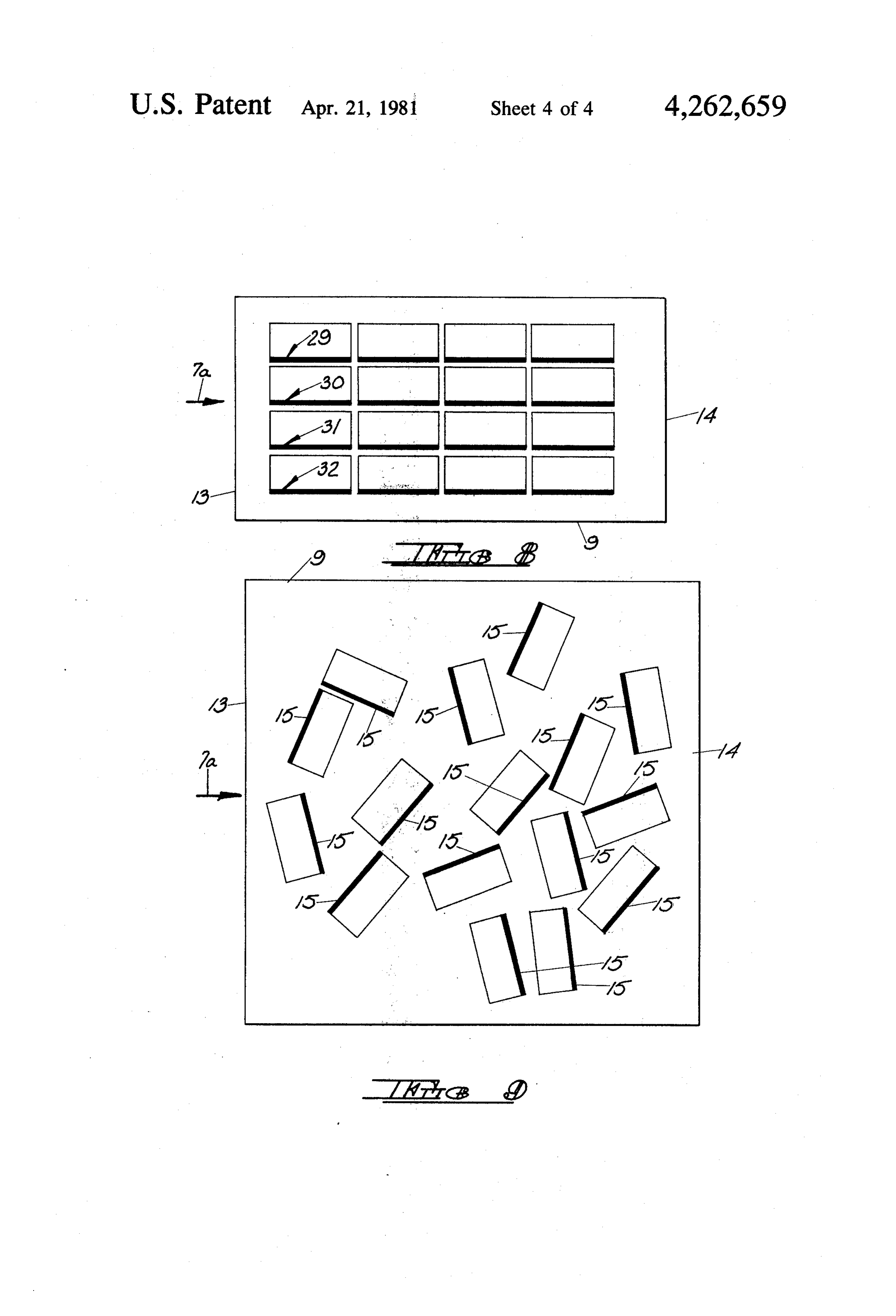
ods of construction require that the fins and plate be Further features of the invention will become appar separately fabricated, and that an additional fabrication ent from the detailed description which follows: step be required to join the fins and plate together, significantly decreasing the cost effectiveness of such BRIEF DESCRIPTION OF THE DRAWING flat-plate collectors. FIG. 1 is a perspective view of a solar collector utiliz The present invention is directed to a solar radiation 65 ing the solar radiation absorbing panel of the present absorbing panel for use with a fluid heating solar collec invention.
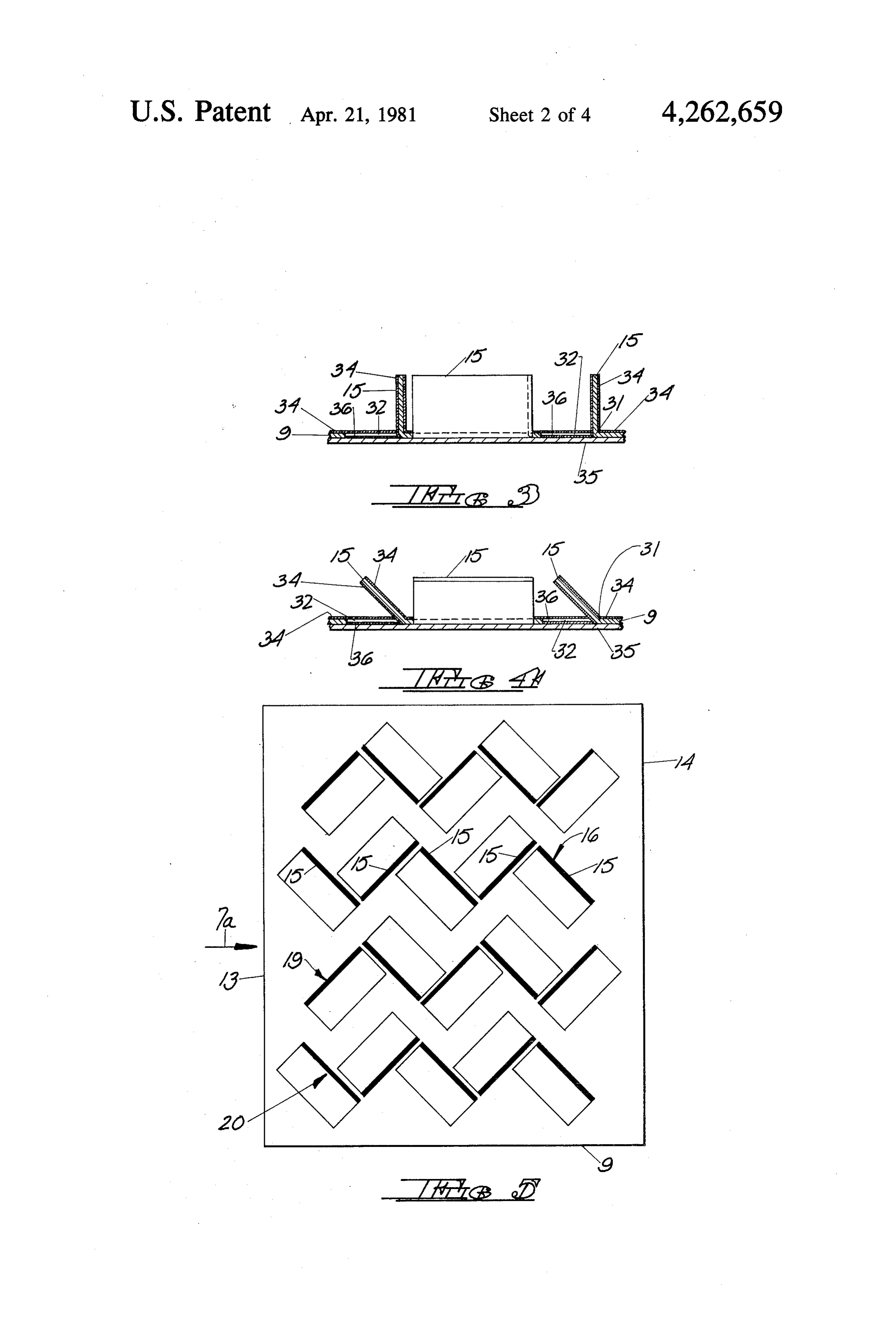
tor of the type described above including an absorbing FIG. 2 is a top elevation, view of a partially com plate having means projecting upwardly from the upper pleted panel of the present invention.
Page 7scan →
FIG. 3 is a fragmentary cross sectional view taken 9. The panel further includes a first series of tab mem along section line 3-3 of FIG. 2. bers, shown generally at 16, consisting of a plurality of FIG. 4 is a fragmentary cross sectional view taken individual tab members 15 arranged in end-to-end rela through the panel of the present invention illustrating tionship, which extends generally between inlet edge 13 angularly disposed tab members. and outlet edge 14 of panel 1. In other words, the indi FIG. 5 is another embodiment illustrating an alternate vidual tab members 14 are arranged to form the sinuous tab member configuration. ly-shaped series of tab members by positioning the tab FIG. 6 is a top plan view of another embodiment members perpendicularly to each other such that adja illustrating an alternate tab member configuration. cent vertical edges are substantially parallel but not FIG. 7 is a top plan view of another embodiment 10 contiguous, thereby forming a zig-zag-shape of adjoin illustrating an alternate tab member configuration. ing tab elements extending between the inlet and outlet FIG. 8 is a top plan view of another embodiment of collector 2. A second series of tab members 17 is illustrating an alternate tab member configuration. similarly formed by individual tab members 15 arranged FIG. 9 is a top plan view of another embodiment in end-to-end relationship, such that the spacing be illustrating an alternate tab member configuration. 15 tween the first series of tab members 16 and the second DETAILED DESCRIPTION series of tab members 17 is substantially constant, with the space between the parallel series of tab members
The solar radiation absorbing panel of the present forming a fluid passageway extending between the col invention, shown generally at 1, is illustrated in FIG. 1 lector inlet and outlet. If desired, a third series of tab in connection with a typical flat plate solar collector 20 members 18 may also be formed of individual tab mem shown generally at 2. As is well known in the art, such bers 15 placed in end-to-end realitionship, with the third flat-plate solar collectors generally include a box-like series being positioned in spaced relationship with the housing 3 having spaced parallel side walls 4 and spaced second series of tab members 17, thereby forming parallel end walls 5 and 6. End wall 5 generally forms a spaced parallel fluid passageways formed by the spaced fluid inlet for admitting a working fluid, such as air, 25 parallel sinuously-shaped series of tab members. water or the like, into collector 2 in the direction illus It will be observed in this arrangement that each tab trated by directional arrow 7. Similarly, end wall 6 member 15 is arranged at an angle of approximately 45 forms an outlet for exhausting heated working fluid with respect to inlet edge 13, and is oriented generally from the collector. A sheet 8 of solar radiation transmis to lie along a line extending between inlet edge 13 and sive material such as glass, plastic or the like, is posi 30 outlet edge 14, or in other words along a line extending tioned on the upper surface of collector 2 overlying between inlet edge 13 and one or the other of side edges panel 1 to admit solar radiation into the collector. 11 or 12. It will further be observed that the opposing In the embodiment of the invention illustrated in tab elements 15 of each series are arranged in staggered FIG. 1-FIG. 3, panel 1 comprises a substantially flat relationship by approximately one half their length. In plate-like base sheet 9 having a substantially planar 35 other words, a tab element 15 begins at approximately upper surface 10 bounded by spaced side edges 11 and the midpoint of the opposing tab element. 12, and spaced end edges 13 and 14. End edge 13 forms As best shown in FIG. 3, tab members 15 are substan the fluid inlet end of panel 1 as illustrated diagrammati tially perpendicular to the upper surface 10 of base sheet cally by direction arrow 7a, while end edge 14 forms 9. However, it is also considered to be within the scope the fluid outlet end of panel 1. In the preferred embodi of the present invention to angularly dispose tab mem ment illustrated, base sheet 9 may be rectangular in bers 15 with respect to surface 10 of base sheet 9 as shape, and constructed of a solar radiation absorptive illustrated in FIG. 4. In either event, the tab members material such as aluminum, steel or the like, and may provide additional collector surface area for collecting also be provided with solar radiation absorption en solar radiation reflected within the collector and pre hancing coating as will be described in more detail 45 vent reflection of solar radiation through the collector hereinafter. It is preferred that relatively light gauge cover, as well as act as turbulators to introduce turbu material be utilized for panel 1 in order to provide faster lance into the fluid stream passing among the tab mem response to direct or diffuse sunlight, and consequently bers to effectively remove heat from the tab members or higher heat absorption, especially on cloudy days. surface 10 of base sheet 9. It will also be observed that Panel 1 is provided with means projecting away from 50 the series of tab members may be arranged in different surface 10 of base sheet 9 for forming one or more fluid configurations to impart various types of flow patterns passageways for directing fluid from inlet edge 13 to to the fluid passing through the collector. For example, outlet edge 14. These means include a plurality of indi in the embodiment of FIG. 5, the individual tab mem vidual rectangular tab members 15 extending perpen bers 15 are arranged in end-to-end relationship to form dicularly away from surface 10 of base sheet 9. In a 55 a first sinuously shaped series of tab elements 16 in the preferred embodiment, tab members 15 are of substan manner described hereinabove. There is also provided a tially the same size and shape, and dimensioned to ex second series 19 of individual tab members 15 arranged tend from surface 10 of base sheet 9 to slightly beneath in end-to-end relationship, with adjacent tab members the lower surface of collector cover 8. This construc being perpendicular to each other, such that series 19 is tion limits the amount of fluid passing between the 60 positioned in opposing relationship so that the spacing upper edges of tab members 15 and the lower surface of between the first and second series of tab members is the cover, and restricts the flow of fluid through collec non-constant. In other words, opposing tab elements 15 tor 2 to the fluid passageways formed between the sinu are substantially perpendicular to each other so that the ous-shaped series of tab members 15 placed in end-to spacing between these tab members varies from a maxi end relationship. 65 mum as the inlet edge 13 of panel 9 to a minimum at As best shown in FIG. 1, each tab member includes a outlet edge 14 of panel 9. In this arrangement, as in the pair of substantially vertical spaced edges 15a and 15b, embodiment of FIG. 1-FIG. 3, adjacent tab members of extending away from the upper surface 10 of base sheet each series are perpendicular to each other and non 8 contiguous, with the tab members being perpendicular by separate or consecutive stamping and bending opera to the base sheet 9 and arranged at angles of approxi tions where some of the tab members are formed at one mately 45" with respect to inlet edge 13. time and some of the tab members are formed at a differ If desired, a third series 20 of individual tab members ent time.
15 arranged in end-to-end relationship may be posi As observed above, tab members 15 may be bent tioned in spaced relationship with second series 19 to perpendicularly to surface 10 of sheet 9 as illustrated in form another air passageway between the sinuously FIG. 3, or may be bent to form angular relationships shaped series of tab members. In the embodiment of with the base sheet surface. It will be observed that this FIG. 5, series 20 is positioned such that the spacing method of fabrication produces tab members 15 and between series 19 and 20 is non-constant. Additional 10 openings 32 which are non-contiguous, thereby furnish series of tab elements may be added as required to form ing connecting areas or lands 33 between adjacent open the necessary number of fluid passageways. ings and tab members, as shown in FIG. 2. In order to Another arrangement is illustrated in FIG. 6, where provide sufficient structural rigidity to panel 1, it is the sinuously shaped series 21 and 22 of adjoining indi preferred that the lands 33 between adjacent openings vidual tab elements 15 are of substantially constant 15 32 and between adjacent tab members 15 is at least one spacing, and the outermost sinuously shaped series 23 eighth of the shortest dimension of the tab member or and 24 of individual adjoining tab members 15 are ar opening.
ranged in constant spaced relationship. However, series In order to enhance the absorptivity of panel 1, the 22 and 23 are so arranged that the spacing between surface 10, as well as the surfaces of tab members 15 these tab elements is non-constant, thereby forming 20 may be provided with a coating 34 of black paint or three non-parallel fluid passageways extending between other solar radiation absorption enhancing material. the inlet and outlet of the panel. In a preferred embodiment, means are provided in the A further embodiment is illustrated in FIG. 7 where form of a substantially flat plate-like support sheet 35 the outermost adjacent series 25 and 26, and 27 and 28, underlying base sheet 9 to cover openings 32 and pre respectively, are arranged in non-constant spaced rela 25 vent fluid flow therethrough. In addition, the portions tionship, while the innermost adjoining series 26 and 27 of support sheet 35 coextensive with openings 32 may are positioned in constant spaced relationship, thereby be provided with a solar radiation absorption enhancing forming three non-parallel fluid passageways extending coating 36 the same or different from coating 34. Alter between the inlet and outlet of the panel. natively, base sheet 9 or support sheet 35, or both, may In the embodiment of FIG. 8, all of the tab members 30 themselves by constructed of a solar radiation absorbing 15 are parallel to each other and formed in four parallel material.
series 29-32 of adjoining tab members to form three It will be understood that various changes in the parallel spaced fluid passageways extending between details, materials, steps and arrangements of parts, the inlet and outlet of the panel. It will be observed that which have been described and illustrated in order to this arrangement lacks the sinuous shape of the previous 35 explain the nature of the invention, may be made by embodiments, and may be used in constructions where those skilled in the art within the principle and scope of minimal impedence to fluid flow is desired. the invention as expressed in the appended claims. Finally, in the embodiment of FIG. 9, the individual The embodiments of the invention in which an exclu tab members 15 are arranged randomly to provide a sive property or privilege is claimed are as follows: plurality of randomly positioned air passageways 40 1. A solar radiation absorbing panel for use with a among the tab members. fluid heating solar collector of the type having a box As described above, solar radiation absorbing panels like enclosure dimensioned to accept said panel and are known which require that continuously constructed including a cover overlying said panel transmissive to vertically positioned fins be separately attached to the solar radiation, said panel comprising: underlying base sheet in one or more separate fabrica 45 a substantially flat plate-like base sheet of solar radia tion steps to complete the panel. However, the solar tion absorptive material having a substantially pla radiation absorbing panel 1 of the present invention is nar surface bounded by spaced side and end edges, constructed in such a way as to eliminate the separate said end edges forming the fluid inlet and outlet, fabrication steps required by conventional solar radia respectively, of said panel; and tion absorbing panels. 50 means projecting away from said surface of said base In the present invention, the substantially flat plate sheet for forming at least one fluid passageway for like base sheet 9 is severed along a plurality of C-shaped directing fluid from said inlet to said outlet, said non-contiguous continuous lines 30 as illustrated in means including a plurality of individual tab mem FIG. 2, leaving a portion 31 of the base sheet attached bers extending away from said surface of said base between the ends of each of the lines of severence 30 to 55 sheet, each of said tab members being formed by form a fold or bend line. If desired, the fold line 31 may severing said sheet along a continuous line leaving be scored or grooved to facilitate bending of the tab a portion of said base sheet attached between the member. Each attached portion is then bent away from ends of said severed line and bending said tab mem surface 10 of sheet 9 to form the plurality of upstanding ber along said attached portion away from said rectangular-shaped tab members 15 and openings 32 of 60 surface leaving an opening in said base sheet, the substantially the same size and shape as the tab mem spaces between some at least of said tab members bers. It will be understood that members of different forming said fluid passageways, each of said tab shapes such as semicircular, square, trapezoidal, etc., members including spaced edges extending away may be formed by properly arranged severence and from said base sheet, said plurality of tab members bend lines. Furthermore, it will be observed that the tab 65 comprising a first series of tab members arranged in members 15 may be rapidly and easily formed in this end-to-end relationship extending generally be manner by a single stamping and bending operation tween said inlet and outlet, and a second series of where the tab members are formed simultaneously, or tab members arranged in end-to-end relationship 9 spaced from said first series of tab members to form perpendicular to said base sheet and substantially ar said passageway between said first and second ranged at angles of 45 with respect to said inlet edge, series of tab members. said tab members being rectangular and of substantially 2. The panel according to claim 1 wherein some at the same size and shape as each other and as said open least of said tab members are dimensioned to extend 1S.
from said surface of said base sheet to slightly beneath 5. The panel according to claim 14 wherein said first the collector cover to limit fluid passing therebetween. and second series of tab members are positioned in op 3. The panel according to claim 1 wherein some at posing relationship such that the spacing between said least of said tab members are perpendicular to said sur first and second series of tab members is non-constant. face of said base sheet. 10 23. The panel according to claim 22 wherein adjacent 4. The panel according to claim 1 wherein said tab tab members of each of said series are perpendicular to members are rectangular. each other and non-contiguous, said tab members being 5. The panel according to claim 1 wherein said tab perpendicular to said base sheet and substantially ar members are of substantially the same size and shape. ranged at angles of 45 with respect to said inlet edge, 6. The panel according to claim 1 wherein said tab 15 said tab members being rectangular and of substantially members and said openings are of substantially the same the same size and shape as each other and as said open size and shape. lings.
7. The panel according to claim wherein some at 24. The panel according to claim 1 including a third least of said tab members are oriented to lie along lines series of tab members arranged in end-to-end relation extending between said inlet edge and said outlet edge. 20 ship and positioned in spaced relationship with said 8. The panel according to claim 1 wherein some at second series of tab members.
least of said tab members are oriented to lie along lines 25. The panel according to claim 24 wherein said extending between said inlet edge and one of said side third series of tab members is parallel to at least one of edges. said first and second series of tab members. 9. The panel according to claim 1 wherein some at 25 26. The panel according to claim 25 wherein said least of said tab members are arranged in spaced parallel first, second and third series of tab members are sinu relationship. ously shaped.
10. The panel according to claim 1 wherein said tab 27. The panel according to claim 26 wherein the members are non-contiguous. spacing between said series of tab members is substan 11. The panel according to claim 1 wherein said tially constant.
openings are non-contiguous. 28. The panel according to claim 26 wherein the 12. The panel according to claim 1 wherein some at spacing between adjacent series of tab members is non least of the tab members of said first series are parallel to COnStant.
some at least of the tab members of said second series. 29. The panel according to claim 26 wherein the 13. The panel according to claim 1 wherein said tab 35 spacing between one set of adjacent series of tab mem members of said first series are parallel to each other bers is substantially constant and the spacing between and said tab members of said second series are parallel the other set of adjacent series of tab members is non to each other. COnstant.
14. The panel according to claim 1 wherein said first 30. The panel according to claim 1 wherein said tab and second series of tab members are sinuously shaped. members are rectangular and of substantially the same 15. The panel according to claim 14 wherein adjacent size and shape as each other and said openings, and tab members of each series are perpendicular to each wherein the spacing between adjacent openings and other. between adjacent tab members is at least one eighth of 16. The panel according to claim 14 wherein adjacent the shortest dimension of said tab member. edges of said tab members are non-contiguous. 45 31. The panel according to claim 1 including means 17. The panel according to claim 14 wherein said tab covering said openings to prevent fluid flow there members are arranged substantially at angles of 45 with through.
respect to said inlet edge. 32. The panel according to claim 31 wherein said 18. The panel according to claim 14 wherein the means comprises a substantially flat plate-like support spacing between said first and second series of tab mem 50 sheet underlying said base sheet. bers is substantially constant. 33. The panel according to claim 32 wherein the 19. The panel according to claim 18 wherein the portion of said support sheet coextensive with said opposing tab members of each series are arranged in openings in said overlying base sheet is solar radiation staggered relationship. absorbing.
20. The panel according to claim 18 wherein said 55 34. The panel according to claim 1 including said opposing tab members are staggered by approximately enclosure and cover, said enclosure incorporating said one half their length. panel and supporting said cover in overlying relation 21. The panel according to claim 20 wherein adjacent ship with the tab member containing surface of said tab members of each of said series are perpendicular to panel.
each other and non-contiguous, said tab members being 60 sk k k
Provenance
- Collection
- Patents citing this work
- Pages
- 9
- Method
- pdftotext (the PDF's own text layer) + pdftoppm 300dpi page scans
- Patent office record
- patents.google.com →
- Source
- Google Patents citing-documents table
- Assignee
- Valley Industries, Inc.
- Published
- 1981-04-21
- Transcribed from
- patentimages.storage.googleapis.com →