

patent · US4184481A
Directional self-supporting pyramid shaped hot water solar absorber
22 January 1980
Text
Page 1bibliographic recordscan →
United States Patent (19)
Tornquist
54 DIRECTIONAL SELF-SUPPORTING
PYRAMID SHAPED HOT WATER SOLAR
ABSORBER
76 Inventor: August Tornquist, 125 Barclay Ave.,
Staten Island, N.Y. 10312
Related U.S. Application Data 63 Continuation-in-part of Ser. No. 820,467, Aug. 1, 1977, abandoned.
(51) Int. Cl’................................................. F24J 3/02 (52) U.S.C. .................................... 126/422; 126/447;
3,822,692 7/1974 Demarest ............................. 126/271 4,084,573 4/1978 Shubert ................................ 126/270 4,108,157 8/1978 Gorniak ............................... 126/271 4,132,221 1/1979 Orillion ................................ 126/271 4,149,525 4/1979 Prado ................................... 126/271 Primary Examiner-James C. Yeung
Attorney, Agent, or Firm-Gloria K. Koenig
A solar absorber to be mounted on the roofs of build ings, the absorber having the form of a pyramid with the heat absorbing elements mounted across the upward extending faces of the pyramid and the base formed to conform to the contour of the roof so that the solar absorber may be fixedly mounted on the roof of a build ing.
In a modified form of my invention each face of the pyramid is independently equipped with a heat sensor which is electrically connected to a water valve and water circulator so that water circulates only through the faces exposed to sunlight.
0 Claims, 16 Drawing Figures
Drawings
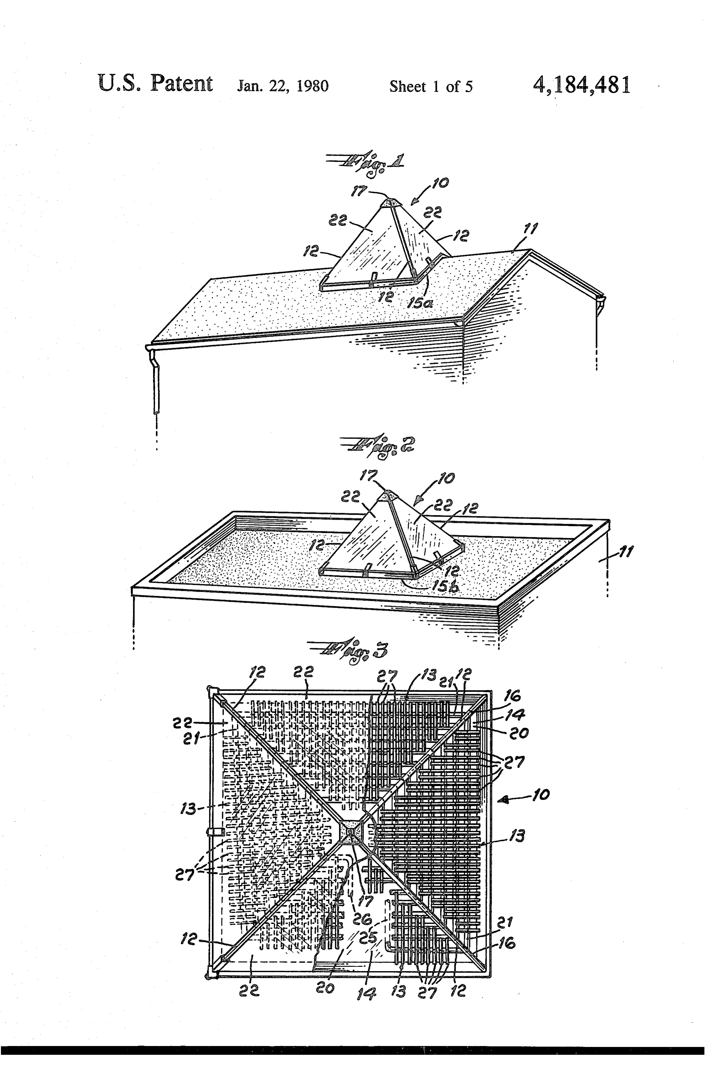
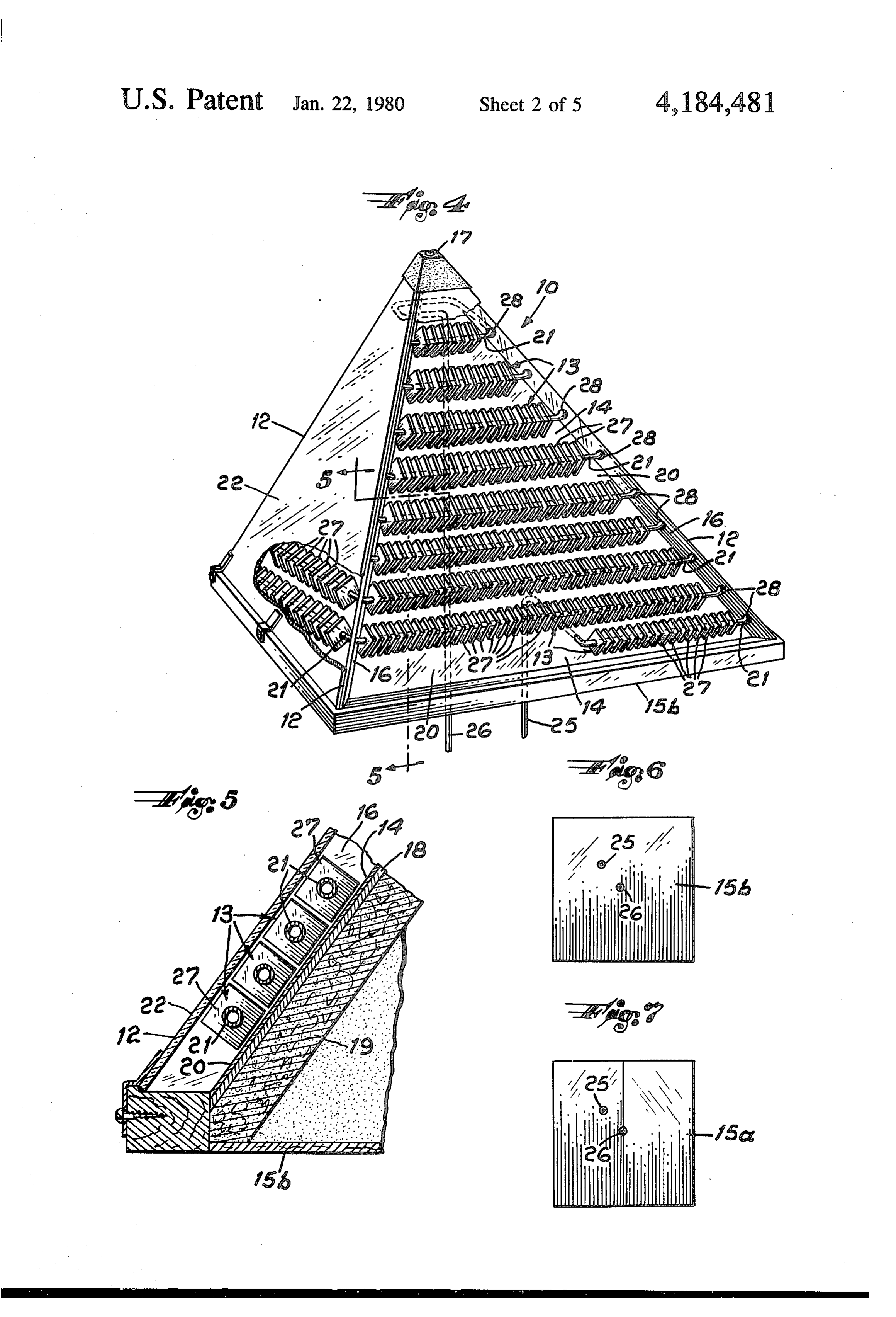
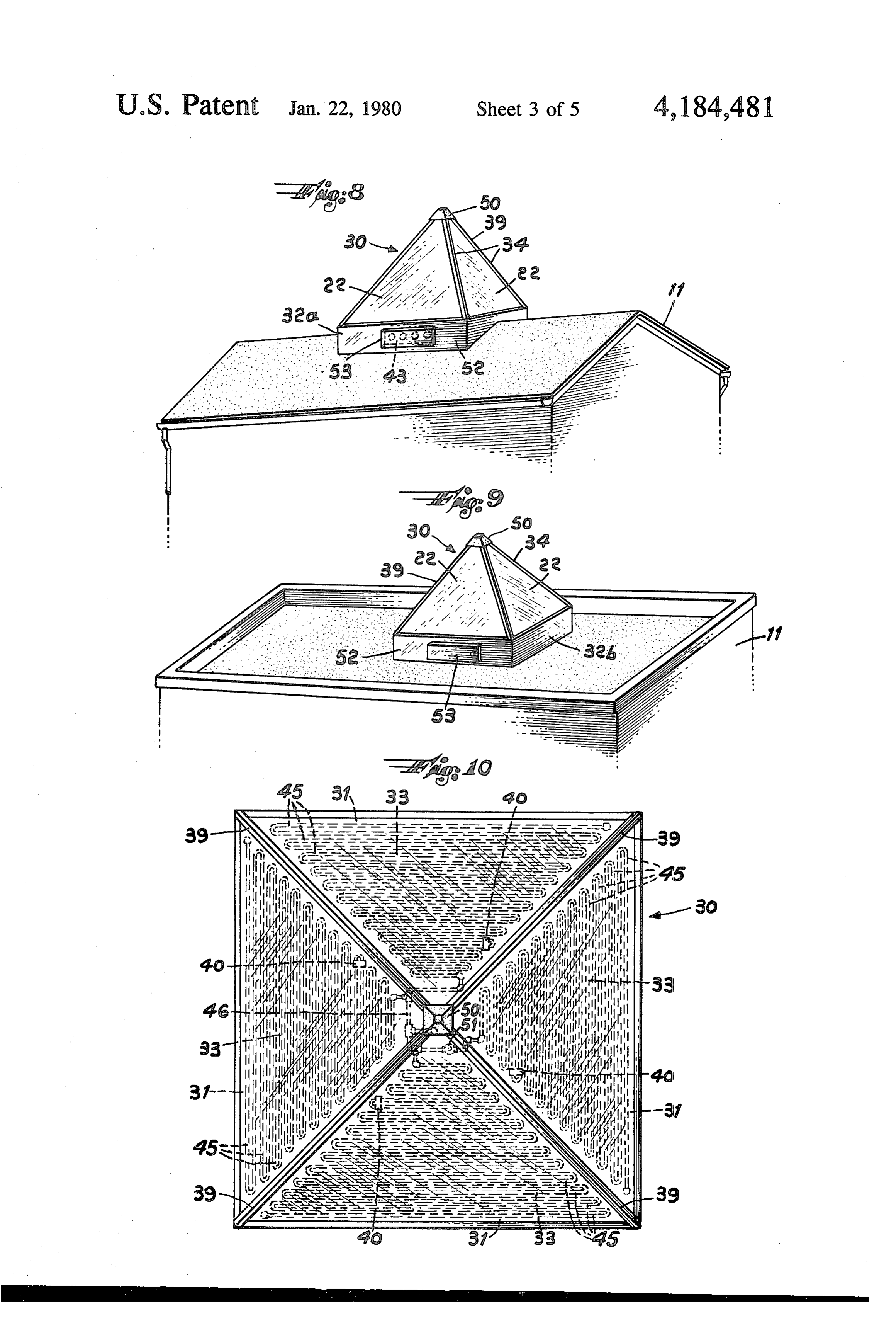
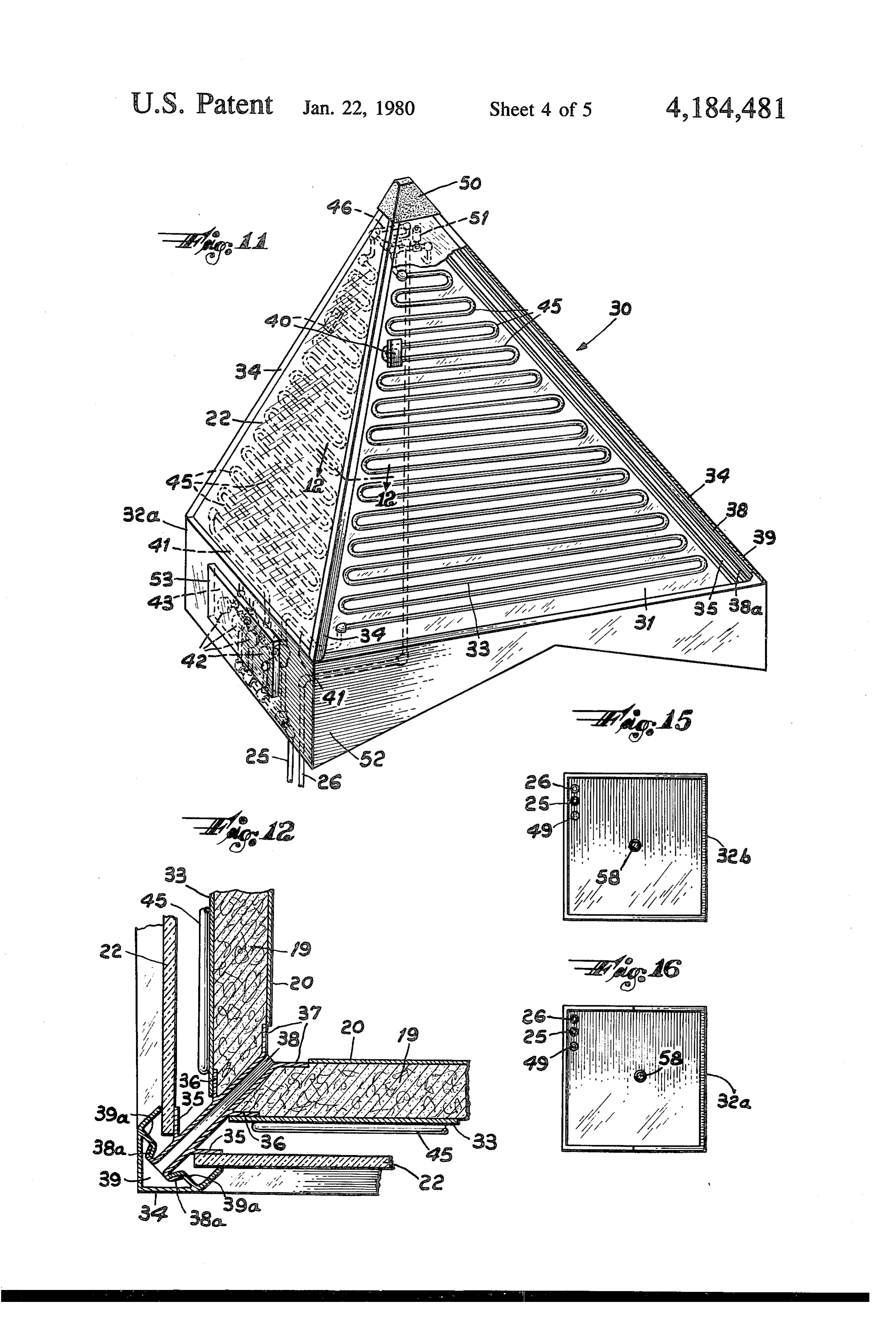
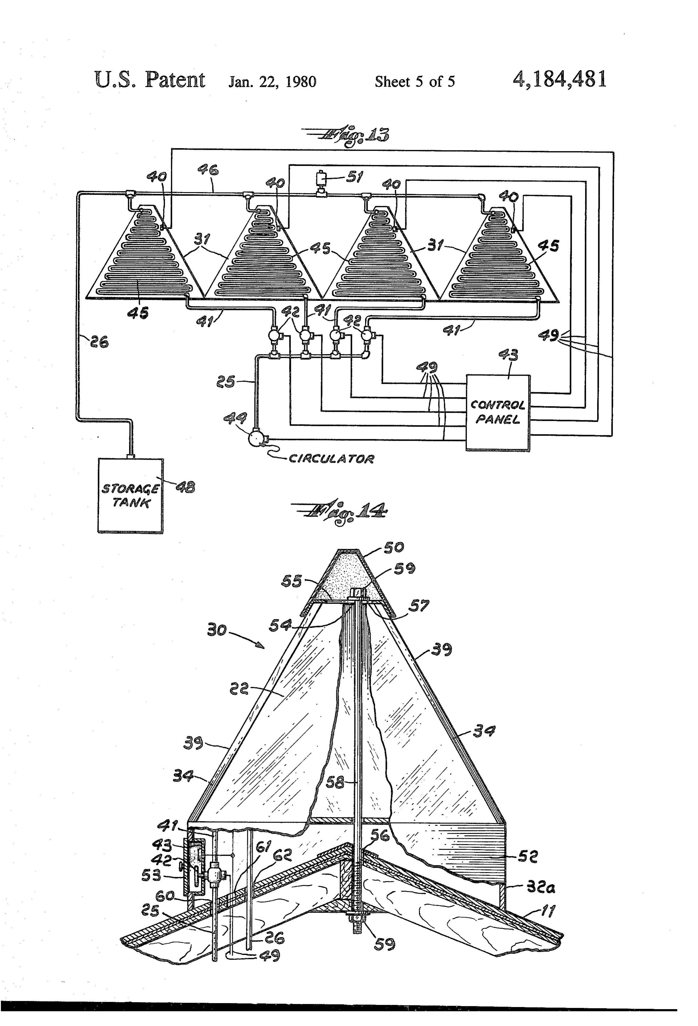
FIG. 10 is a top plan view of the device shown in
Page 2drawing sheetscan →
Page 3drawing sheetscan →
Page 4drawing sheetscan →
Page 5drawing sheetscan →
Page 6drawing sheetscan →
Page 7scan →
substantially all buildings regardless of latitude or the
DIRECTIONAL SELF-SUPPORTNG PYRAMID directional orientation of the building. SHAPED HOT WATER SOLAR ABSORBER Another object of this invention is to provide a very efficient solar absorber. Tests indicate that the use of
CROSS REFERENCE finned copper absorbing elements provide up to several This application is a continuation in part of pending times the amount of absorbing surface on a square foot application Ser. No. 820,467 filed Aug. 1, 1977, aban to square foot basis as compared to flat plate collectors, doned. without the need for added baffles to prevent internal convection.
BACKGROUND OF THE INVENTION 10 In the modified form of my invention the heat absorb (1) Field of the Invention ing elements are pressed waterway bonded copper, This invention is a solar absorber for use to heat hot aluminum or stainless steel or alternatively are made of water by means of the sun's rays and designed to be copper tubing bonded to copper or aluminum heat mounted on the roofs of buildings, the solar absorber transfer flat surfaces. Panels of these absorbing elements elements being mounted in the form of a pyramid, with 15 can be manufactured ready to install and have been the base of the pyramid designed to conform to the found to be easy to handle and efficient. contour of a roof. In the first form of my invention, Another object of this invention is to provide a solar finned copper absorbing elements are connected in se absorber which is relatively easy to mount and to main ries, with the absorber having one heat sensor electri tain.
cally connected to one water valve and water circula 20 These and various other objects and advantages of tor, with the cold water circulating around the entire this invention will be more fully apparent from a consid absorber. In my modified absorber, the heat absorbing eration of the following description, drawings and ap elements are pressed waterway bonded copper, alumi pended claims.
num or stainless steel or alternatively are made of cop per tubing bonded to copper or aluminum heat transfer 25 BRIEF DESCRIPTION OF THE DRAWINGS flat surfaces. Each panel is equipped with its own heat FIG. 1 is a perspective view of the hot water solar sensor which is electrically connected through a con absorber trol panel to a zone water valve and to a water circula mounted according on a to this invention showing the device house having a peaked roof. FIG. 2 is a tor, so that water is circulating through only those pan perspective view of the invention showing it mounted els which are exposed to the sun. 30 on a house having a flat roof.
(2) Description of the Prior Art FIG. 3 is a top plan view.
Most commercially available hot water solar absorb FIG. 4 is a side perspective view of the absorber ers available for home use are flat plate absorbers. How showing the placement of the absorbing elements. ever, in a majority of existing homes, flatbed absorbers are not adaptable to the roof angle or to the north-east 35 4. FIG. 5 is a sectional view taken on line 5-5 of FIG. south-west orientation of the building. In homes where the ridge pole of the roof runs in a north-south direc FIG. 6 is a bottom plan view of the base of the ab tion, a conglomeration of odd angle brackets would be sorber designed for use on flat roofs. required to mount the flat bed absorbers in such a way FIG. 7 is a bottom plan view of the base of the ab as to be moderately effective in catching the sun's rays. sorber designed for use on peaked roofs. Most solar contractors do not want to construct these FIG. 8 is a perspective view of a modified version of ungainly types of arrangements and very few home this invention showing the device mounted on a house owners would consent to have such ugly structures on having a peaked roof.
their roofs. Further, known types of solar absorbers do FIG. 9 is a perspective view of a modified version of not permit the economical installation of these devices 45 the invention showing it mounted on a house having a on a great many homes. flat roof.
Summary of the invention
FIG. 10 is a top plan view of the device shown in
It is an object of this invention to provide a hot water FIG. 11 is a side perspective view of the device solar absorber having an upper part shaped as a pyramid 50 shown in FIG. 8.
and a lower part or base made with either a flat surface FIG. 12 is a sectional view taken on line 12-12 of for mounting on flat roofs or a wedged shaped base for FIG. 11.
mounting on peaked roofs. FIG. 13 is a schematic diagram of the heat sensor The heat absorbing elements themselves are those electrical connections and water line connections of the which are well known in the art, the invention being the 55 device shown in FIG. 8.
form, arrangement and connection of the known types FIG. 14 is a sectional view of the device shown in of absorbing elements into the upward extending faces FIG. 8 showing the attachment to the roof of a building. of a pyramid, thus providing a single fixed unit, in FIG. 15 is a bottom plan view of the device shown in which one or more of the faces will take the sun's rays FIG. 8 designed for use on flat roofs. throughout the day. The pyramid, unlike a flat plate 60 FIG. 16 is a bottom plan view of the device shown in collector, will take the full morning sun at almost right FIG. 8 designed for use on peaked roofs. angles to the east side. At midday the absorber will take DESCRIPTION OF THE PREFERRED the full sun on the west with angle absorption on the EMBODIMENTS south and west. An exception would be in far northern latitudes where the noon sun would not strike the north 65 Referring now specifically to the drawings, the nu side. It is therefore a further object of this invention to meral 10 designates the heat absorber. The heat ab provide an all directional, self-supporting unit which sorber is constructed by connecting a plurality of heat requires no external brackets and which can be used on absorber elements 13 to form a triangular shaped lateral 8 face 14 or panel extending upwardly from a base 15. A form a pyramid which tilts toward a predetermined plurality of triangular faces 14 are connected along their desired direction.
upward extending or lateral edges 12 by a flashing strip The size of the faces of the pyramid will vary accord 16 to form a pyramid having an upward extending ver ing to the requirements of the dwelling. Further, the tex 17. angles formed by the lateral edges of the pyramid may A typical absorber panel 14 is shown in FIG. 4. A vary with the latitude in which the device will be used, sectional view of a part of a typical absorber panel 14 is but generally the base angles of the pyramid will be shown in FIG. 5. A sheet of plywood 18 is covered with approximately 51 degrees.
a sheet of foam insulating material 19 on its inside face. 10 The base 15 of the pyramid is formed to fit the config The outer surface of the plywood sheet is covered with uration of the roof of the building 11 on which the solar sheet aluminum 20. The absorber elements 13 are absorber will be placed. As shown in FIG. 1, the base mounted on the outer face of the sheet aluminum 20. 15a is wedge-shaped to fit onto a peaked roof, the angle The absorber elements 13 may be constructed of finned of the wedge depending on the shape of the roof. Foam copper, pressed copper or stainless steel tubing or they rubber can be attached to the edges of the wedge may be made by using teflon baffles over aluminum, 15 shaped base to provide a unit which can be mounted on copper or stainless steel tubing. In FIG. 5 the copper peaked tile roofs. Heretofore it has been practically tubing is indicated by numeral 21 and the fins by nu A impossible to mount a solar heater on a peaked tile roof. meral 27. The absorber elements 13 are then covered plan view of an equilateral wedge is shown in FIG. 7. with a protective sheet 22 made of glass, double glass, 20 The base 15b as shown in FIGS. 2 and 6 is a flat surface designed to rest on flat roofs. In either case, after the plastic, teflon or fiberglass. The absorber elements 13 and the sheet aluminum 20 are sprayed with an absorp device is hoisted onto the roof of a building it is affixed tion enhancing coating such as 3M Nextel or an equiva in place by brackets which are not shown in the draw Ings.
lent spray coating (not shown in drawings). A modified version of my invention is shown in The absorber panel shown in FIG. 5 may be con FIGS. 8 through 14, where the numeral 30 designates structed with " (1.2 cm.) plywood sheet, 1" (3.7 cm.) 25 the modified heat absorber and with similar parts identi foam insulation, and 3" (2 cm.) copper convector alumi fied by the same num finned tubes, although it is obvious that other sizes lar shaped heat numerals absorber as above. Preformed triangu panels 31 of predetermined may be used with satisfactory results. size, extend upwardly from a base 32 having side walls In testing various absorber elements, it has been 30 52 which are mitered to conform to the contours of a found that when using finned copper absorber elements, roof of a building 11.
convection under the glass is greatly reduced, thus preventing re-radiation on a side not receiving the di 31 Ais sectional view of a part of a typical absorber panel rect rays of the sun. An advantage of using a finned tube are triangular FIG.
shown in 12. The heat absorbing elements 33 sheets preformed to have water lines absorber element is that a great number of fins will 35 running through a flat heat transfer surface, such as always be facing the sun's direct angle and there will pressed waterway bonded copper, aluminum or stain not be as much of a re-radiating effect as from a flat less steel or alternatively copper tubing bonded to cop surface in the morning and evening. per or aluminum heat transfer flat surfaces. In the draw The tubes 21 of the absorber element 13 are con ings, the pressed or bonded tubing or waterway is indi nected in series at the lateral edges 12 of the triangular cated by the numeral 45. Each obsorber element 33 is panel faces 14 by pipe elbows (not shown) to form a covered on the outer face with a protective heat trans continuous run of tubing from the lower part of the mitting sheet 22 made of glass, double glass, plastic, pyramid to an area near the vertex 17, as shown in FIG. teflon or fiberglass. The protective sheet may be trans 3. The pipe elbows pass through holes 28 formed in the parent or translucent and tinted. Each absorber element flashing strips 16 mounted on the lateral edges of the 45 33 is backed by a sheet of insulation material 19 such as panel faces. The flashing 16 is also used to support the 1 inch (3.7 cm.) foam insulation, which is backed by a protective sheets 22 of glass, plastic, teflon or fiberglass sheet of aluminum 20.
which cover the absorber elements 3. The components of the heat absorber panel 31 are The absorber elements 13 are connected to a cold connected along their upwardly extending or lateral water inlet pipe 25 and a hot water outlet pipe 26 by 50 edges 12 by a slide down corner locking extrusion 34 well known plumbing techniques, with a heat sensor having a corner strip 39 formed with inward facing electrically connected to open the cold water valve and projections 39a at the ends and a center support 38 to activate a water circulator, the hot water thereafter formed with two outward facing projections 38a at the being pumped into a storage tank or heating system for forward end, the corner projections and center support house heating or domestic hot water. A standard type 55 projections being formed to interlock. Three pairs of air eliminator 51 is mounted in the hot water line separate extrusions 35, 36, 37 extend outwardly from toward the top of the pyramid (shown in FIG. 11). the center support at a predetermined angle to form A plurality of heat absorber elements 13 as described three pairs of channels into which the lateral edges of are formed and arranged in predetermined sizes to form two sheets of protective material 22, absorber elements a triangular lateral face 14 or panel when connected, a 60 33 and the insulation 19 backed by aluminum sheeting plurality of such lateral faces being arranged and con 20 are fitted, respectively. As is well known in the art, nected to form a pyramid. The device shown in the the projections 39a of the corner strips 39 are inter drawings, which is my preferred form, is a four sided or locked with the projections 38a of the center support quadrilateral regular pyramid, all of the lateral faces 38, bringing together two panels with the corner strip being congruent isosceles triangles. However, it is obvi 65 forming the angle corner of each lateral edge of the ous that the device can be constructed with three or pyramid.
more equal lateral faces or it may be formed with three A heat sensor 40 is operably mounted in the face of or more faces having lateral edges of unequal length to each absorber element 33. The lower end of the copper 9 water heating tubing in each heat absorbing element 33 for the passage of the electrical lines 49 and an opening is connected to its own cold water line 41 which in turn 62 for the passage of the hot water outlet 26. The same is connected to a zone water valve 42 located in a con method can be used for flat or pitched roofs. trol panel 43 installed in one side wall 52 of the base32 It will thus be seen that I have provided a new and of the heat absorber. Each heat sensor 40 is electrically 5 improved all directional, hot water solar absorber. connected through a control panel 43 to one water I claim:
valve 42 and to a water circulator 44. When the sun hits 1. A pyramidal water solar absorber comprising: an absorber panel 31 the heat sensor 40 operates to open (a) a base having upwardly extending side walls; both the water valve 42 controlling the water flow to (b) a plurality of triangular panels extending up the particular panel and the water circulator 44. Cold 10 wardly from the base, the panels forming the lat water passes through the copper tubing or waterways eral faces of a pyramid, the pyramid having an 45 of the heat absorbing elements 33 and warm water is opening at its vertex, said panels being formed in collected at the point near the top of the pyramid in a predetermined sizes, each panel comprising: hot water collection pipe 46 or manifold which is con (1) an outer layer of heat transmitting protective nected in series to the waterway lines 45 of the other 15 material;
heat absorber elements. The hot water then drains (2) a middle layer of heat absorber elements having down through a single hot water outlet line 26 to a water heating tubing in contact with a metal heat storage tank 48. The process is shown schematically in transfer surface;
FIG. 13 wherein electrical connections are indicated by (3) an inner layer of insulation material. the numeral 49. 20 (c) connecting means to attach the lateral edges of the An air eliminator 51 is mounted in the hot water panels;
collection pipe 46 and functions to vent any air that is in (d) a metal cap removably mounted on the vertex of the water lines. the pyramid;
It has been found that for a four sided heat absorber, (e) a heat sensor operably mounted in each panel; four 24 volt zone valves and a 1/20th horsepower circu 25 (f) a cold water supply line; lating pump operate in a satisfactory manner. (g) a plurality of electrically operated water valves; The independent operation of each heat absorbing (h) a plurality of cold water connection pipes, leading panel increases the efficiency of the heat absorber as from the cold water supply line into each water water is not being pumped through a panel which is not valve and out of each water valve to the lower end being warmed by the sun, where the warm water would 30 of the water heating tubing of an absorber element, tend to lose some of its heat. When the sun is high in the each absorber element being connected to its own sky, all of the heat sensors would be activated and all water valve;
the panels will operate. When the sun is low in the sky, (i) a water circulating pump, each heat sensor being the heat sensor in the shade cuts out and closes the electrically connected to a water valve and to the water valve to the shaded panel. The water circulator 35 water circulating pump;
operates until the last sensor cuts off. (j) a hot water collection pipe connected in series to The vertex of the absorber panels is cut off to forman the upper ends of the water heating tubing; opening 54 at the top of the pyramid which is covered (k) an air eliminator mounted in the hot water collec with a removable metal cap 50, preferably made of tion pipe;
aluminum. The cap 50 can be removed to gain access to 40 (l) a hot water outlet pipe leading from the hot water the piping inside the pyramid. collection pipe to storage. The base32 of the pyramid has side walls and an open 2. A solar absorber as set out in claim 1 where the top to which the absorber panels are attached by clips bottom of the base is a flat surface. (not shown). The bottom of the base can be flat 32a or 3. A solar absorber as set out in claim 1 where the wedge shaped 32-b as described above. and as shown in bottom of the base is in the form of a wedge. perspective in FIGS. 8 and 9 and in plan view in FIGS. 45 4. A solar absorber as set out in claim 1 where all the 15 and 16. My preferred form is a square base and a four lateral faces of the pyramid are congruent isosceles sided regular pyramid, but as discussed above the de triangles.
vice may be constructed in other ways. 5. A solar absorber as set out in claim 4 where the A control box or panel 43, which is installed in one of pyramid has four lateral faces.
the side walls 52 of the base, contains all of the water 50 6. A solar absorber as set out in claim 5 where the and electrical connections. All of the plumbing and base angles of the lateral faces are approximately fifty electrical connections are concealed. The panel has a one degrees.
door 53 to protect the valves and electrical connections. 7. A solar absorber as set out in claim 1 where the In practice, the control panel is installed and all inside heat transmitting protective material is selected from a piping done with the exception of the last panel. The 55 group consisting of glass, double glass, plastic, teflon or final connections are then made at the control panel and fiberglass.
through the removable cap. 8. A solar absorber as set out in claim 1 where the The modified device is very simple to install, as heat absorber elements are pressed waterway bonded shown in FIG. 14. A metal plate 55 is mounted across metal, wherein the metal is copper, aluminum, or stain the opening 54 at the top of the absorber panels 31. 60 less steel.
Matching holes 56, 57 are drilled through the roof of a 9. A solar absorber as set out in claim 1 where the house 11 and the metal plate 55, respectively. A long heat absorber elements are copper tubing bonded to threaded rod 58 is passed through the roof 11 and metal metal heat transfer flat surfaces, wherein the metal is plate 55 and the threaded rod is fastened in place by copper or aluminum.
standard means, such as a stud plate, washer and nut, 65 10. A solar absorber as set out in claim 1 where a shown generally by the numberal 59. Three other open control panel is mounted in a side of the base to contain ings are drilled through the roof, namely an opening 60 all water and electrical connections. for the passage of the cold water line 25, an opening 61 k e t
Provenance
- Collection
- Patents citing this work
- Pages
- 9
- Method
- pdftotext (the PDF's own text layer) + pdftoppm 300dpi page scans
- Patent office record
- patents.google.com →
- Source
- Google Patents citing-documents table
- Assignee
- August Tornquist
- Published
- 1980-01-22
- Transcribed from
- patentimages.storage.googleapis.com →