

patent · US4188278A
Apparatus for degerminating fluids
12 February 1980
Text
Page 1bibliographic recordscan →
United States Patent (19)
Reis et al.
54 APPARATUS FOR DEGERMINATING
FLUIDS
Inventors: A. Reis, Munich; N. Kirmaier,
Aschheim; M. Schöberl, Prien, all of
Fed. Rep. of Germany Assignee: Institut fir Biomedizinische Technik, Munich, Fed. Rep. of Germany
(30) Foreign Application Priority Data
52 U.S. C. .................................... 204/268; 204/149;
3,335,078 8/1967 Mehl ................................ 204/149 3,625,884 12/1971 Waltrip ... ... 204/149 X 3,648,668 3/1972 Pacheco ........................... 204/129 X
OOOOOOOOOOOO
OOOOOOOOOOO
OOOOOOOOOOOO
OOOOOOOOOOO
8 OOOOOOOOOO
OOOOOOOOOOOO
3,767,542 10/1973 Carlson .................................. 204/98 3,843,507 10/1974 Kwan ......, 204/149 X 3,865,710 2/1975 Phipps .............................. 204/152 X 3,923,629 12/1975 Shaffer ............................. 204/149 X
Primary Examiner-Arthur C. Prescott
Attorney, Agent, or Firm--Donald Brown
An apparatus for degerminating fluids by the use of an electrolytic cell, a pair of main electrodes opposed in the electrolytic cell to each other, a voltage source connected to the main electrodes, and a plurality of auxiliary electrodes disposed between the main elec trodes. The main electrodes are biased in such a way that the fluid flows through a region of varying poten tial thereby effectively increasing the degerminating rate of the cell. The main electrodes cover the entire cross section of flow, they are provided with openings
to allow the passage of the fluid. The auxiliary elec trodes may be connected to parts of the overall voltage thereby providing an electrolytic cell which may be directly powered by solar energy.
9 Claims, 4 Drawing Figures
SSSSSSSSSSs.
Drawings
Page 2drawing sheetscan →
Page 3drawing sheetscan →
Page 4scan →
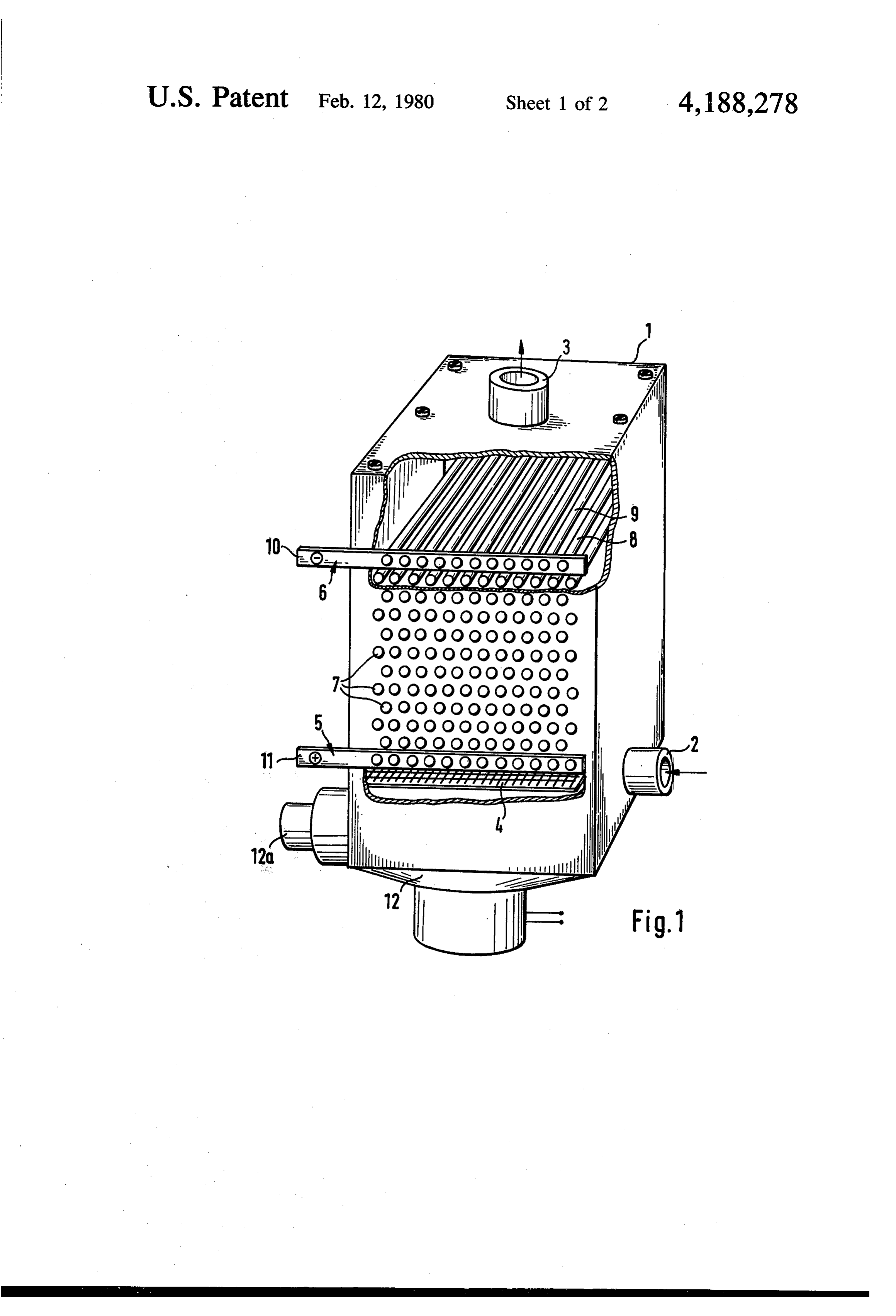
the housing 1. It flows through the sieve 4, around the
APPARATUS FOR DEGERMINATING FLUIDS main electrode 5, the auxiliary electrodes 7 and the second main electrode 6 and leaves the cell through the
This invention relates to an apparatus for degerminat outlet 3.
ing fluids by anodic oxidation employing a plurality of 5. The individual electrodes are combined to bundles electrodes and auxiliary electrodes through which the having liquid flows, and also a procedure for degerminating layers ofa certain bars or ratio of distance St to diameter d. The wires may be arranged as shifted or fluids by anodic oxidation. aligned or irregular bundles with the electrodes parallel In an apparatus for treating wastewater using an elec or cross-wise to each other.
trolytic cell described in DE-OS No. 2,324,795 (U.S. O In the further operational description a bundle of bars Pat. No. 3,893,900) two main electodes are arranged arranged parallel to each other and shifted from one parallel to the direction of flow. Auxiliary electrodes plane to the next is used. When the fluid flows through are provided in planes parallel with the main electrodes. this bundle of shifted bars in a vertical direction high Thus the liquid flows parallel to the electrodes. This accelerating and decelarating forces are acting on the causes dead zones between the electrode bars, and the 15 fluid along its path. In this way an intensive turbulence individual bar of a plane of electrodes acts similar to a plate electrode hit by tangential flow. In this way only is caused
The between the individual electrode layers.
intensity of this turbulence and thereby the mix a small part of the fluid reaches the boundary layers of ing rate of the fluid may be expressed by the coefficient the anodes and the germs are not fully affected.
An object of the present invention is to provide an 20 number Re is constant. pressure loss AP if the Reynolds of resistance J and the apparatus for degerminating fluids which as a high This value depends on the ratio Sa/d wherein Sais the degermination rate and a highly efficient anodic oxida distance of two bars of diameter d in one plane. It is tion.
independent
Another object of the invention is to provide a proce of two bars of of the ratio Si/d wherein S1 is the distance dure by which a high degermination rate and a highly 25 This diameter d from one plane to the next. results from the fact that the coefficient of resis efficient anodic oxidation may be accomplished.
According to this invention these and other objects tance ing is essentially determined by the amount of diverg the fluid:
can be accomplished by providing an apparatus wherein the electrodes are biased in such a way that the fluid flows through a region of varying potential. 30
The procedure to degerminate fluids by anodic oxida tion according to this invention can be accomplished by v-R-t letting the fluid flow through a region of varying poten T 8w2/2 tial and changing the direction of this varying potential. R, = w d
The principle, construction and operation of this. 35 y invention will be understood from the following de tailed description taken in conjunction with the accom Wherein AP is the pressure loss, w the velocity at the panying drawings in which smallest cross section, d the diameter of a bar, 6 the FIG. 1 is a perspective view of the cell for deger density and y the kinematic viscosity of the fluid. ni is minating fluids, partly showing the inside construction; 40 the number of layers counted in the direction of flow. FIG. 2 another embodiment of the main- and auxil- - The above mentioned equations are valid for numbers iary electrodes in a perspective view; n>10 only, otherwise the coefficient of resistance is FIG. 3 a top view of another embodiment of elec increased.
trodes arranged in a plane; and Owing to the high flow velocity at the smallest cross FIG. 4 a perspective view of another embodiment of 45 sections of the bundles and the resulting intense turbu the electrodes. lence zones behind each bar the cohesive powers of the According to FIG. 1 the apparatus consists of a hous gas bubbles on the surfaces of the bars are overcome in ing 1 made of insulating plastic having an inlet 2 on the their initial state by the inertial force of the fluid. lower part of the cell housing and an outlet 3 on its This leads to a removal of the gas and a continuous upper end for the degerminated fluid. 50 activation of the electrode surface. To make the shear Above the inlet 2 a sieve-shaped device 4 is arranged ing forces acting on the gas bubbles effective a thin to streamline the fluid. In the upper space of the housing boundary layer is necessary as the gas bubbles cover the 1 a plurality of bar-type electrodes 8, 9 is provided. surface in a very thin layer. This is accomplished by These electrodes may be secured to the cell wall by using bars of small diameter (d = 1 ... 3 mm) because of inserting them in holes provided therein and sealing 55 the short path of flow perpendicular to the axis of the with cement. bar.
The electrode bars are arranged perpendicular to the The intensive turbulence within the bundles also re direction of flow and parallel to each other, each group sults in a good interchange of fluid at the electrode of electrodes is aligned in a plane, the different planes boundary layers. By using a sufficient number n of elec are suitably spaced. Each row of the bar-type electrodes 60 trodes the greater part of the fluid is affected by the of one plane is shifted by half the distance of two bars boundary layer.
with respect to the bars of the following plane. In the apparatus described the aqueous solution and The lowermost row of bars is connected by an elec the germs contained in it are forced to pass the anodic trically conductive element 11 and the uppermost row or cathodic boundary layers thereby passing through a by a conductive element 10. An appropriate DC-poten 65 potential gradient of e.g. 0 to 11 Volts. As compared to tial is applied to the elements 10, 11. electrodes of any kind hit tangentially by the fluid a In operation of the cell the fluid, which is normally of higher chemical conversion ratio is attained by the de low conductivity, is introduced through the inlet 2 into scribed effects.
Page 5scan →
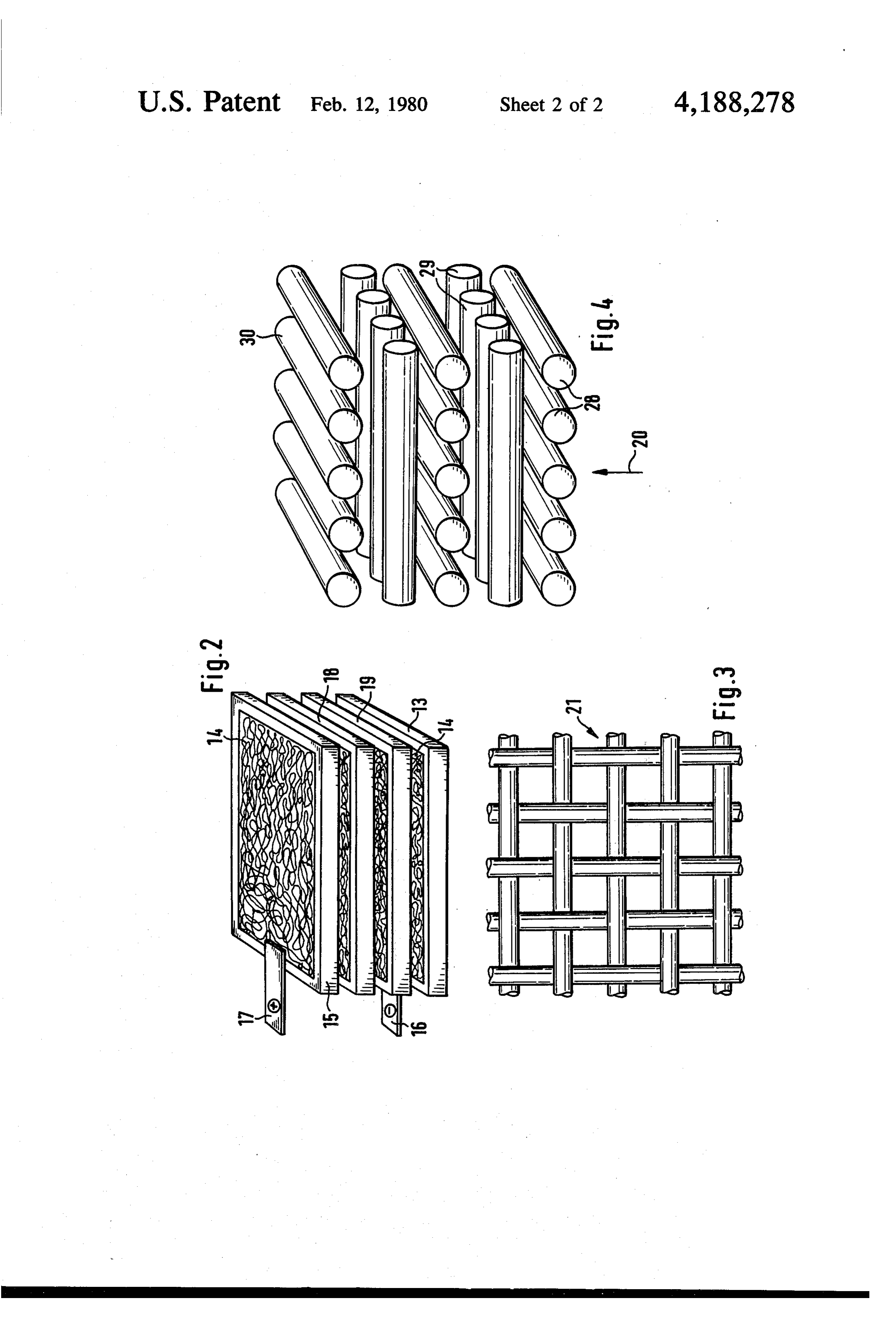
Basically it is possible to connect not only the two FIG. 2. The intermediate frames form the auxiliary main electrodes 5, 6 to the necessary potentials, but also electrodes.
to connect each row of bar-shaped electrodes to these In FIG. 4 another embodiment of an electrode ar potentials. The advantage of a bipolar circuit like this israngement is shown at an enlarged scale. The electrode that the overall voltage may be reduced. If for instance 5 bars 28, 29, 30 are arranged parallel to each other in one tapwater is to be treated, it is necessary to apply a volt plane, the bars of the following planes are arranged age of about 600 Volts as this fluid has a small conduc perpendicular to these thus forming a cross-shaped grid. tivity. This voltage may be reduced to 200 Volts by The electrode bars are secured to the cell walls and using three bipolar ranges. By applying a suitable subdi insulated according to the embodiment shown in FIG. vision it is even possible to use very small voltages of O 1. The bars 28, 30 of the outermost planes are connected approximately 2 or 3 Volts. In this way a degerminating by conductive elements to which the electrical potential apparatus according to the present invention may be is applied. Arrow 20 depicts the perpendicular direction built for countries with sufficient solar energy which is of flow through these cross-wise arranged bars. supplied by solar energy without any voltage transfor 15 What is claimed is:
mation. 1. An apparatus for treating fluids by anodic oxida A further improvement in removing the gas bubbles tion comprising may be attained by vibrating the electrodes with low an electrolytic cell, having an inlet and an outlet frequency. For this purpose a vibrator 12 is provided at through which said fluid flows, the bottom of the cell housing. The low frequency vi 20 a pair of main electrodes opposed to each other in the brations produced by this source are conducted to the electrolytic cell, electrodes by the cell walls. The vibration caused in this a voltage source connected to the main electrodes, way reduces the adhesive forces of the gas bubbles to a plurality of auxiliary electrodes disposed between the electrode surface thereby facilitating the removal by the main electrodes, the liquid flow. 25 each main electrode comprising a plurality of electri In spite of the good turbulence of the apparatus de cally connected bars which are arranged in a plane scribed so far it is possible that carbonate deposition and parallel to each other, occurs on the cathodic face of the electrode. To prevent each auxiliary electrode comprising electrically insu these depositions an ultrasonic source may be provided lated bars which are arranged in a plane and paral at the bottom of the cell housing. The vibration caused 30 lel to each other but whose bars are transversely by the ultrasonic source 12 prevents the mentioned shifted with respect to the bars of the adjacent deposition. If this deposition occurs though, the poten electrode, tial applied to the main electrodes may be reversed the main electrodes providing a region of varying periodically, for instance with a period of 15 minutes. potential between them through which the fluid This causes the deposit to split off thereby reactivating 35 flows, the entire electrode surface. the main electrodes located at the inlet and the outlet If the thin coating of an electrode bar is damaged in of the cell are substantially transverse to and cover operation, the described way of securing the electrode the entire cross-section of fluid flow and are pro bars to the cell wall facilitates the exchange of a bar, vided with openings between their bars to allow which is simply pushed out of its hole and replaced by 40 the passage of the fluid. inserting and sealing in a new bar. 2. An apparatus according to claim 1, in which a It may be added that the spacing of the bars affects vibrator provided on the economical operation of a cell as the ohmic resis frequency vibrations tothe the cell housing transfers low electrodes in order to re tance of the waste water causes dissipation. This loss move gas bubbles from the electrodes. can be reduced by making the spacing as small as possi 45 3. An apparatus according to claim 1, in which the ble. The minimum distance between the bars is deter mined by the medium to be treated and the pollution it direction of thereversed.potential applied to the main electrodes contains. Obviously it is necessary to make the spacing is periodically 4. An apparatus according to claim 2, in which a wide enough to allow the particles flowing with the streamlining element is provided between the inlet and fluid to pass through the bars without clogging the cell. 50 the
The spacing of the bars must therefore be wider than electrode zone.
the maximum diameter of the particles. FIG. 2 shows 5. An apparatus according to claim 3, in which an another embodiment of the main- and auxiliary elec ultrasonic source is provided at the cell housing which trodes. Each electrode consists of a frame 13 made of transfers vibrations to the electrodes. conductive material and of a wire grating 14 which is 55 6. An apparatus according to claim 5, in which the electrically connected to and supported by the frame. electrodes are secured to the wall of the cell housing. The frames may be inserted in the cell housing after 7. An apparatus for treating fluids by anodic oxida removing a wall, they are secured and spaced by insu tion comprising an electrolytic cell through which said lating spacers. The outermost frames 13, 15 are con fluids flow, nected to the electrical potential. In the embodiment 60 a pair of main electrodes opposed to each other in the shown in FIG. 2 the intermediate frames which form electrolytic cell, the auxiliary electrodes are not connected to the voltage a voltage source connected to the main electrodes, SOC. a plurality of auxiliary electrodes disposed between FIG. 3 shows at an enlarged scale a wire grating 21 the main electrodes, which may be used as an electrode plane. According to 65 the main electrodes on the inlet and the outlet side of this embodiment several of these frames consisting of the cell cover the entire cross-section of flow and twisted grid may be inserted in the cell housing, the are provided with openings to allow the passage of voltage is applied to the outermost frames as shown in the fluid, and 6 o direction of the potential applied to the main electrodes the main electrodes comprise a pressed wire grating is periodically reversed.
9. An apparatus according to claim 8, in which at which is electrically connected to and supported least one vibrator provided on the cell housing transfers by a frame. 5 low frequency vibrations to the electrodes in order to remove gas bubbles from the electrodes.
8. An apparatus according to claim 7, in which the k k k :k sk
Provenance
- Collection
- Patents citing this work
- Pages
- 6
- Method
- pdftotext (the PDF's own text layer) + pdftoppm 300dpi page scans
- Patent office record
- patents.google.com →
- Source
- Google Patents citing-documents table
- Assignee
- Institut Fur Biomedizinische Technik
- Published
- 1980-02-12
- Transcribed from
- patentimages.storage.googleapis.com →