

patent · US4204914A
Apparatus for desalinating water
27 May 1980
Text
Page 1scan →
United States Patent (19)
Diggs
54 apparatus for desalinating water
76) Inventor: Richard E. Diggs, 12A Rd.,
Carthage, Mo. 64836 (*) Notice: The portion of the term of this patent subsequent to Oct. 3, 1995, has been disclaimed.
Related U.S. Application Data
52 U.S. C. .................................... 202/176; 202/177;
58) Field of Search ..................... 203/DIG. 1, 10, 11,
1,661,473 3/1928 Goddard et al. .................... 126/271 1,969,839 8/1934 Goddard .............................. 126/271 2,183,956 12/1939 Campbell et al. . ... 165/110 2,803,591 8/1957 Coanda et al. ... 203/DIG. 1 2,965,819 12/1960 Rosenbaum .................... 203/86 UX 2,975,107 3/1961 Friedman ...... ... 203/DIG. 1 3,168,451 2/1965 Gorand .................................... 203/2
3,249,519 5/1966 Cabbage et al. ......................... 203/2 3,958,553 5/1976 Brantley ............................... 126/271 Primary Examiner-Wilbur L. Bascomb, Jr.
Attorney, Agent, or Firm-Shoemaker and Mattare, Ltd.
An apparatus and method for removing contaminants from water having solid contaminants dissolved therein. Contaminated water flows across a grid and into a stor age tank. The grid utilizes solar energy to heat that water to a predetermined temperature. A heat transfer structure which is dome-shaped and receives water from the storage tank and a preheater means utilizing solar energy heats the water to a further predetermined temperature. An evaporator means receives the heated water and exposes it to a vacuum condition so that the temperature of the water is above the saturation temper ature. The water is thus vaporized, and solid contami nants dissolved therein are separated therefrom. The solids are deposited on a plurality of moving belts and are then moved into a solids removal system. The solids removal system comprises a plurality of trap door pairs upon which the solids are deposited and which are sequentially opened so that the vacuum conditions ex isting in the evaporator are not disturbed. Vapor trans ferring means removes the water vapor from the evapo rator and transfers it to the heat transfer structure wherein it is condensed to form distillate which is free of solid contaminants. Distillate removal means then removes the distillate from the heat transfer structure to collection or usage means.
8 Claims, 21 Drawing Figures
Drawings
Page 2drawing sheetscan →
Page 3drawing sheetscan →
Page 4drawing sheetscan →
Page 5drawing sheetscan →
Page 6drawing sheetscan →
Page 7drawing sheetscan →
Page 8drawing sheetscan →
Page 9drawing sheetscan →
Page 10scan →
triple point). Therefore, the power required to raise
APPARATUS FOR DESA LINATING WATER water to the saturation temperature is decreased as the pressure of the system is decreased. This fact is utilized
This is a division of application Ser. No. 625,850, filed by some known distillation systems. However, due to Oct. 28, 1975, U.S. Pat. No. 4,118,283. the nature of the elements used by these devices to BACKGROUND OF THE INVENTION produce the reduced pressure environment, only a small amount of liquid can be treated at one time. Further
The present invention relates to desalination, and, more, these devices do not produce a continuous flow more particularly, to an apparatus and a method utiliz through the distillation apparatus. Thus, the saline ing solar energy in the desalination process. 10 water is flooded into a chamber, the chamber is then Distillation devices are used to purify volatile sub closed off, a reduced pressure condition is then pro stances, and have found application in the chemical and duced in the chamber, and then heat is input into the petroleum industries. Recently, such devices have been saline water to vaporize it. Therefore, inflow into the used in desalination processes wherein salts are precipi distillation apparatus is interrupted while the vaporiza tated out of saline water to produce pure water. Re 15 tion process is occurring, and the production of pure cently, there has been an interest in applying distillation water of the system is therefore limited. Such a system processes to desalinating large quantities of water. This is therefore not suitable for desalinating extremely large interest has been sharpened due to droughts in vast land quantities of water. Furthermore, due to the nature of areas which are, however, located near great bodies of the pressure reduction step, the vaporization step is salt water. An apparatus and a process which efficiently 20 carried out in a chamber which communicates with the desalinates large amounts of water could find wide condensation chamber in such a way that the distillate is applications in such drought ridden areas, as well as in exposed to the solid residue, therefore producing the densely populated areas which, at present, appear to above-discussed possibility of recontaminating the dis have adequate water supplies. tillate and thereby reducing the effectiveness of these Most known distillation devices suffer a common 25 systems.
drawback of inefficiency, and hence are not suitable for In the device embodying the present invention, water use in such large scale applications. This inefficiency is heated utilizing solar energy and then transferred to a results in either low outputs of pure water or in ex vacuum chamber where it is vaporized and the water tremely high power requirements. Therefore, known vapor separated from the solid residue in a continuous devices are either incapable of supplying the quantity of 30 flow process. The water vapor is then transferred to a pure water reqired, or require such high power inputs separate condensing chamber where it is condensed to as to result in unacceptable environmental pollution. form pure distilled water. Some known devices have somewhat remedied the SUMMARY OF THE INVENTION inefficiency of the distillation process by utilizing solar energy as a means of augmenting the power input. The 35 The saturation temperature of the contaminated solar energy is commonly utilized during the vaporiza water being vaporized by the distillation apparatus em tion step in the distillation process. However, these bodying the present invention is very low as compared devices vaporize the water at atmospheric conditions, to the saturation temperature thereof at atmospheric and the heat input required to vaporize water at atmo pressure. Furthermore, condensation of the water spheric conditions is quite large. Therefore, the output 40 vapor occurs at, or near, atmospheric pressure and of such devices is quite limited. These devices must be therefore the water vapor is at, or below, the saturation either unreasonably large or require large solar energy temperature of water at atmospheric pressure. There transfer devices. Thus, there are known devices which fore, solar energy can be utilized to supply sufficient utilize solar energy in the vaporization step which em heat input to raise the temperature of large quantities of ploy solar grids covering several acres of area, and large 45 contaminated water above the saturation temperature amounts of land area are consumed by the solar heating required in the vaporization process occurring in the means itself. evaporation chamber. The water vapor is then trans A further drawback of known devices results because ferred to a condensation chamber wherein the pressure the vaporization and condensation steps are carried out is at, or near, atmospheric pressure, hence less heat has in a common chamber. Thus, the distillate often be 50 to be removed from the water vapor to condense it, and comes recontaminated due to its proximity with the the condensation step occurs quite rapidly. Once vapor solid residue originally removed therefrom. It is for this ized, the water vapor and the solids dissolved therein reason that many of the known distillation devices pro are separated, and the vapor is condensed in a separate vide recirculation systems for recycling the distillate in chamber, thereby substantially reducing the possibility an attempt to assure total removal of substantially all of 55 of recontamination of the distillate with solids which the solid contimanants. However, because of the above have been removed from the contaminated water by the mentioned proximity of the distillate and the solid resi distillation process.
due, known processes are somewhat self-defeating. Be Hence, the apparatus and method embodying the cause of the recycling, procedure, the net output of present invention is capable of efficiently desalinating known devices is further limited and total separation, 60 extremely large quantities of water which have been along with efficiency, are goals which, in many ways, contaminated by solid particles being dissolved therein. are exclusive of each other. The device can therefore utilize solar power to distill As is well known, as the pressure of a system is de such contaminated water with an efficiency which is creased, the saturation temperature of water in that quite high as compared to known devices. system also decreases. For example, at atmospheric 65 The apparatus embodying the present invention com pressure, the saturation temperature of water is 212 F., prises a pump means located in a large body of water at 10 psia it is 193.21". F., at 5 psia it is 162.24 F., at 1 which has been contaminated by solid contaminants psia it is 101.74 F., and at 0.0886 psia it is 32.02 F. (the dissolved therein, such as a river or a salt sea. The pump 11 transfers water from the body of water to a solar heat Because of the non-polluting and efficient manner in ing grid across which the contaminated water flows. which the apparatus operates, it can safely be utilized in The solar heating grid transfers solar energy to the highly populated areas, and is therefore effective to water flowing thereacross in order to raise the tempera provide such areas with a source of pure water. ture of that water to a predetermined level. A second OBJECTS OF THE INVENTION pump means transfers the water from the solar grid to a storage means when that water has attained a pre Accordingly, it is the main object of the present in scribed temperature. Recirculation means are also pro vention to separate large quantities of pure water from vided to maintain the water on the solar heating grid a body of water which has been contaminated by solid until the prescribed water temperature has been at O contaminants dissolved therein.
tained. Another pump means is located in the storage It is a further object of the present invention to pro means to transfer the water stored therein into the evap duce total separation of the contaminated water to a oration system of the apparatus. condition of either pure water or solid residue. The evaporation system comprises a dome structure It is yet another object of the present invention to having a piping system therein through which the water 15 desalinate large quantities of water in an efficient and is circulated from the storage means. The dome struc economical manner.
ture also serves as a condensation means and therefore It is still a further object of the present invention to exposes the water being circulated through the piping desalinate water in such a manner that large quantities system therein to the condensing vapors which preheat of solid residue can be easily salvaged. the water in the pipes of the dome structure, as well as 20 It is still another object of the present invention to removes heat from the water vapor during the conden desalinate large quantities of water with an apparatus sation step. which produces a minimum of environmental pollution. From the dome structure, the water is transferred to It is yet a further object of the present invention to a heater means located adjacent the dome structure. In desalinate large quantities of water with an apparatus the heater means, solar energy is focused on the water 25 having low power requirements.
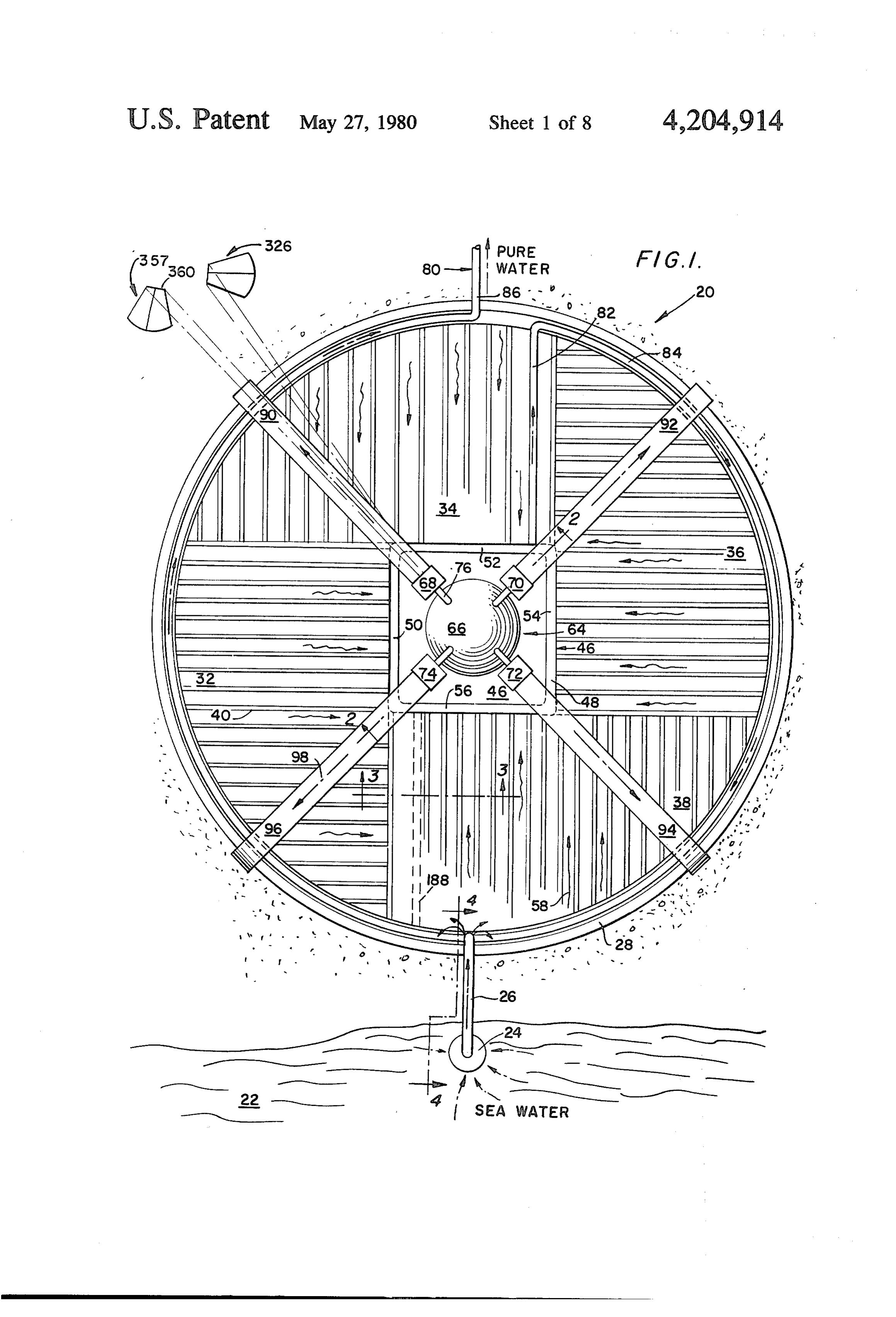
to raise it to a predetermined temperature. In the heater BRIEF DESCRIPTION OF THE DRAWINGS means, auxiliary heat input means can be used to com pensate for reduced sunlight on cloudy days, or to aug FIG. 1 shows a plan view of the apparatus embody ment the solar energy input and thereby further increase ing the present invention located adjacent a body of the output of the apparatus embodying the present in 30 contaminated water;
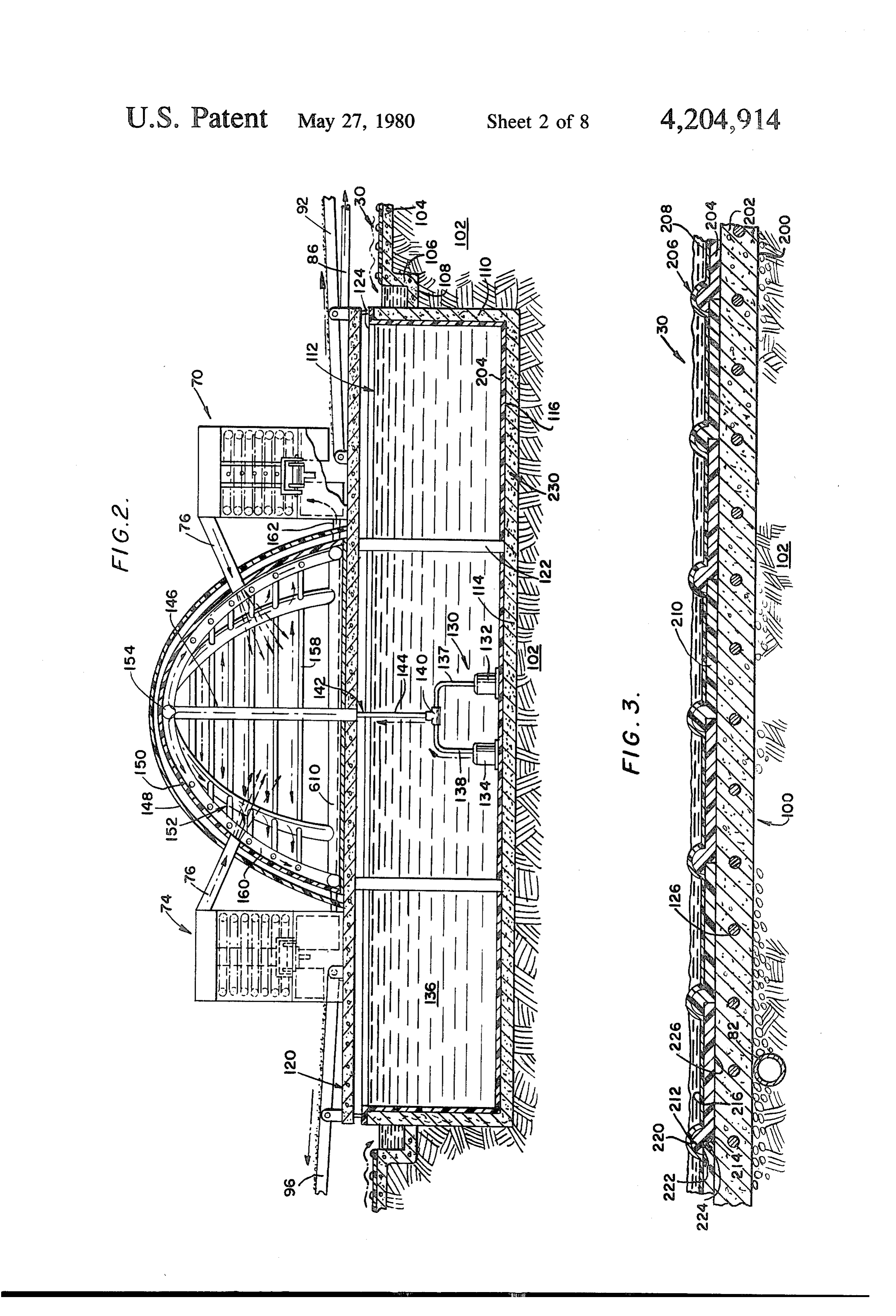
vention. FIG. 2 is a vertical, sectional view taken along line A vaporizing chamber is positioned adjacent the 2-2 of FIG. 1;
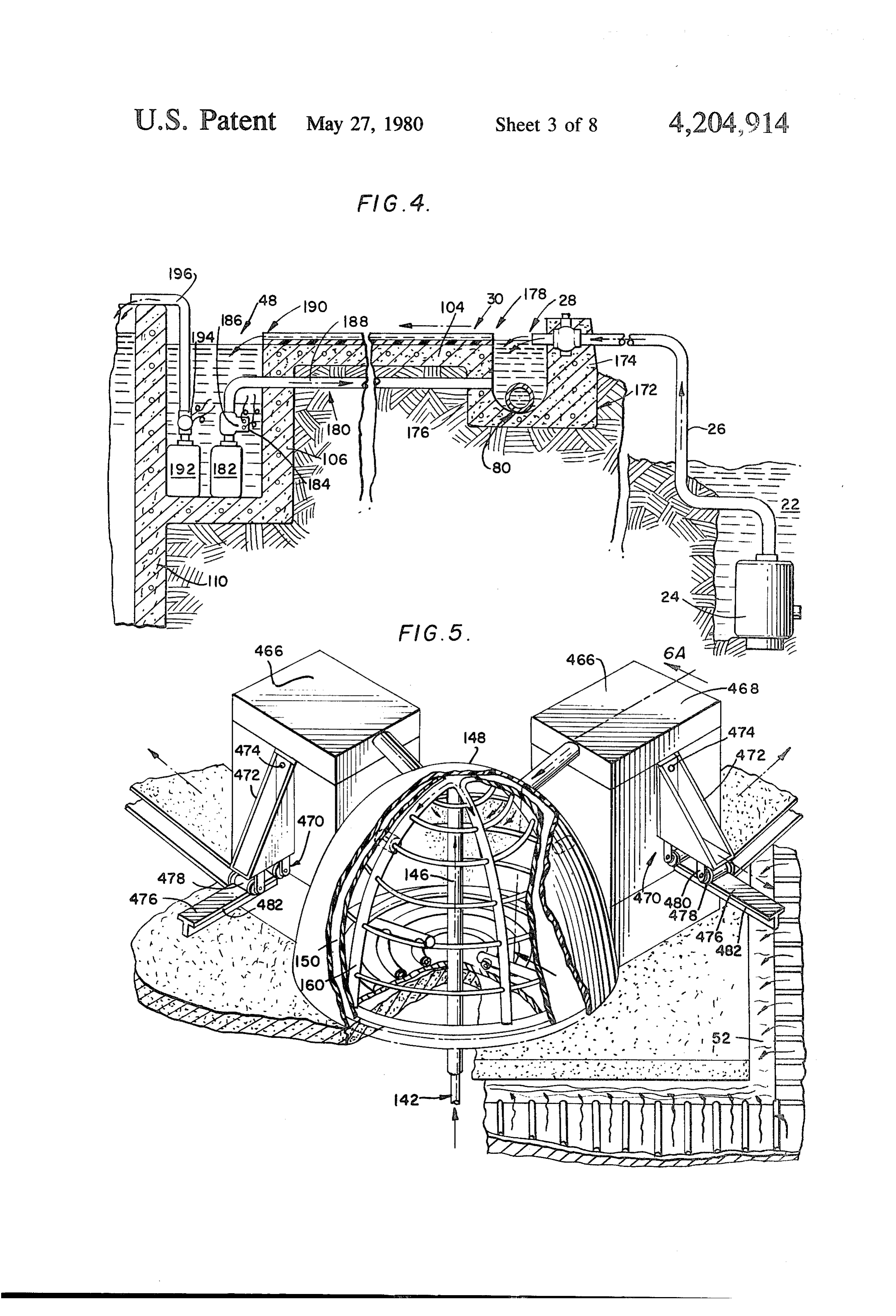
above-mentioned heater, and the heated water is trans FIG. 3 shows a detailed section of the solar heating ferred thereto. Vacuum pumps are associated with the grid utilized in the apparatus of the present invention vaporizing chamber to reduce the pressure in the vapor 35 and is taken along line 3-3 in FIG. 1; izing chamber to a level so that the temperature of the FIG. 4 shows a recirculation system used in the appa incoming water is above the saturation temperature of ratus of the present invention and is taken along line that water. The water is sprayed onto moving belts in 4-4 in FIG. 1;
the vaporization chamber and vaporizes. FIG. 5 shows a perspective, cut-away view of the The water vapor is removed from the vaporization 40 dome structure utilized in the apparatus of the present chamber by the vacuum pumps, and the solid residue, invention;
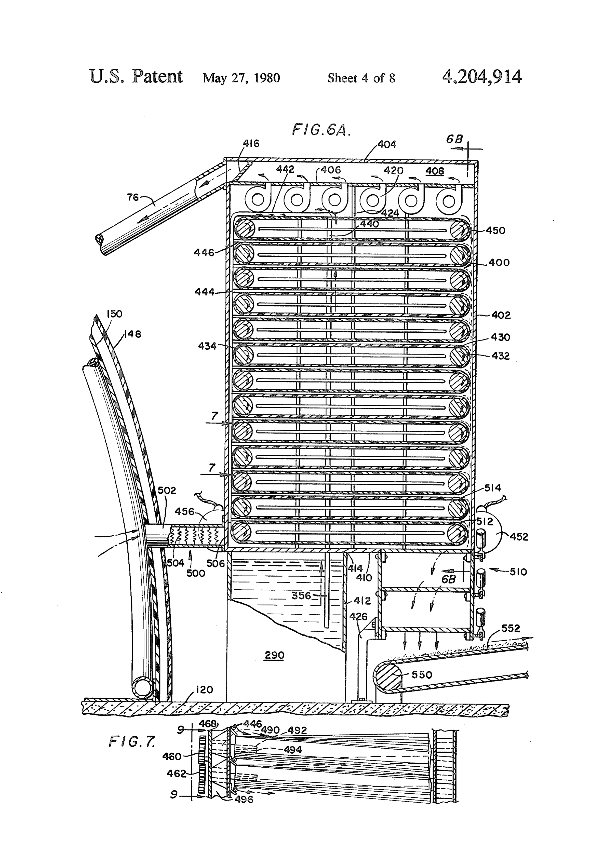
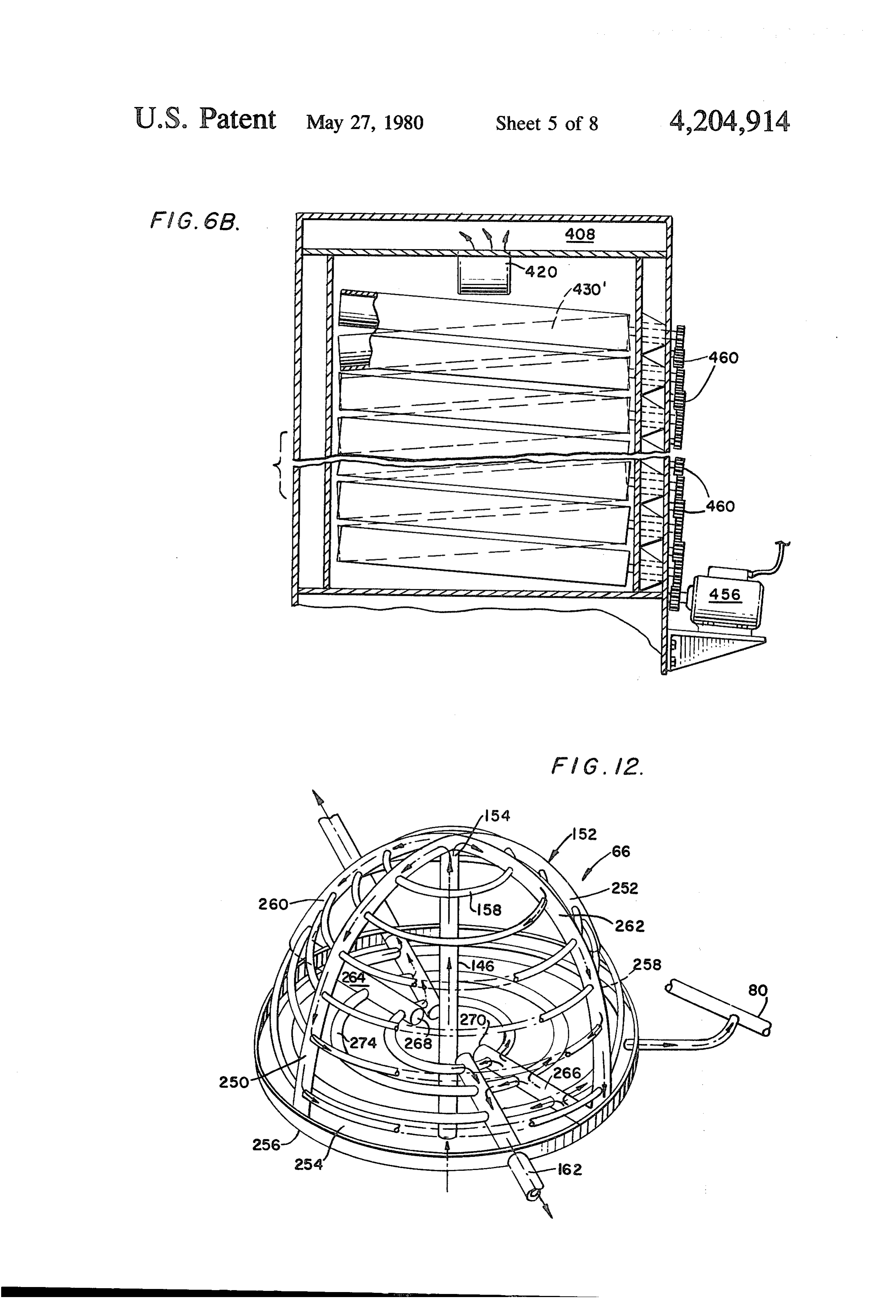
and the sludge, remains on the belts in the vaporization FIGS. 6a and 6b show details of the vaporization chamber. The residue and sludge is removed from the apparatus used in the present invention and are taken belts by means such as doctor blades, and is transferred along line 6a-6a in FIG. 5, and 6b-6b in FIG. 6a, to a removal system and is removed from the vaporiza 45 respectively;
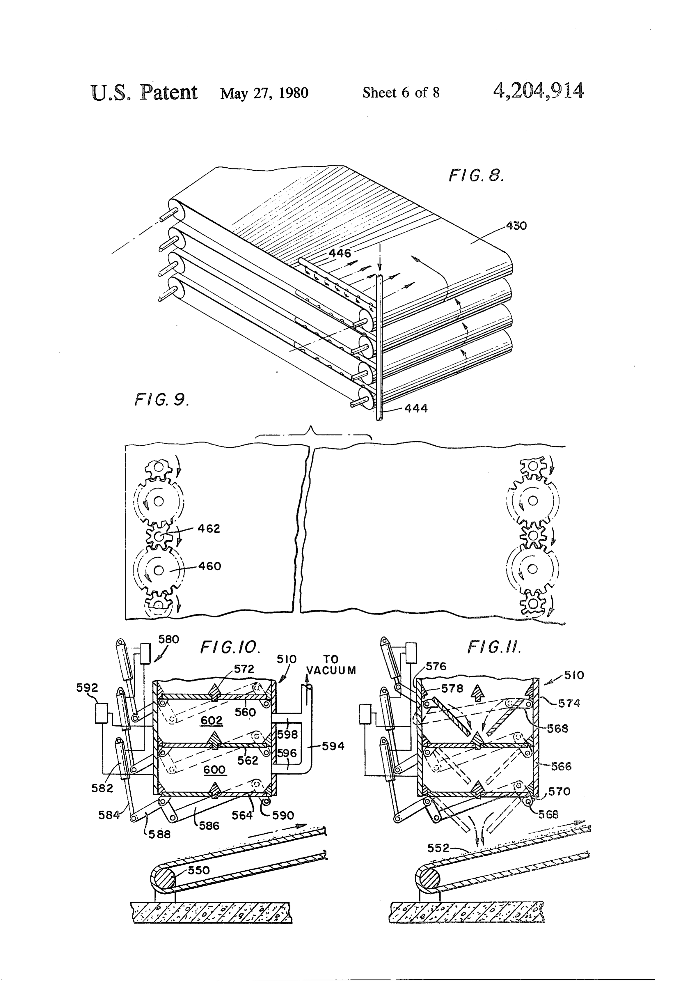
tion chamber. FIG. 7 is a taken along line 7-7 of FIG. 6a and The water vapor is transferred to the aforementioned shows details of the belt system used in the vaporization dome wherein it is exposed to the pipes containing con apparatus;
taminated water. As the dome is at, or near, atmo FIG. 8 is a perspective view of the belts used in the spheric pressure, the water vapor rapidly condenses to 50 system of FIG. 6a water and can be removed as pure water. FIg. 9 shows details of a drive system used to drive The system is so efficient that it is virtually self-sup the belts shown in FIGS. 7 and 8 and is taken along line porting during hot, sunny days and can sustain opera 9-9 of FIG. 7;
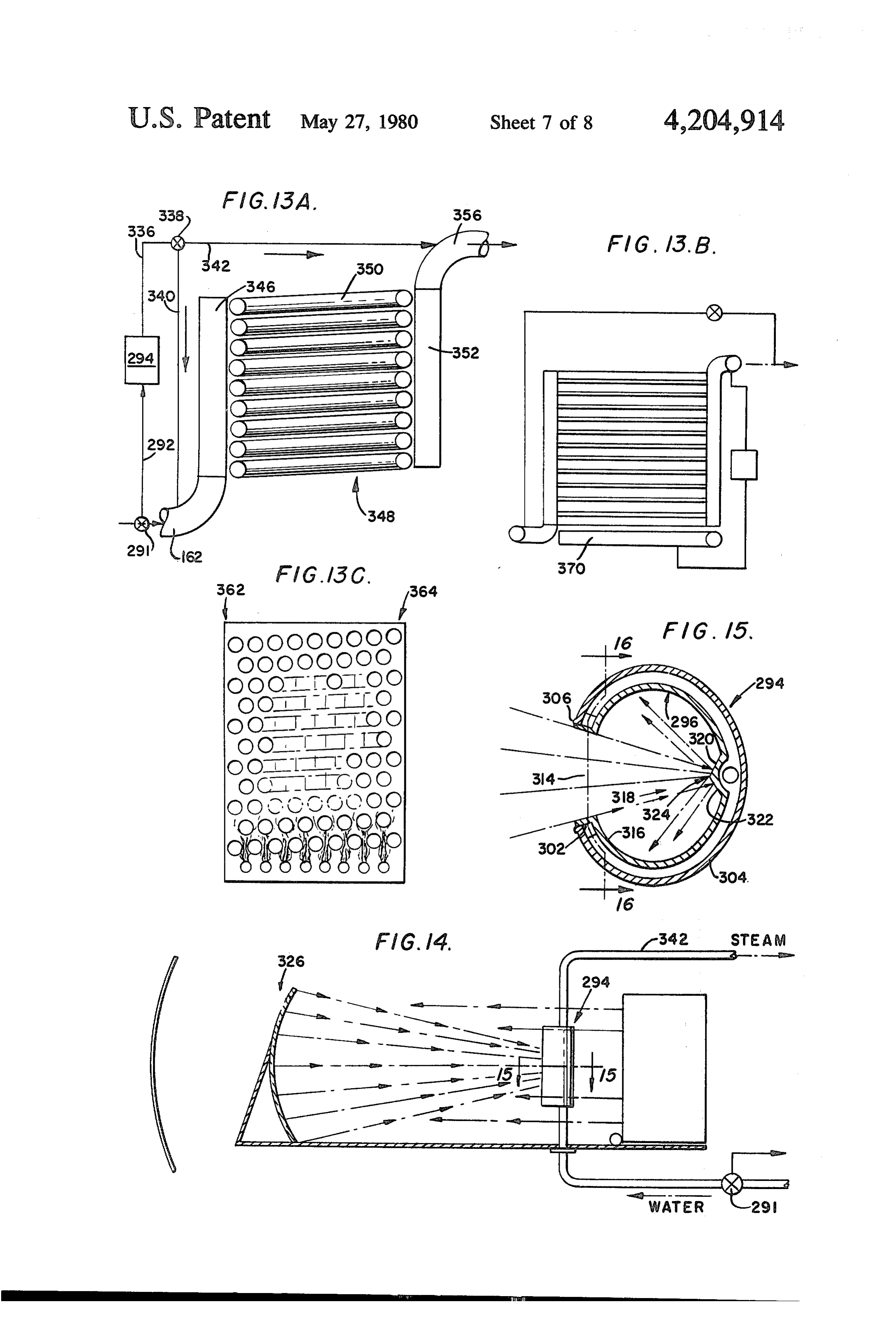
tion for several days without additional sunlight before FIGS. 10 and 11 show details of a system used to extensive auxiliary heating is required. Therefore, the 55 remove solid residue from the vaporization apparatus apparatus and method embodying the present invention shown in FIGS. 6a and 6b can be used for desalting extremely large bodies of FIG. 12 shows details of the heating dome used in the water, such as rivers, in an efficient manner which does apparatus of the present invention; not itself pollute the environment. FIGS. 13a-13a show details of a heater unit utilizing Futhermore, the apparatus and method embodying 60 solar energy to heat the contaminated water prior to the present invention produces a total reduction of con indroduction thereof into the vaporization chamber of taminated water to a condition of either fresh water or the apparatus of the present invention; a solid contaminant. The device can therefore be used FIG. 14 shows details of a boiler system which is extensively in re-cycling water for pollution control utilized with the FIG. 13 heater;
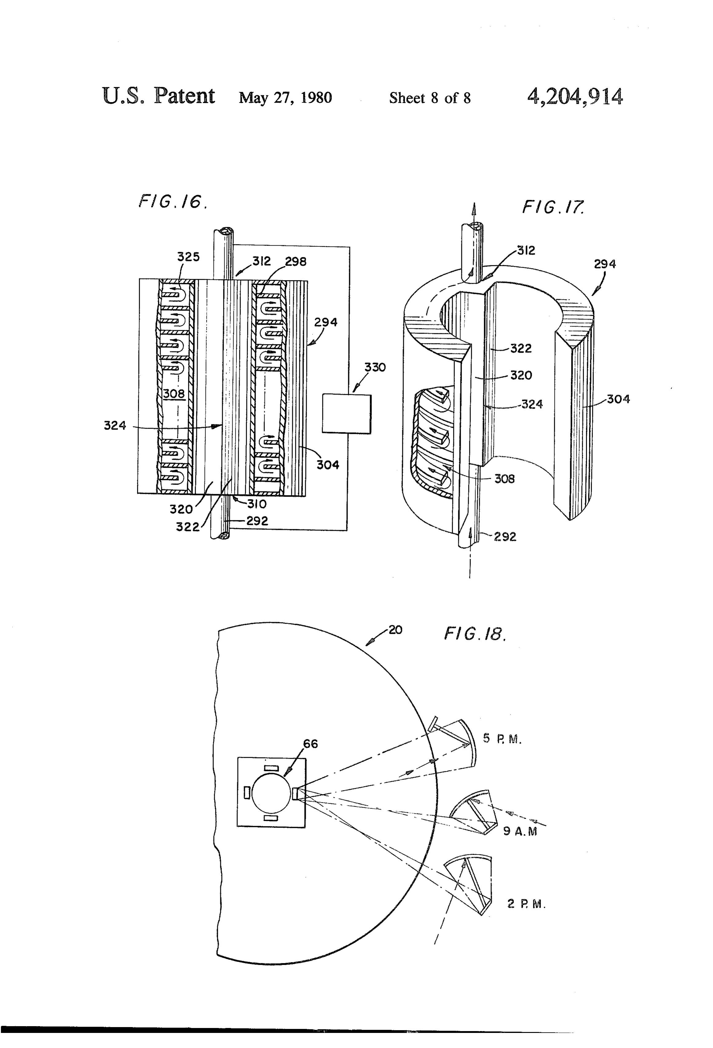
purposes, allowing the removal of valuable compounds, 65 FIG. 15 is a schematic diagram of the system used to chemicals, and elements from polluted water while at transfer solar energy to the water in the FIG. 13 heater; the same time providing water that can be recycled FIG. 16 shows further details of the solar transfer through the plant again and again. means shown in FIG. 15;
Page 12scan →
FIG. 17 is a perspective view of the boiler shown in the main storage tank 112. As shown in FIG. 2, a main F.G. 14; and platform 120 forms a mounting base and is supported by FIG. 18 is an overall schematic of the placement of main support columns 122 and end support columns 124 solar transfer means used in conjunction with the FIG. mounted on the upper edge of the concrete wall 110. 13 heater. 5 The main platform 120 is formed of reinforced concrete
Description of the preferred
having reinforcing ties 126therein and supports thereon
Embodiment
the dome 66 and the vaporizing units, as well as the residue removal elements, such as conveyor belts 92 and
Shown in FIG. 1 is a distillation apparatus 20 located 96. Located in tank 112 is a second pumping means 130 adjacent a body of contaminated water, such as a river 10 comprising a main pump 132 and an auxiliary pump 134 or sea 22, which has solid contaminants dissolved for removing water 136 which has been stored in the therein. A first pump 24 is located in the sea 22 and main storage tank 112. The two pumps feed into con removes water therefrom. The removed water is trans duits 137 and 138 which are connected by a T-connec ferred through a conduit 26 and into a header 28 which tion 140 to a common riser conduit 142. The common surrounds the apparatus 20 along the outer perimeter 15 riser conduit 142 is comprised of a first section 144 and thereof. From the header 28, the contaminated water a second section 146 which passes through the main flows across a solar heating grid 30 comprised of four platform 120 upwardly into dome 66. The dome 66 is sections 32-38. Each grid section comprises a plurality comprised of an outer wall 148 and an inner wall 150 of parallel flow channels 40. As shown in FIG. 1, the and a plurality of preheater pipes 152 located inside the flow channels of each grid section are parallel with each 20 dome adjacent inner wall 150 and connected to outlet other and are perpendicularly disposed to the flow end 154 of section 146 of the riser conduit. As will be channels of the adjacent grid sections for inducing tur later discussed, a plurality of horizontal connecting bulence in the water flowing across the solar heating conduits 158 interconnect vertical sections 160 of the grid to thereby increase the heat transfer from the grid preheater pipes 152. The conduits 76 and 162 connect to the water flowing thereacross. Centrally disposed of 25 the vaporizer units to the dome 66. Either, or both, of the distillation apparatus 20 is a storage means 46 com the pumps 132 and 134 can be used to withdraw water prised of a moat or trough 48 which connects to the from the storage tank 112 and transfer it to the pre inner perimeter of the solar heating grid 30 at sections heater pipes 152. The pumps 132 and 134, like pump 24, 52-56. Flow arrows 58 indicate the direction of flow should be durable, and resistant to corrosion by the across the solar heating grid 30 into the trough sections 30 contaminants dissolved in the contaminated water being of trough 48. Located above storage means 46 is a heat desalinated by the distillation apparatus 20. transfer structure 64 comprised of a dome 66 and four As shown in FIG. 4, water removed from the sea 22 vaporizer units 68-74 connected to the dome 66 by by the pump 24 is transferred through conduit 26 into a conduits 76. A pure water transfer duct 80 comprises a pipe coupling which distributes the water from conduit first section 32 connected to the dome 66 and traversing 35 26 into header 28 which is comprised of a footing sec across the solar heating grid section 34 into header 28 tion 172 and two wall sections 174 and 176, which con and a circular second section 84, which is located in the nects to the horizontal portion 104 of the concrete base header 28 and traverses the outer perimeter of the appa 100. As shown in FIG. 4, wall 176 forms with horizon ratus 20 in that header to connect with a third section tal section 104 a spillover 178 over which the water 86. The third section 86 is connected to any suitable from trough 28 flows onto the solar heating grid 30. The pure water usage or storage device. By locating second solar heating grid transfers solar energy to the water section 84 in the header 28, the hot pure water is utilized flowing thereacross to raise that water to a predeter to transfer heat to the incoming contaminated water and mined temperature. A recirculation system 180 com thereby raise the temperature of that contaminated prising recirculation pump 182 having an intake 184 and water to make effective use of the energy input into 45 a temperature control 186 and a return conduit 188 apparatus 20. A plurality of conveyor belts 90-96 are removes water from trough 48 and returns it to header connected to the vaporizer units and extend radially 28 for further heating thereof. As shown in FIG. 4, the outward therefrom to the outer perimeter of the distilla vertical wall 106 forms with horizontal section 104 a tion apparatus 20 and transfer the solids produced in the spillway 190 over which water from solar heating grid distillation process to convenient storage and/or usage 50 130 flows into trough 48. When the water in trough 48 devices. Arrows 98 indicate the direction of movement reaches the proper temperature, the recirculation pump of the conveyor belts. 182 is shut down and transfer pump 192 comprising FIG. 2 is an elevation view on section 2-2 of the temperature control unit 194 and transfer conduit 196 is distillation apparatus 20. As shown in FIGS. 2 and 3, the started to transfer water from the trough 48 into main solar heating grid 30 is mounted on a concrete base 100, 55 storage tank 112 over wall 110. The trough 48 is sized to which, in turn, is mounted on a dirt foundation 102 contain approximately a one day supply of water so that which supports the entire apparatus 20. The concrete the apparatus 20 can operate uninterrupted for 4 full base 100 comprises a horizontal section 104 which at days without withdrawing water from the sea 22. A taches at one end to header 28 and at the other end to 60 plurality of pumps 182 and 192 are located in the trough vertical section 106 to form an outer wall of the trough at various points therein, and, like the other pumps in 48. Another horizontal section 108 forms the bottom the device, are durable and resistant to corrosion from wall of the trough 48 and connects to the outer surface the solid contaminants contained in the water being of wall 110 of a main storage tank 112 having a base 114 desalinated by the system. The pumps 182 and 192, like supported in the dirt foundation 102. The main storage pumps 132 and 134, are submersible and hence any heat tank 112 is large enough to contain enough water to 65 generated thereby is utilized to raise the temperature of supply the apparatus with water for approximately the water in the storage system. For clarity's sake, the three days without interruption. A plastic material cov outer edge of the main platform 120 and the corre ering 116 covers the solar heating grid and the inside of sponding support column 124 is not shown in FIG. 4;
Page 13scan →
however, the main platform, as shown in FIG. 2, covers heating grid 30, the base 114 of the storage tank 112 and the entire top surface of the main storage tank 112. the wall 110 of that storage tank. Shown in FIG. 3 is a detail of the solar heating grid As shown in FIG. 1, the preferred embodiment com 30 taken along section 3-3 of FIG. 1. As shown in prises a square storage tank, however, a circular storage FIGS. 1 and 4, the solar heating grid 30 is at a higher tank may also be used.
elevation than the bottom of the main storage tank 112 As shown in FIGS. 2, 5 and 12, dome 66 forms a heat and surrounds the outer periphery of that tank so that transfer structure wherein water from main storage tank the main storage tank is centrally located within the 112 is preheated and water vapor from vaporizer units solar heating grid and the outer perimeter thereof is 70 through 76 is condensed. As shown in FIGS. 1 and 2, circular. 10 the dome 66 is located centrally of the distillation appa FIG.3 best shows the details of the solar heating grid ratus 20 and supported on the main platform 120. 30. As shown, the solar heating grid comprises a gravel The arrangement of the preheater pipes 152 is best sub-base 200 overlying the dirt foundation 102, and shown in FIG. 12, wherein water from the main storage upon which a layer of reinforced concrete 202 is over tank is pumped through the section 146 of the riser pipe laid. In the preferred embodiment, the concrete layer 15 to top end 154. Two deadend pipes 250 and 252 are 202 is approximately 4 inches thick. The concrete is connected to the top end 154 and are mounted on the covered with an extruded, rigid, insulation board 204. deck 254 of the dome. The deadend pipes comprise In the preferred embodiment, the insulation board is blank ends 256 and 258 mounted on diametrically oppo either polystyrene or polyurethane. A plurality of pro 20 site sides of the deck 254. The piping system further trusions 206 are formed on the insulation board to define comprises pipes 260 and 262 having horizontal legs 264 the flow channels 40, as shown in FIG.1. The insulation site and 266, respectively, mounted on diametrically oppo board is covered with a coating 208, which, in the pre sides of the riser section 146 in the deck 254. Blank ferred embodiment, is Teflon. This coating corresponds ends 268 and 270 of the pipes 260 and 262 are also lo cated in the deck 254. As shown in FIG. 12, the pipes to the covering like shown in FIG.2, and, in fact, may 25 250, be the same coating. The insulation board comprises a rants.252, 260 and 262 divide the deck 254 into quad plurality of sections, such as section 210, which com prises longitudinai edges 212 and 214 and a top surface 158Asconnect shown in FIG. 12, a plurality of connecting pipes 216 which may have a protrusion thereon which is 260 and 262,the deadend pipes 250 and 252 to the pipes and a plurality of deck pipes 274 connect located intermediate the longitudinal edges 212 and 214. 30 the horizontal legs 264 and 266 of the pipes 260 and 262 A protrusion 220 is positioned on the top surface 210 to project outwardly from longitudinal edge 212 so that to outlet conduits 162. As shown in FIG. 2, the outlet conduits 162 are connected to the vaporizer units. The the base 222 of the protrusion 200 extends outwardly pipes 250,252,260 from ledge 212 to form with longitudinal edge 212 a to hold the dome and 262 serve as structural members upright and to retain water vapor shoulder 224. A longitudinal edge 214 is received in the 35 transferred from the condensing shoulder 224 with protrusion 220 overlapping the longi densed into water. Furthermore, theunits until it is con pipes provide cool tudinal edge 214 to interconnect the plurality of sections ing surfaces upon which the water vapor condenses and 210 together to form the quadrants of the solar heating transfers the heat of condensation to the water being grid 30. Glue, or other suitable fastening means, can be used to fix the plurality of sections together, and to the transferred from the main tank 112 to preheat that wa ter. Therefore, water transferred into the dome from the concrete base along the lower surface 226 of each of the main storage tank flows through all of the structural sections 210.
In the preferred embodiment, the coating 208 is a members. The water flows downward through deadend members 250 and 252, across connecting pipes 158 into dead black Teflon. Teflon is used for its high heat resis pipes 260 and 262, and through deck pipes 274 into tance and for its non-adhesion characteristics so that 45 conduits 162. The water therefore flows on a circuitous nothing will stick to it, including any possible salt de path through the entire dome structure 66. The circu posits. Even though some of the water molecules pass itous path maximizes the heat transfer characteristics of ing over the solar heating grid will evaporate, the per centage of such evaporation will be so small that solid the heat transfer structure. Furthermore, the deadend members induce turbulent flow within the pipes to fur percipitation will be negligible, and the amount of water 50 ther increase the heat transfer between the condensing lost in the evaporation will also be negligible. vapors and the waterflowing in the pipes. Furthermore, In the preferred embodiment, the flow velocity of the the pipes are manufactured of a thermally conductive water crossing the solar heating grid will be adjusted so material to further promote the aforementioned heat that the temperature of that water will be between 175' transfer.
F. and 195 F. As discussed above, the flow velocity is 55 somewhat controlled by the temperature controls 186 290,From the dome 66, the water flows into final heaters one of which is associated with each of the vapor and 194 of the pumps positioned in the trough 48. izer units and is located adjacent the dome and the Another embodiment of the solar heating grid 30 will vaporizer unit. As shown in F.G. 13a, a valve 291 is comprise a plurality of sections 210, each comprising positioned in conduit 162 and connects to a conduit 292 only a single protrusion 220. This embodiment is the leading to a boiler 294. The boiler 294 is best shown in preferred embodiment, and is the one shown in FIG. 3. FIGS. 14 through 17, and comprises two pieces. A first As shown in FIG. 2, the main storage tank 112 will piece is shown in FIG. 14, and comprises an aluminum also be lined with insulation board similar to insulation casting 296 with vanes 298 on the outer periphery board 204. Of course, the storage tank lining will not thereof. As shown in FIG. 17, these vanes stop short of need protrusions similar to protrusions 206. Further 65 the ends of the boiler alternately on each side at points more, the insulation board in the storage tank will also 302, shown in FIG. 15. A segment of heavy aluminum be placed over a concrete base 230 which is similar to pipe 304 is fitted over the outer surface of the aluminum the concrete base 100 forming the base of the solar casting and welded at point 306, and also around the top 14 and bottom of the boiler. Thus, a closed vessel with into contact with surrounding pipes. Therefore, a major alternate end fins is produced. The vessel forces the portion of the solar energy is utilized. The pipes are also water to run first right and then left, as shown in FIG. staggered in vertical columns to maximize the heat 16, as it moves up through the heat exchange chamber transfer from an auxiliary heater 370 shown in FIG.13b. 308 of the boiler from conduit 292 into inlet 310, and out The auxiliary heater can, like the other pumps and through discharge outlet 312. The inlet and outlet are motors, be either electric or fuel powered and is used to each tapped and threaded. augment the heat transfer from the solar reflectors on As shown in FIG. 15, the transverse cross-section of cloudy days, or after dark.
the boiler is C-shaped having an opening 314 and an The vertical and horizontal space in between the inner surface 316 which comprises a peaked section 318. O pipes 350 is arranged to produce a minimum of shadow The peaked section 318 comprises two oppositely slop ing as well as a maximum area to receive heat from the ing planar surfaces 320 and 322 and an apex 324 formed auxiliary heaters. Therefore, the combination of the by the inner section of the two planar surfaces. The boiler 294 and the solar energy transfer heater 348 is a peaked section runs longitudinally of the boiler and unique design which obtains a very high efficiency from therefore serves as a ray dispersal means for dispersing 15 three different heat sources, separately or simulta solar rays entering the enclosure through opening 314. neously. First, when the sun is not shining, extra heat is This feature will be discussed in greater detail below. added by the auxiliary heater 370. The heat pipes 350 The arrow 325 shows the path followed by the water as are staggered so that direct impingement is obtained on it flows through the heat exchange chamber 308. every pipe as the heat rises through the transfer heater As shown in FIG. 1, in the preferred embodiment 20 348. Second, the pipes are arranged so that the light there are four vaporizer units. Hence, there will be four from the solar reflectors penetrates 50% of the way in final heaters. The boilers associated with each of the from each side with equal surface exposure on each vaporizer units are oriented to receive solar radiation tube. Third, the inlet design of the entrant header 346 is reflected by the first solar reflectors 326. The casting arranged and connected to the conduit 162 such that 296 is anodized dead black on the inside surface 316 to 25 high temperature water or steam from the boiler 294 absorb the solar energy directed toward that surface. will equalize itself and provide a uniform temperature The temperature of the water passing through the boiler rise throughout the boiler 348.
can be raised to any suitable level, even past the satura As shown in FIGS. 1 and 14, solar energy is reflected tion temperature of that water, if so desired. The unit by second reflector 357 onto third reflector 360. As has a temperature control means 330 associated there 30 shown, the second reflector 357 is a segment of a cylin with which controls the flow rate of the water flowing der and produces a vertical concentrated light band on through the boiler according the temperature desired reflector 360. The inside surface of the reflector 357 is a for the effluent. The temperaure control unit 330 can highly reflective coating, and in the preferred embodi also be set to maintain the temperature of the water in ment, the reflector 357 is a segment of a cylinder about the boiler below a level which would damage that unit, 35 5 meters high and 10 meters wide, with a radius that for instance 500 F., which may soften the aluminum to produces a vertical concentrated light beam of about a point that it loses strength and ruptures under the meter wide by approximately 5 meters high at a distance pressure in the system. of 30 meters.
An alternative embodiment of the boiler would com The light beam is caught by reflector 360 which is prise a stainless steel construction, wherein the water oriented to be in a horizontal plane, or, perpendicularly temperatures can be raised to extremely high levels to disposed to the second reflector 357. The third reflec produce super-heated fluids. tor, in the preferred embodiment, is one meter long and As shown in FIG. 13a, a conduit 336 is connected to is approximately 6 meters high. The third solar reflector discharge outlet 312 and is coupled to a valve 338 which 360 has a radius sufficient to concentrate a light beam directs the heated fluid to either conduit 340 or conduit 45 meter square on the side of the boiler pipes 350. The 342 in accordance with the condition of the distillation configuration shown in FIG. 13a produces a square apparatus, as will be later discussed. Conduit 340 is light pattern sized to fit the solar energy transfer heater connected to conduit 162 which is connected to an 348, as well as being sized for ease of manufacture. The entrant header 346 of a solar energy transfer heater 348. third solar reflector 360 can be either a flat or a curved The transfer heater 348 comprises a plurality of hori 50 configuration. The reflector 357 is mounted and con zontal pipes 350 connected to the entrant header 346 trolled so that as the angle of the sun changes, that and an effluent header 352, which is connected to a riser reflector will follow to be properly oriented. The third pipe 356. The riser pipe is also shown in FIG. 6a, Solar reflector 360 is also hingeably mounted to be automati energy from second solar reflectors 357 is concentrated cally oriented properly with respect to the solar energy on the pipes 350 by third solar reflectors 360, as shown 55 transfer heater 348. The first solar reflector 326, shown in FIG. 1. The conduit 342 connects to the riser pipe in FIG. 14, is similar to the second solar reflector 357, 356 to bypass the solar energy transfer heater 348, if so shown in FIG. 1; however, the second stage reflector is desired. slightly smaller than the solar reflector 360. The second FIG. 13c shows the arrangement of the pipes 350 in stage reflector concentrates light on the boiler 294. the solar energy transfer heater 348. As shown, the For the most efficient exposure of the reflectors to pipes are arranged in rows which each have a steadily the sun's rays, these reflectors are set so that they will be rising plane from the forward location 362 located on exposed to the rays of the sun for a maximum number of the outside of the unit, to the rearmost position 364 daylight hours each day. An example of the setting of located on the inside of the unit. The rising plane ena the reflectors is shown in FIG. 18. As shown in FIG. 18, bles each of the pipes to receive a portion of the light 65 the second stage reflector, which can be either reflector from the solar reflector 360 and the angle of contact 380 or reflector 360, is a flat reflector. As shown in FIG. between the light and the pipes will tend to reflect heat 18, the solar concentrator unit comprised of either first which has not been absorbed by each individual pipe reflector 326 or second reflector 357 and the second 15 stage reflectors is oriented so that part of the time the izer unit. A plurality of branch pipes 446 are each con second stage reflector is used and part of the time the nected to the section 444 of the riser pipe and extend first stage reflector is used for the first reflection. Thus, from section 444 inwardly of vaporizing chamber 400 when the sun's angle reaches a point to place the device toward the longitudinal center line thereof. Each of the 20 between the sun and the reflector, the sun's rays are branch pipes 446 comprises a plurality of holes spaced reflected directly from the first stage reflector to the along the length thereof and acts as a sprayhead for pipes 350, and as the angle with respect to the sun spraying liquid which has been heated in final heater changes, the sun's rays are reflected from the first stage 290 and is flowing in the riser pipe 356 onto the belts reflector to the second stage reflector and then to the 430. Each belt 430 has a branch pipe 446 associated pipes 350. A temperature controlled unit can be used to 10 therewith. Fluid sprayed from the sprayhead contacts control the movement of the solar reflectors. Any suit the moving belts 430 on the top thereof as well as the able control means for controlling the solar reflectors bottom thereof, and is transported thereby. and the elements associated therewith can be used, and The pumps 420 maintain a vacuum condition in the an example of such control means is discussed in my vaporizing chamber 400. The liquid in final heater 290 is co-pending application. 5 heated to a temperature which will be above the satura As shown in FIG. 6a, fluid from final heater 290 is tion temperature corresponding to the pressure main transferred therefrom into a vaporizing chamber 400 by tained in the vaporizing chamber 400, and therefore the riser pipe 356. The vaporizer unit is comprised of an when the liquid is sprayed onto the moving belts, it outer casing 402 having a double upper wall with outer vaporizes very rapidly. The vaporization is augmented wall 404 and inner wall 406 defining therebetween a 20 because the belts develop very thin layers of water, passageway 408 and lower wall 410 connected to casing which expedites the vaporization process. Because the 412 of the final heater 290 by weldments 414, or the like. belts are pitched in two planes, the vaporization process Passageway 408 is sealed by a one-way valve 416 at one is further enhanced.
end thereof. Connected to outer casing 402 at the one In the preferred embodiment, the belts 430 are either end of the passageway 408 is vapor conduit 76 which is 25 stainless steel or high temperature fiberglass-filled Tef separated from the passageway 408 by the valve 416. As lon material.
will be discussed below, water vapor produced in va A plurality of doctor blades 450, or other suitable porizing chamber 400 is pumped into passageway 408 means, are mounted in the vaporizing chamber 400 by a plurality of high speed pumps 420, and thence into adjacent the rollers 432 to remove the solid residue conduit 76 for movement into the condensing area of 30 which adheres to the belts 430 after the liquid was va the device 20. porized and has been separated therefrom. The residue The outer casing of the vaporization unit has a rein is removed from the belts and is transferred to a dump forced rib design, as shown in FIG. 6a, and comprises a system which will be discussed below. plurality of ribs 424 which serve as stiffeners for the The rollers 432 and 434 are driven by motors 452 and casing. The reinforcement of the casing is necessary 35 456, respectively, through a gear train which comprises because this chamber is under vacuum, and without a driving gear 460 associated with each roller and an reinforcement, the wall structure would have to be idler gear 462 located between and meshing with the extremely heavy to prevent it from buckling due to the drive gears.
atmospheric pressure thereon. The outer casing in the As shown in FIG. 5, the casing of each vaporizing preferred embodiment is steel with the stiffeners welded unit comprises a fixed portion 466 and a movable cover thereon. A plurality of support columns 426 connected 468. A moving means 470 comprises a triangular 472 to the base 410 and the main platform 120 serve to add fixed along one side thereof to the outside of the mov additional support to the vaporization unit. able cover by fasteners 474 and mounted on a support As shown in FIGS. 6a, and 6b, the vaporization unit beam 476 by wheels 478 attached to another side of the comprises a plurality of belts 430 mounted on rollers 45 cart 472 by wheel mounts 480. The support beam 476 is 432 and 434 in the vaporizing chamber 400. As is best a T-shaped beam having an upper flange 482 which has shown in FIGS. 6b and 7, the belts are each inclined in a width corresponding to the width of the wheels 478, two planes. Thus, each belt is pitched downwardly so that those wheels roll, and are guided, thereon. The slightly from its anchor point, for example roller 434, support beam is, itself, mounted on the main platform and upwardly in a direction transverse thereto. Thus, as 50 120. When service is to be performed on the inside of shown in FIG. 6b, the belts are inclined with respect to the vaporizing chamber 400, the cart 470 is moved out the horizontal plane of the main platform 120, and wardly along the support rail 482, thus exposing the hence inclined along their longitudinal axis, and as inside of the vaporizing chamber 400. For convenience, shown in FIG. 7, are also pitched along an axis trans in the preferred embodiment, half of the rollers are verse thereto. Thus, as shown in FIG, 6b, a belt 430' is 55 mounted on the cover and half of the rollers are inclined upwardly from left to right in FIG. 6b, and mounted on the fixed portion of the body of the vapor from tine front of the unit upwardly to the back of the izing unit.
unit. The belts are moving parallel to the plane of the To facilitate removal of the cover, the drive gears 460 paper in FIGS. 6a and 6b, and perpendicular to the are mounted on the cover and are attached to the rollers plane of the paper in FIG. 7. 432 and/or 434 by stub shafts 490 (FIG. 7) having slots The riser pipe comprises first section 440 oriented to 492 in one end thereof which engage cooperating parts run longitudinally through the bottom thereof to a loca of the rollers to form a splined connection 494. The tion closely adjacent the pumps 420, a horizontal second rollers and stub shafts are supported by flanges 496, or section 442, and a third vertical section 444 which runs other suitable means mounted on the cover 468. from a position closely adjacent the pumps 420 down 65 To achieve maximum production, the preferred em the side of the vaporizing chamber 400 on the inside bodiment comprises an airflow means 500 comprising a thereof between rollers 434 and the inside of casing 402 conduit 502 connected to the casing 402 of the vaporiz to a position spaced from the bottom 410 of the vapor ing unit and to the inner wall 150 of the dome 66. A 16 plurality of electric heaters 504 are located within the rollers 432. The solids then drop onto the top of trap conduit 502 for heating the air flowing into the vaporiz doors 560, and when sufficient solids have been built up ing chamber 400 through opening 506 from the inner on the doors 560, a vacuum is drawn in chamber 602 volume of dome 66. As shown in FIG. 6a, opening 506 and then the doors 560 are opened to allow the solids is located adjacent the bottom 410 of the unit and the thereon to fall into chamber 602 onto doors 562. The end of section 444 of the riser pipe. The feed pipe and doors 560 are then closed and the chamber 600 evacu system 500 also serves as a recirculation system for ated. When the chamber 600 reaches a sufficiently high recycling water vapor back into the vaporization cham vacuum, the doors 562 are opened and the solids are ber to achieve further purification thereof. The heaters deposited on doors 564. The doors 562 are closed, and 504 are maintained at a temperature which insures that 10 the doors 564 are opened to deposit the solids onto the air flowing into the vaporizing chamber 400 is at or moving conveyor belt subjacent the dump system 510. above the mean temperature in the chamber 400. In this way, the solids can be removed from the vaporiz Therefore, the water heated in final heater 290 is ing chamber 400 without breaking the vacuum condi sprayed onto moving belts 430. The water vapor is tions present in that chamber. Therefore, the distillation mixed with the air from the auxiliary system 500 and 15 process can be a continuous one without need of inter withdrawn from vaporizing chamber 400 by pumps 420 rupting the process to place more water in the vaporiz which transfer the mixture into the passageway 408, and ing chamber, or to remove solids from that chamber. It from there into conduit 76 leading to the interior of is for this reason that great amounts of contaminated dome 66. The solid residue, and sludge, left behind water can be efficiently distilled in a continuous pro through precipitation onto the belts 430 during the 20 cess. As the solids move through the dump system 510, vaporization process is removed by the removal means, further solids can be deposited on the top doors 560 such as doctor blades 450, and moved into a dump sys from the vaporizing chamber, thus maintaining the con tem 510. In the preferred embodiment, the bottom two tinuity of the operation.
belts 512 and 514 have no water placed on them so that In the preferred embodiment, the pumps 420 shown they can be used to make final evaporation of any water 25 in FIG. 6a are two directional, high speed vacuum that overflows the belts above them. Therefore, no pumps having shafts which run in opposite directions water will accumulate in the bottom of the chamber. and are powered by two totally enclosed electric mo Furthermore, in the preferred embodiment each belt tors, one for each shaft. The pumps remove the water has a deflector thereon so that no water is allowed to vapor from the vaporizing chamber 400 and cause it to run on the inside of the belt where deposit would build 30 flow into conduit 76 via passageway 408. As shown in up, thus causing problems. FIGS. 2 and 5, conduit 76 is in fluid communication As shown in FIGS. 6a, 10 and 11, the dump system with the interior of dome 66, therefore the water vapor 510 is positioned superadjacent conveyors 90-96 which flows into the inner volume of dome 66 where it are driven by conveyor drives 550. The dump system contacts the pipes 152 and is condensed thereon. 510 drops the solid residue and sludge 552 onto the 35 The condensed water vapor is collected in a collect moving conveyors for removal from the device 20. The ing means 610 located in deck 254 of the dome 66. The dump system 510 comprises three pairs of trap doors fresh water conduit 80 connects to the collection means 560, 562 and 564 hingeably attached to an outer casing 610 and transfers that pure water from the collection 566 by pivot pins 568 mounted in flanges 570. As shown means across the solar heating grid, into the header 28, in FIG. 11, the trap doors move from a horizontal and out of the device 20 into a convenient storage or closed position to an open position wherein each of the utilizing means. By transferring the hot water across the doors of a pair of doors is at an angle to the horizontal. solar heating grid, the water is reheated and hence can A door stop 572 is mounted on the casing 566 and is transfer that heat to the water in the header 28 to in located intermediate sides 574 and 576 of the casing. crease the temperature of that water toward the level at Door mounts 578 also have stops thereon for limiting 45 which the pumping means located in trough 48 can the movement of the trap doors. As shown in FIG. 10, move it into the storage tank 112. Therefore, the effi the movement of each of the trap door pairs is con ciency of the distillation device is maximized. trolled by a door control system 580 comprising an Therefore, the purpose of the piping system 152 is actuating cylinder 582 having a piston controlled cylin three-fold: First, the piping system provides a structural der arm 584 connected to a connecting link 586 by a bell 50 member to hold the fabric of the condensing dome to crank 588 pivotally mounted on flange 570 of door retain the vapor until such time as that vapor is con mount 578. Connecting link 586 is connected at one end densed to water; second, the piping system provides of a follower arm 590 which is connected at the other cooling surfaces to promote condensing of the water end thereof to pivot pin 568 of door mount 578. There vapor into water; and third, the piping system transfers fore, actuation of cylinder 582 causes bell crank 588 and 55 the heat from the condensing steam to the incoming follower arm 590 to rotate, thereby causing the trap water to heat that water to a predetermined tempera doors to open. Actuation of cylinder 582 is controlled ture prior to input into final heater 290. by a servocontrol system 592 according to the amount Having described the structural details of the distilla of solid material supported by the trap doors. A vacuum tion device 20, a description of the operation thereof line 596 is connected to branch lines 596 and 598 to will now be presented with reference to FIGS. 1, 2 and produce a vacuum in chambers 600 and 602 formed 6a, Water is removed by first pump 24 from sea 22 and between the trap doors. Therefore, the doors can be transferred into header 28, where heat is transferred opened without breaking the vacuum maintained inside thereto from the hot water and pure water transfer duct vaporizing chamber 400, 80. The water moves over spillover 178 onto solar heat The normal cycle for the dump system 5:0 is as fol 65 ing grid 30, where its temperature is increased to a lows; the belts accumulate solids and when the solids predetermined level by the transfer of solar energy to reach a sufficient thickness, they will be removed from the water flowing across the solar heating grid. The the belts by the doctor blades as the belts pass around water flows over spillway 190 into trough 48 and is 17 recycled by recirculation system i30 until the tempera vaporization process due to the turbulence induced ture of the water reaches a predetermined level, where thereon by that tilting.
upon the water in trough 48 is transferred by pump 92 As this invention may be embodied in several forms into main storage tank 12. Pumps 132 and 34 then without departing from the spirit or essential character transfer water from the main storage tank into piping istics thereof, the present embodiment is, therefore, system 148 via riser pipe 42. The water and piping illustrative and not restrictive, since the scope of the system 152 is circulated through a circuitous path invention is defined by the appended claims rather than around the dome 66, where heat is transferred thereto by the description preceding them, and all changes that from the water vapor condensing inside the dome. The fall within the metes and bounds of the claims or that water is then circulated via conduits 62 into final heat 10 form their functional as well as conjointly cooperative ers 290, each associated with one of a plurality of vapor equivalents are, therefore, intended to be embraced by izing units located adjacent the dome 66. The water is those claims.
either preheated in a boiler 294 or flows directly into an claim:
entrant header 346 of the solar energy transfer heater 1. A distillation device comprising: 348. The water in the boiler 294 and/or the transfer 15 a first water transfer means for withdrawing contami heater 348 is heated by either first solar reflectors 326 or nated water from a body of water having solid second solar reflectors 357, respectively, to a predeter contaminants dissolved therein; mined temperature. The solar energy transfer heater a grid connected to said first water transfer means so 348 can also be heated by alternative means, such as that contaminated water received from said body auxiliary heater 370 shown in FIG. 3b. The water from 20 of water flows across said grid, said grid having an either the solar energy transfer heater or the boiler 294 outer peripheral edge and an inner peripherai edge flows into the vaporizing chamber 400 via riser pipe and comprising a header located on said grid outer 356. The riser pipe 356 has a plurality of sprayheads peripheral edge and fluidly connected to said first each associated with one of a plurality of moving belts water transfer means so that contaminated water located in the vaporizing chamber 400. The water is 25 flows into said header from the body of water, said sprayed onto the moving belts by the sprayheads and is header being fiuidly attached to said grid so that at a temperature which is above the saturation tempera contaminated water flows fron said header onto ture corresponding to the pressure in the vaporizing said grid whereby contaminated water flows from chamber 400, Therefore, due to a combination of the the body of water to said grid via said header, and saturation conditions in the vaporizing chamber and the 30 a trough iocated on said grid inner peripheral edge turbulence induced by the movement of the belts in the and fluidly attached to said grid so that contami vaporizing chamber 400, the water is caused to vapor nated water flows into said trough from said grid, ize. The water vapor is mixed with heated air inducted and means for transferring soiar energy to said into the vaporizing chamber through an auxiliary sys water flowing across said grid; tem 500 from the internal volume of the dome 66 and is 35 a water storage neans having a side wall attached to educted from the vaporizing chamber by a plurality of said grid trough so that contaminated water flow pumps 420 into a passageway 448. The water vapor ing on said grid flows into said water storage means passes through a conduit 76 into the internai volume of via said trough;
the dome 66 while the solids and sludge precipitated second water transfer means connected with said from the water remain on the noving belts. When a 40 water storage ineans for removing contaminated sufficient thickness of solid is built up on the belts, the water from said storage aeans; solids are removed from the belts by renovai means, a third water transfer means located in said trough such as doctor blades 450, and moved into a dump sys and connected to said water storage means for tem 5.0. The solids move through a plurality of cham transferring water frog in said trough to said water bers in the dump system 510 and are eventually depos 45 Storage means and temperature control means con ited on conveyor means 90-96 withou disturbing the nected to said third water transfer reaias for actu vacuum maintained in vaporizing chairaber 400. The ating said third water tasier neas when the water vapor flowing into the internal voluine of the temperature of said water in said trough reaches or dome 66 condenses on the outside of the pipes in the exceeds said predetermined tenperature so that piping system 152 and the pure water collected in a 50 only water having a teaperatire whicii equals or collecting means 610 located in the deck 254 of the exceeds said paedetes inized temperature is trans dome 66 and transferred into a pure water trainsfer duct ferred to said water storage incans; 80 by any convenient means, such as a pump, or other a heat exchange structure connected to said water flow inducing means. The water is then removed from Soiage means;
the distillation device to a disposai or utilizing means via a recircuiation apparatus incunted in said trough and a circuitous path which enables that pure water to trans connected to said header for recirculating said fer heat to the incoming contaminated water to increase water frozi said trough back to said header prior to the temperature of that contaminated water toward the trailsferring wate; from said trougia into said water predetermined level. The coadensing vapors of the storage means and temperature control means con water vapor also transfer heat to that contaminated nected to said recirculation apparatus for actuating water, thereby maximizing the overall thermai effi &aid apparatus wien the temperature of said water ciency of the distiliation device 2. he casing of the in said trough fails below a predeter nined tempera vaporizing units is nowable so that the interial elements $33e:
of the vaporizing chanate can be exposed for servicing a vaporizei Geagas coitected to said heat exchange thereof, and the solar refectors age ovable to is ge Structure for separating said water from said solid maximum utilization of the sun’s radiation during the contariinaits disseived thesein, said vaporizer daylight hours. Farthermore, the belts in tha vaporizing ?neans having a solar concentrator neans for trans chamber are tilted in two planes to further maxirize the festing solar energy to said contaminated water 18 flowing from said heat exchange structure into said 2. The heat exchange means defined in claim 1, vaporizer means; wherein said hollow case is C-shaped in transverse vacuum producing means for producing a vacuum in cross-section, said vaporizer means so that said contaminated 3. The heat exchange means defined in claim 2, fur water is vaporized under vacuum conditions to 5 ther including a reflective surface located inside said C-shaped case.
form water vapor and thereby separate said water 4. The heat exchange means defined in claim 3, fur from said solid contaminants, and solid removing ther including an inlet means on one end of said casey and means connected to said vaporizer means for re- an outlet means on the other end of said case for en moving said solid contaminants from said vapor- 10 abling said water to flow into and out of said chamber. izer means; 5. The heat exchange means defined in claim 4, fur water vapor transfer means connected to said vapor- ther including a central reflecting means located inside izer means for removing said water vapor from said said C-shaped case, said reflecting means comprising a vaporizer means; pair of oppositely sloping planar surfaces connected to condenser means connected to said water vapor said inner surface and intersecting at a location spaced transfer means for condensing said water vapor to from said inner surface to form a triangular structure form distilled water which is free of solid contami- with the apex thereof oriented longitudinally of said nants; and case, said C-shaped case having an opening therein with stillate transfer means connected to saidid cond condense 20 said reflective surface located opposite said opening for reflecting sunlight entering said opening onto said re means for withdrawing condensed water from said flective surface for dispersing said sunlight within said condenser means; and C-shaped casing.
a heat exchange means, said heat exchange means 6. The heat exchange means defined in claim 5, fur comprising: ther including a temperature control device connected a hollow case having inner walls and defining a cham- 25 to said inlet and said outlet for controlling the flow of ber therewithin; water through said chamber according to the tempera a plurality of fins located in said chamber and each ture of said water flowing through said chamber. having one end connected to one of said inner walls 7. The heat exchange means defined in claim 6, and a free end spaced from said inner walls, said 30 wherein nun said C-shaped case is formed from an alumi casting.
fins being connected to said case so that adjacent 8. The heat exchange means defined in claim 7, fur fins are connected to opposite Walls of the case ther including a solar heat transfer means for focusing thereby positioning the free end thereof immedi solar energy on the heat exchange means so that solar ately adjacent the connected end of fins located radiation passes through said opening in said C-shaped adjacent thereof to form a tortuous path through 35 case to transfer solar energy to said water flowing in said chamber for conducting water used in a distill- said chamber.
lation process through said chamber. 8 x
Provenance
- Collection
- Patents citing this work
- Pages
- 18
- Method
- pdftotext (the PDF's own text layer) + pdftoppm 300dpi page scans
- Patent office record
- patents.google.com →
- Source
- Google Patents citing-documents table
- Assignee
- Diggs Richard E
- Published
- 1980-05-27
- Transcribed from
- patentimages.storage.googleapis.com →