

patent · US4195515A
In line electromagnetic flow measurement transducer
1 April 1980
Text
Page 1bibliographic recordscan →
United States Patent (19)
Smoll
N LINE ELECTROMAGNETIC FLOW
MEASUREMENT TRANSOUCER
76 Inventor: Owen C. Smoll, 635 Baker St., Apt.
Related U.S. Application Data
abandoned.
Int. Cl. ................................................ G01F 1/58 52 U.S. C. ............................................... 73/194 EM 58 Field of Search ................................... 73/194 EM
2,734,380 2/1956 Mittemann .................... 73/94 EM
3,504,541 4/1970 Birnsting ....................... 73/194 EM Primary Examiner-Charles A. Ruehl
Attorney, Agent, or Firm-Fulwider, Patton, Rieber, Lee & Utecht
An electromagnetic type fluid flow meter for measure ments of conductive fluids which utilizes an inter changeable disposable electrode sensor assembly with a common magnetic drive assembly. The electrode sensor assembly includes a tubular member adapted to be con nected into a flow line and which includes sensor elec trodes and an electrical connector for providing exter nal electrical connections to electrodes. An electromag netic assembly includes a C-shaped magnetic core and a winding on the core. Parallel guide members on the electromagnetic assembly receive mating guides on either side of the tubular member in sliding engagement to hold the tubular member between the poles of the magnet with the electrodes properly oriented with re spect to the flux lines. The electromagnetic assembly includes an electrical connector which engages the connector on the tubular member when it is inserted in the guides.
28 Claims, 10 Drawing Figures
Drawings
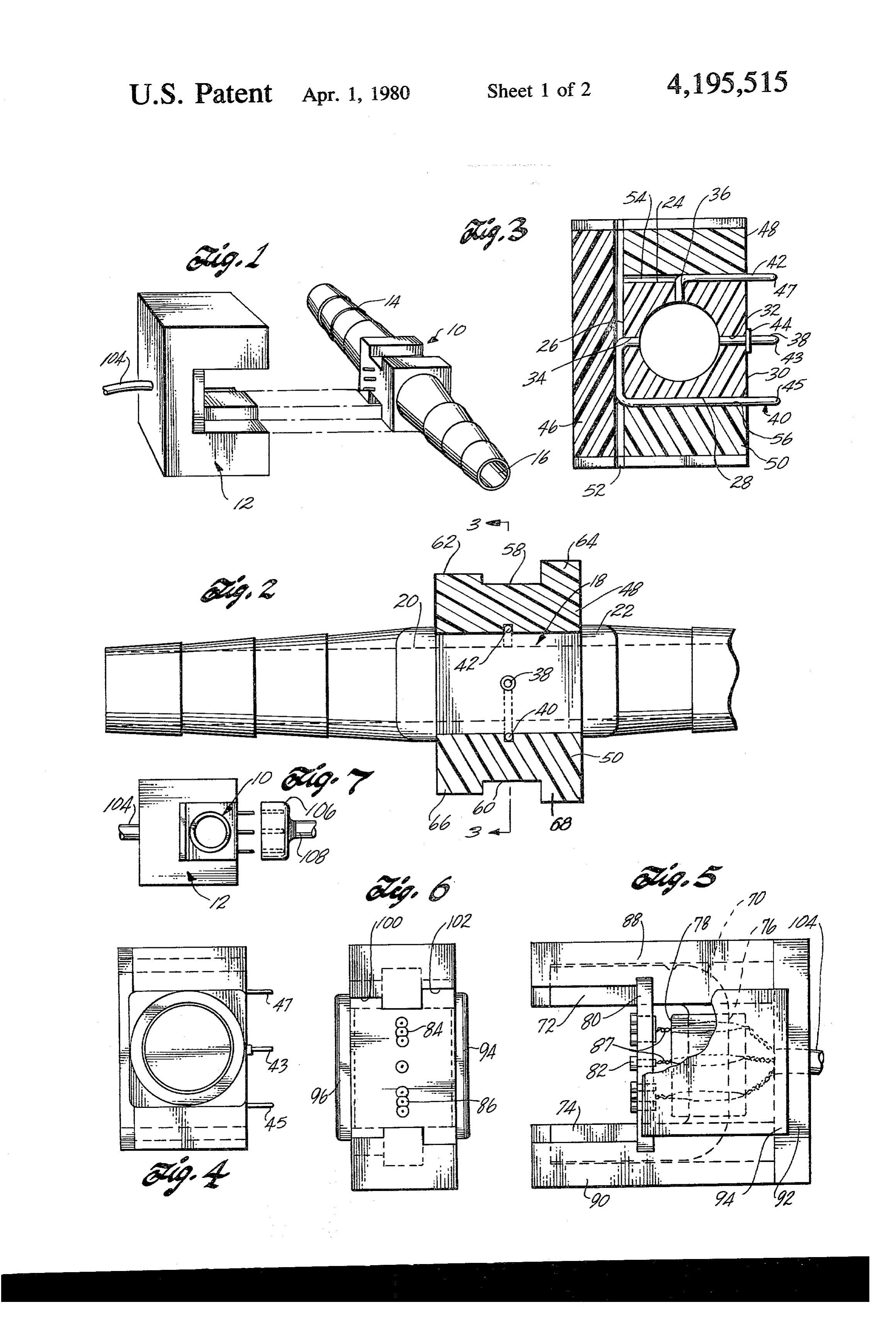
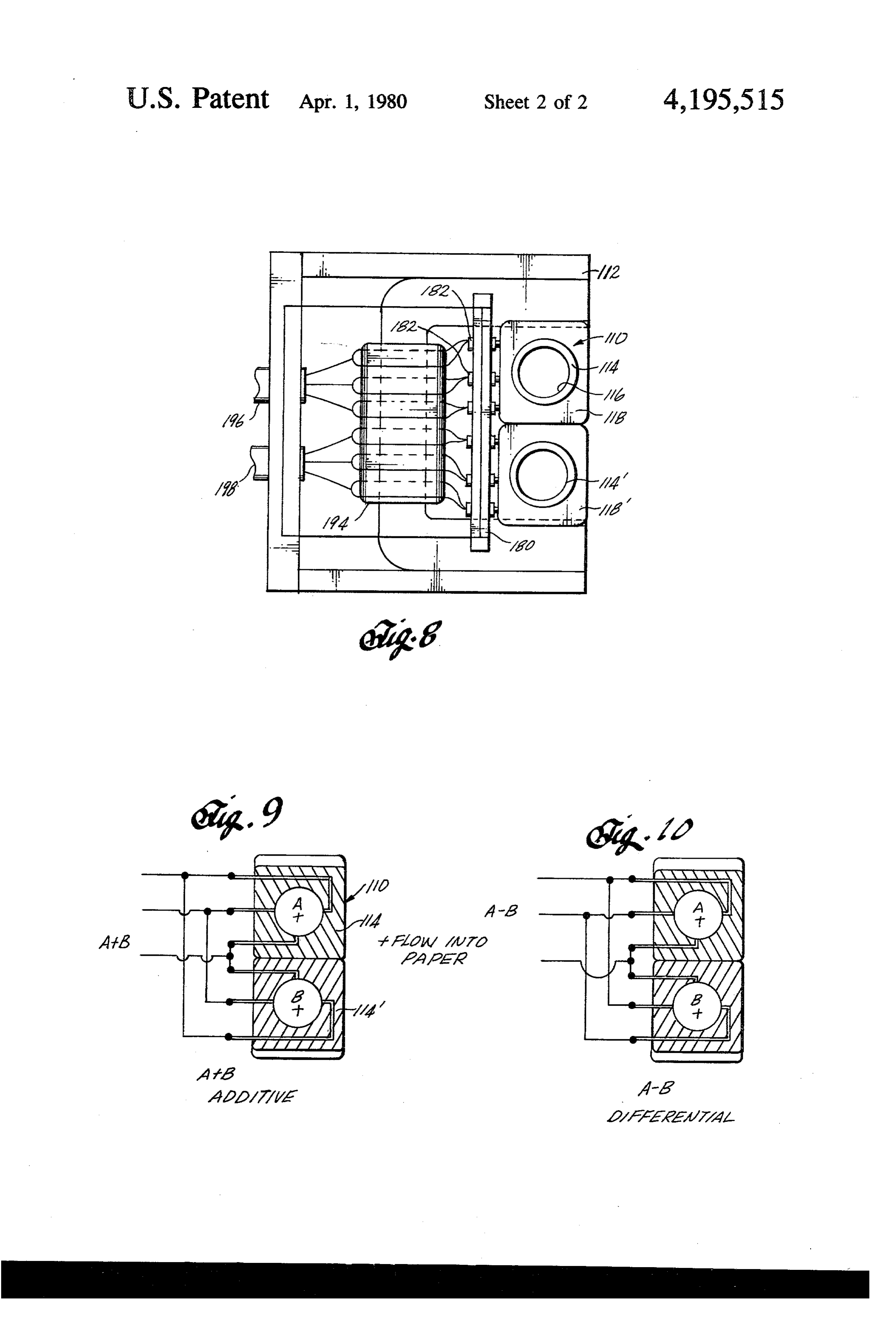
FIG. 8 is a side elevational view of a modified ar provided to accommodate measurement in different size rangement with the pair of lumens using a common flow lines. Where measurements are to be taken at more than one point in an extracorporeal circuit, a plurality of magnetic field; and
Page 2drawing sheetscan →
Page 3drawing sheetscan →
Page 4scan →
adapted to be connected at either end into an extracor
N LINE EECTROMAGNETEC FLOW poreal blood flow line, such as used to connect an artifi MEASUREMENT TRANSUCER cal heart and lung machine into a patient's circulatory system. The tubular member includes a central portion
CROSS REFERENCE TO RELATED 5 in which a set of electrodes extending through the walls APPLICATION of the tube are mounted in a common transverse plane. This application is a continuation-in-part of applica The shaped central portion is surrounded by a rectangular central block. Electrodes are brought out at one tion Ser, No. 700,176, filed June 28, i976, now aban side of the central block to form a plurality of male plug doned. 10 terminals. The magnet structure includes a C-shaped FIELD OF THE INVENTION magnetic core and a coil winding on the core, Parallel This invention relates to electromagnetic flow me the guide members extend along the outer ends of the core, ters, and more specifically relates to apparatus used in central block portion of the tubular member slidably the extracorporeal measurement of blood flow or other 15 engaging the guide members to hold the tubular mem ber in fixed position within the magnetic field between conductive liquids, the poles of the magnet. A female terminal connector BACKGROUND OF THE INVENTION mounted on the inside of the magnet structure receives The use of an electromagnetic flow meter to measure the male plug terminals of the tubular member when the blood flow is well known. The basic concept, for exam 20 unit is assembled. In a modification of the invention a ple, is described in U.S. Pat. No. 2,149,847. By passing single magnet structure is used to provide two flowne blood, either in a tube or blood vessel oriented at right ters by incorporating two removable tubular members angles to a magnetic field, an EMF is produced in a positioned within the same C-shaped electromagnet. direction mutually perpendicular to the magnetic field DESCRIPTION OF THE DRAWINGS and the direction of blood flow, since the blood has the 25 property of a moving conductor cutting through a mag For a more complete understanding of the invention netic field. The voltage generated is proportional to the reference should be made to the accompanying draw velocity of flow and therefore directly proportional to ings, wherein:
the volume rate of flow of the fluid. The voltage can be FIG. 1 is a perspective view of the flow meter in measured by electrodes positioned at diametrically op 30 disassembled condition;
posite points of the tube along a diameter extending FIG. 2 is a plan view partly in section of the flow perpendicular to the magnetic lines of the flux. meter;
Because the electrodes, magnet structure, and fluid FIG. 3 is a sectional view taken substantially on the passage must be maintained in fixed predetermined rela line 3-3 of FIG. 2;
tionship in order to maintain accurate calibration of the 35 FIG. 4 is an end view of the sensor portion with a flow measurement, it has been the practice heretofore to larger diameter tubular member;
assembly the tube, electrodes, and magnet structure as a FIG. 5 is a side view of the magnet portion of the unit and direct flow of blood or other conductive fluid through the tubular section in making flow measure flow meter;
ments. Such unitary structure has several disadvantages FIG. 6 is an end view of the magnet portion; and in extracorporeal use. First, it is difficult to sterilize FIG. 7 is an alternative embodiment of the present effectively after use. Also different size units must be invention;
FIG. 8 is a side elevational view of a modified ar provided to accommodate measurement in different size rangement with the pair of lumens using a common flow lines. Where measurements are to be taken at more than one point in an extracorporeal circuit, a plurality of magnetic field; and
FIGS. 9 and 10 show two alternative wiring arrange separate complete flow meter units are required. 45 ments for the double lumen arrangement of FIG. 8.
Summary of the invention detaled description
The present invention is directed to an improved Referring to FIG. 1, the flow meter sensor assembly electromagnetic measuring unit for use in making flow comprises two separable parts, a replaceable tubular measurements in an extracorporeal circuit. The units 50 are made into two separable parts which can be readily sensor member 10, and a magnet member 12. Details of the sensor member 10 are shown in FIGS. 2, 3, and 4, assembled made into two separable parts which can be and readily assembled and disassembled. One part includes a FIGS.details Sand of the magnet structure 22 are shown in 6. Sensor member 10 is designed to slidably tube with electrode sensors which may be made inex pensive enough to utilize it as a disposable part, or a 55 engage and electrically plug into the magnet member paert which can be readily and easily changed and ster i2, permittingto the sensor member, which is relatively ilized by conventional techniques. The other part of the inexpensive, be made disposable or easily removable assembly includes a magnet structurc for generating the atotubularprovide sterilization. The sensor member i0 includes required magnetic field. The two parts can be easily providingmember 14 having a constant diameter bore 16 assembled and disassembled and include quick discon of the tubular member 14 therethrough.
are tapered so
The outer ends as to be insert nect electrical connections for the electrodes. The same magnet structure can be used in combination with tubu able into plastic tubing. The outer perimeter of a central lar units of different sizes. By using a plurality of tubular section 18 of the tubular member 4 is square in cross parts in an extracorporeal circuit, measurements can be section and extends between a pair of spaced flange made at different points in the circuit by moving the 65 portions 20 and 22. The central section 18, which there magnet structure part from one tubular part to another. fore takes the form of a block, with the bore 16 provid This is accomplished, in brief, by a flow meter device ing an opening therethrough, has four flat surfaces 24, having a tubular member made of nonmagnetic material 26, 28, and 30 which terminate in shoulders formed by 5 the flange portions 20 and 22. The tubular member 14 of the magnet structure and a center connecting portion preferably is injection molded in a single piece from 76. The core is preferably made of laminated silicon suitable plastic material, such as Lexan. steel and is substantially square in cross section. A coil Axially aligned holes 32 and 34 extend through the or winding 78 is wound on the central section 76 of the walls of the tubular portion at the center of the surfaces core 70. The spacing or gap between the inner surfaces 30 and 26, respectively. The third hole 36 extends at of the legs 72 and 74 of the core corresponds to the right angles to the axis of the holes 32 and 34 through distance between the guide surfaces 58 and 60 of the the center of the surface 24. The holes 32, 34, and 36 lie sensor member, while the width of the core corresponds in a common transverse plant. Three electrodes 38, 40, to the distance between the guide ridges 62, 64, and 66, and 42 are provided having ends which are inserted in O 68. Thus the magnetic core 70 is adapted to slidably the respective holes 32, 34, and 36 and terminate flush engage the central section of the sensor member 10. with the inner surface of the bore 16. The electrode 38 An H-shaped pin socket plate 80 extends between the extends outwardly perpendicular to the surface 30 to legs 72 and 74 of the core, spanning the space between form an electrical connector or first male plug or pin 43. the legs. A plurality of female sockets are mounted on The electrode 38 has a flange 44 which engages the 15 the plate 80, including a socket 82 at the center adapted surface 30 to position the electrode axially and to pro to receive a plug end 43 of the electrode 38. Two vide an additional surface for cementing the electrode groups of three sockets each, indicated at 84 and 86, are in position. adapted to receive the plug ends 45 and 47 of the elec The electrode 40 is J-shaped to provide an end por trodes 40 and 42. The three sockets in each group are tion extending through the hole 34, a portion terminat 20 provided to accommodate the differences in electrode ing in a connector plug or pin 45 extending along and spacing resulting from different tubular sizes of the projecting beyond the surface 28, and a transverse por sensor section, there being typically three different tion extending along the surface 26. The electrode 42 is sizes, corresponding to FIG. 3 and FIG. 4, and to an L-shaped providing a portion extending into the hole 36 intermediate size.
and a portion terminating in a connector plug or pin 47 25 The magnet and coil are enclosed in a top plate 88, extending along and projecting beyond the surface 24. bottom plate 90, and end plate 92 which preferably are The electrodes are preferably made of stainless steel and made of molded plastic. A pair of side plates 94 and 96 plated with gold to form a noncorrosive low resistance are positioned on either side of the coil. The top and contact with the fluid being measured. bottom plates 88 and 90 form guide members and pro The electrodes 40 and 42 are locked in place by a 30 vide guide surfaces 100 and 102 on either side of the leg back plate 46, and by top and bottom plates 48 and 50. 72 of the core 70 which are offset by differing amounts The back plate 46, which has a width corresponding to from the inner surface of the core so as to accommodate the distance between the shoulders formed by the the guide ridges 62 and 64 of the sensor section. The flanges 20 and 22, is cemented to the surface 26 of the plates are cemented together to provide a unitary struc tubular member 14. The plate 46 has a groove 52 which 35 ture.
receives the portion of electrode 40 extending along the Because the leads from the electrical connections are surface 26, thereby securely locking the electrode 40 in positioned in the magnetic field of the magnet, the inter position in the hole 34. The upper plate 48 similarly has nal electrical connections from the socket 82 and socket a groove 54 for receiving the electrode 42. The upper groups 84 and 86, respectively are in the form of twisted plate 48 also extends between the shoulders formed by conductor pairs 87 extending from the socket terminals the flanges 20 and 22 and is cemented or otherwise toward the coil 70. The two conductors of each pair are secured to the surface 24, thereby locking the electrode brought out around either side of the coil and recon 42 in position. The bottom plate 50 is provided with a nected as a pair to leads in shield cable 104. The magnet groove 56 which receives the electrode 40. The bottom leads may be brought out through the same cable but plate 50 is cemented or otherwise attached to the sur 45 are separately shielded. The twisted pair of conductors face 28. are carefully positioned in a common plane on both The ends of the plate 46 and the outer surfaces of the sides of the coil so that no magnetic lines of flux link the upper and lower plates 48 and 50 form a continuous conductors to induce net currents in the conductors by guide surface, as indicated at 58 and 60, respectively. induction. This is essential to reduce "noise' in the The guide surfaces 58 and 60 terminate at either end in 50 electrode output leads that could swamp out the low projecting guide ridges 62, 64, 66, and 68. The ridges 64 level signal from the electrodes. and 68 are made higher than the ridges 62 and 66 to The cable 104 connects to a conventional electromag provide a keying effect so that the sensor section can netic flow instrument (not shown) such as the flow only be inserted in one way into the magnet section. meter instruments presently available on the market. Referring to FIG. 4 there is shown an end view of a 55 The signal voltage is measured between the opposing sensor section having a bore of larger diameter. The electrodes 38 and 40 while electrode 42 is connected to top, bottom, and side plates are made thinner so that the ground.
outer dimensions of the sensor section remain the same While the electrode connections are preferably made while the tubular member 14 is made relatively larger. from the tubular member to terminate on the inside of This results in the terminal ends of the electrodes being the magnet member, an alternative arrangement is more widely spaced than in the smaller diameter unit shown in FIG. 7. Here the tubular member 10 engages described in connection with FIGS. 2 and 3. Otherwise the magnet member 12 in the same manner but is rotated the assembly of the sensor member of FIG. 4 is substan through 180' so that the electrode terminal plug ends tially identical to that of FIGS. 2 and 3. project away from the magnet core. A separate socket Referring to FIGS. 5 and 6, the magnet section of the 65 connector 106 and shield cable 108 are used to complete fluid flow meter is shown in detail. The magnet struc electrical connections between the electrodes and the ture includes a C-shaped magnetic core having a pair of measuring instrument. Otherwise the construction of parallel end portions or legs 72 and 74 forming the poles FIG. 7 is substantially identical to that of FIG. 1.
Page 6scan →
In an alternative arrangement shown in FIGS. 8, 9, cal connections between the disposable sensor section and 10, a single magnet member 12 receives a dual and the electromagnetic section when the sensor section tubular sensor assembly 110. The magnet member is is moved into the gap between the poles of the core in similar to that described above in connection with a direction transverse to the central part of the core, and FIGS. 1, 5, and 6, except that the open space between means in the sensor section for electrically connecting the poles of the magnet core are made wider to accom the electrodes to the terminals of the connector section modate the dual tubular sensor assembly 10. The dual integral with the tubular member. tubular sensor assembly 110 includes a pair of tubular the2.electrodesThe apparatus of claim 1 wherein the inner ends of lie in a plane extending perpendicular to members 114 and i4'. Tubular members 14 and 14 have a constant diameter bore 116. Outer central por 10 the flux lines extending between the poles of the core tions 118 and 118'' are rectangular in cross section with when the winding is energized. 3. Apparatus of claim $ wherein the electromagnetic.
flat outer surfaces. Adjacent surfaces of the two central section includes a pair of parallel guide means extending portions are preferably cemented or otherwise secured aiong the legs of the C-shaped core, and the tubular together to form the unitary non-conductive body. Op member includes mating guide means slidably engaging posite outer surfaces preferably slidably engage the pole 15 faces of the magnet in the same manner as the single said parallel guide means to hold the tubular member in position when the sensor section is inserted between the tubular arrangement described above. Each tubular poles of the electromagnetic section. member 14 and 114 includes three electrodes which are arranged in the same manner as described above in 20 integral parallelofportions 4. Apparatus claim a wherein the electrodes have forming the male connector connection with FIGS. 3 and 4. A socket plate 180 has section and adapted to directly six female sockets 182 arranged to receive the ends of ceptor section when the sensor engage section the female re is mounted in the electrodes to permit removal of the dual sensor position.
assembly 110. Six pair of electrical leads 184 extend 5. Apparatus of claim wherein the electromagnetic from the sockets around either side of the electromag net 94 to a pair of output cables 196 and 198. 25 section includes pairs of conductors connected to the As shown in FIGS. 9 and 10, the two tubular mem terminals of said other connector section, the pairs of bers and associated electrodes can be wired to provide around conductors extending from the respective terminals a measure of the combined flow through the tubular of each the winding to an output cable, the conductors pair being twisted together between the termi members or a measure of the difference in flow. FIG. 9 shows the wiring arrangement for measuring the com 30 nals and winding and passing separately around oppo bined or additive flow rate and FIG. 10 shows the wir site sides of the winding.
ing arrangement for measuring the difference in flow 6. Apparatus of claim 1 wherein the disposable sensor. rates. section includes a second tubular member extending From the above description it will be seen that a parallel to said first mentioned tubular member, a pair of sensor assembly is provided for making extracorporeal 35 electrodes extending through the wall of the second blood flow measurements or the like which is arranged tubular member and terminating at diametrically oppo in two separable sections, one section providing the site7.points in said common transverse plane. blood flow passage and associated sensor electrodes, sensorThe apparatus of claim 1 wherein the disposable and the other section including the electromagnet for sectionsection to only includes keying means limiting the sensor one insertion position in the electromag producing the required magnetic field. The two sec 40 tions provide mechanical as well as electrical connec netic section.
8. A flow meter assembly comprising first and second tions between the two sections, permitting the magnet separable sections, the first section including a C-shaped section to be used interchangeably with a plurality of magnetic core having parallel end portions and a central electrode sensor sections. The electrode sections are relatively inexpensive compared to the magnet sections 45 transverse portion, a coil wound on the transverse por and therefore can be used as a disposable item or an from tion, and an electrical terminal connector supported easily replaceable item. This arrangement also permits the core, the second section including a tubular substitution of electrode sensor sections accommodat member, a pair of electrodes extending into the tubular ing different tube diameter sizes to be used with the member at diametrically opposite points of the tubular same magnet structure. 50 member, guide means slidably engaging the end por What is claimed is: tions of the magnetic core for guiding and supporting 1. A liquid flow meter device comprising a disposable the tubular member in position between the ends of the sensor section including a tubular member made of C-shaped ends of the core, the guide means when engaging the core holding the axis of the tubular member nonmagnetic material adapted to be connected into a fluid flow line, and a pair of electrodes extending 55 and the diametrical axis of the ends of the electrodes in through the wall of the tubular member and terminating mutually perpendicular position relative to the flux path on the inner surface at diametrically opposite points in a and between the ends of the core when the coil is energized, common transverse plane, and an electromagnetic sec an electrical terminal means connected to the elec tion including a C-shaped core forming a pair of oppos trodes for engaging said electrical terminal connector to ing poles with a gap between the poles and a winding on complete electrical connections to the electrodes when the core, a multiple terminal connector having a female the second section is inserted between the end portioris receptor section and a male plug section, one of said of9.theThe core.
apparatus of claim 8 wherein the electrodes connector sections being integral with the sensor sec include portions extending parallel to each other in a tion in the region of said electrodes, and the other sec common plane parallel to the flux path between the tion being mounted adjacent the gap between the poles ends of the core, the ends of said electrode portions of the C-shaped core, the two sections of the connector forming plug terminals directly engaging each other by inserting the plug section into trical terminal connector of the insertable first into the elec section.
the receptor section to complete electrical and mechani
Page 7scan →
10. The apparatus of claim 9 further including a third 7. The sensor assembly of claim 16 wherein the body electrode extending into the tubular member at a point includes keying means limiting the sensor assembly to between said pair of electrodes, the third electrode only one insertion position in the magnet structure. lying in said common transverse plane with the pair of 18. A replaceable sensor assembly for a magnetic electrodes and having an end portion forming a terminal 5 fluid flow measuring instrument comprising a tubular directly insertable in the electrical connector of the first portion forming a fluid flow passage and a mounting section. portion surrounding the tubular portion, the mounting 1. Apparatus of claim 8 wherein the second section portion having a pair of spaced parallel longitudinal includes a second tubular member extending parallel guide surfaces extending perpendicular to and on either and integral with the first-mentioned tubular member, a 10 side of the axes of the tubular portion for guiding the pair of electrodes extending into the second tubular assembly into position in the magnet structure of mea member at diametrically opposite points, the longitudi suring instrument, and three conductive electrodes hav nal axis of the two tubular members lying in a common ing ends terminating in the tubular portion and exposed plane, the guide means holding the axis of the second to fluid passing therethrough, said ends lying in a com tubular member and the diametrical axis of the ends of 15 mon plane transverse to the axis of the tubular portion, the electrodes in mutually perpendicular position rela two of said ends being positioned opposite each other tive to the flux path between the ends of the core when along a common axis extending parallel to the longitudi the coil is energized, the flux extending parallel to said nal guide surfaces and the third end being in a position common plane of the axis of the two tubular members. intermediate said two ends, said electrodes having ter 12. A flow meter assembly comprising first and sec- 20 minal ends projecting outside the mounting portion in ond separable sections, the first section including a C parallel relationship to each other in direction parallel shaped magnetic core having parallel end portions and to said longitudinal guide surfaces, to form an electrical a central transverse portion, and a coil wound on the connector.
transverse portion, the second section including a tubu 19. The sensor assembly of claim 18 wherein the lar member, a pair of electrodes extending into the tubu- 25 mounting portion includes means for keying the sensor lar member at diametrically opposite points of the tubu assembly so that the sensor assembly can be positioned lar member, guide means slidably engaging the end in the magnet structure in only one way. portions of the magnetic core for guiding and support 20. A flow meter assembly comprising first and sec ing the tubular member in position between the ends of ond separable sections, the first section including a C the C-shaped core, the guide means when engaging the 30 shaped magnetic core having parallel end portions and ends of the core holding the axis of the tubular member a central transverse portion, and a coil wound on the and the diametrical axis of the ends of the electrodes in transverse portion, the second section including a pair mutually perpendicular position relative to the flux path of tubular members, a pair of electrodes extending into between the ends of the core when the coil is energized, each of the tubular members at diametrically opposite the electrodes including portions extending parallel to 35 points of the tubular members, guide means slidably each other in a common plane parallel to the flux path engaging the end portions of the magnetic core for between the ends of the core, the ends of said electrode guiding and supporting the tubular members in position portions forming terminals projecting from one side of between the ends of the C-shaped core, the guide means the second section, and electrical connector means for when engaging the ends of the core holding the axis of engaging the terminals to provide external electrical 40 each of the tubular members and the diametrical axis of connections to the electrodes. the ends of the corresponding electrodes in mutually 13. Apparatus of claim 12 wherein said terminals perpendicular position relative to the flux path between extend away from the coil when the two sections are the ends of the core when the coil is energized, the assembled. electrodes including portions extending parallel to each 14. Apparatus of claim 12 wherein said terminals 45 other in a common plane parallel to the flux path be extend toward the coil when the two sections are assem tween the ends of the core, the ends of said electrode bled, the connector means being mounted on the first portions forming terminals projecting from one side of section between said end portions of the core for engag the second section, and electrical connector means for ing the terminals. engaging the terminals to provide external electrical 15. Apparatus of claim 14 further including pairs of 50 connections to the electrodes.
conductors joined to and extending from each terminal 21. The flow meter assembly of claim 20 wherein the of the connector means past the coil and away from the second section includes means for keying the second coil, the conductors forming each pair extending on section into the first section in only one way. opposite sides of the coil. 22. A replaceable sensor assembly for a magnetic 16. A replaceable sensor assembly for a magnetic 55 flow meter of the type using a magnet structure for flow meter of the type using a magnet structure for producing a magnetic field between a pair of spaced producing a magnetic field between a pair of spaced poles, comprising a block having an opening extending poles between which the fluid is directed, comprising a therethrough, and three conductive electrodes sup non-conductive body having a pair of spaced parallel ported in said block in a common plane extending sub passages extending through the body, the body being 60 stantially perpendicular to the direction of the opening shaped to slidably engage the magnet structure between with one end of each electrode projecting outside the the poles, two groups of three electrodes lying in a block in said plane to form three parallel connector common plane extending perpendicular to said pas pins, the other end of the middle one of the three elec sages, the electrodes of each group intersecting respec trodes intersecting the opening at a first point, one of tive ones of said passages at three spaced points around 65 the outer two electrodes being bent such that the other the circumference of the associated passage, with two end of the electrode intersects the opening at a point on of the electrodes intersecting the passage opposite each the opposite side of the opening and in alignment with other along a line. the first electrode, the other of the outer two electrodes
Page 8scan →
4,195,515 10 being bent such that the other end of the electrode the the opposite side of the opening and in alignment with first electrode, the other of the outer two electrodes intersects the opening at a point on the periphery of the opening that is intermediate the intersecting points of being bent such that the other end of the electrode the other two electrodes; and wherein the block has intersects the opening at a point on the periphery of the elongated guide surfaces adapted to slidably engage the 5 opening that is intermediate the intersecting points of magnet structure, the guide surfaces extending parallel the otherthrough two electrodes; and further including a second to the connector pins on opposite margins of the block openingand a second the block parallel to the first opening, group of three electrodes mounted in the for guiding the block and associated pins into and out of block intersecting the second opening respectively on a terminal engaging position in the magnet structure.
23, Apparatus of claim 22 further including tubular 10 opposite sides of the second opening and at an interme means projecting from the block in alignment with said diate point of the second opening. 27. Apparatus of claim 26 further including a pair of opening for passing fluid through the opening.
24. Apparatus of claim 22 wherein said opening in the tubular means projecting from the block in alignment block is cylindrical, the axis of the cylinder being per respectively with the two openings for passing fluid pendicular to the plane of the electrodes, the ends of 15 through each of the openings. 28. A replaceable sensor assembly for a magnetic two of the electrodes intersecting the cylindrical open ing at diametrically opposite points and the third elec flow meteraofmagnetic the type using a magnet structure for trode intersecting the cylindrical opening along a diam producing field between a pair of spaced poles, comprising a block having an opening extending eter perpendicular to the diameter extending between therethrough, and three conductive electrodes sup said diametrically opposite points. 20 ported in said block in a common plane extending sub 25. Apparatus of claim 22 wherein said guide surfaces stantially of the block extend substantially parallel to each other perpendicular to the direction of the opening and in a direction perpendicular to the central axis of with one end of each electrode projecting outside the the opening. block in said plane to form three parallel connector 26. A replaceable sensor assembly for a magnetic 25 pins, the other end of the middle one of the three elec flow meter of the type using a magnet structure for trodes intersecting the opening at a first point, one of producing a magnetic field between a pair of spaced the outer two electrodes being bent such that the other poles, comprising a block having an opening extending end of the electrode intersects the opening at a point on therethrough, and three conductive electrodes sup the the opposite side of the opening and in alignment with ported in said block in a common plane extending sub- 30 first electrode, the other of the outer two electrodes stantially perpendicular to the direction of the opening being bent such that the other end of the electrode with one end of each electrode projecting outside the intersects the opening at a point on the periphery of the block in said plane to form three parallel connector opening that is intermediate the intersecting points of pins, the other end of the middle one of the three elec the other two electrodes; and wherein the block in trodes intersecting the opening at a first point, one of 35 cludes keying means limiting the sensor assembly to a the outer two electrodes being bent such that the other single orientation between X the spaced poles.
end of the electrode intersects the opening at a point on
Page 9scan →
United states patent and trademark office
Certificate of correction
INVENTOR(S) : OWen C. Smoll
It is certified that error appears in the above-identified patent and that said Letters Patent are hereby Corrected as shown below: y
Column l, line 52, delete "made into two separable parts which can be readily assembled";
line 56, "Paert" should be --part--;
line 56, "changed" should be -- cleaned--.
Column line 2, "artifical" should be --artificial--. Column line 9, "plant" should be --plane--. Column line 45, "pair" should be --pairs--. Column line l4, the Should be -- a--. signed and sealed this
Seal
Eighteenth Day of November 1980
Sidney a. damond
Attesting Officer Commissioner of Patents and Trademarks
Provenance
- Collection
- Patents citing this work
- Pages
- 9
- Method
- pdftotext (the PDF's own text layer) + pdftoppm 300dpi page scans
- Patent office record
- patents.google.com →
- Source
- Google Patents citing-documents table
- Assignee
- Smoll Owen C
- Published
- 1980-04-01
- Transcribed from
- patentimages.storage.googleapis.com →