

patent · US4224045A
Cryogenic system for producing low-purity oxygen
23 September 1980
Text
Page 1scan →
United States Patent (19)
Olszewski et al.
54 cryogenc system for producing
Low-purity oxygen
75 Inventors: Walter J. Olszewski, Tonawanda;
John H. Ziemer, Grand Island, both (73) Assignee: Union Carbide Corporation, New
York, N.Y.
(51) Int. C.’................................................. F25J 3/04 (52) U.S. C. ....................................... 62/30; 60/39.55;
58) Field of Search ............................. 62/135, 29, 30;
2,520,862 8/1950 Swearingen ..... ... 62/29 3,605,422 9/1971 Pryor et al............................... 62/13 3,693,347 5/1971 Kydd et al. . 60/39.55 3,731,495 5/1973 Coveney .................................. 62/29 3,982,878 10/1975 Yamane et al. ..................... 60/39.55 Primary Examiner-Norman Yudkoff
Attorney, Agent, or Firm-Steven J. Hultquist
Low-purity oxygen is produced by fractional distilla tion of liquefied air. A gas turbine, powered in part by waste nitrogen from the distillation, supplies energy to compress the feed air. Compressing the waste nitrogen prior to turbine expansion provides an increase in en ergy efficiency.
22 Claims, 7 Drawing Figures
Drawings
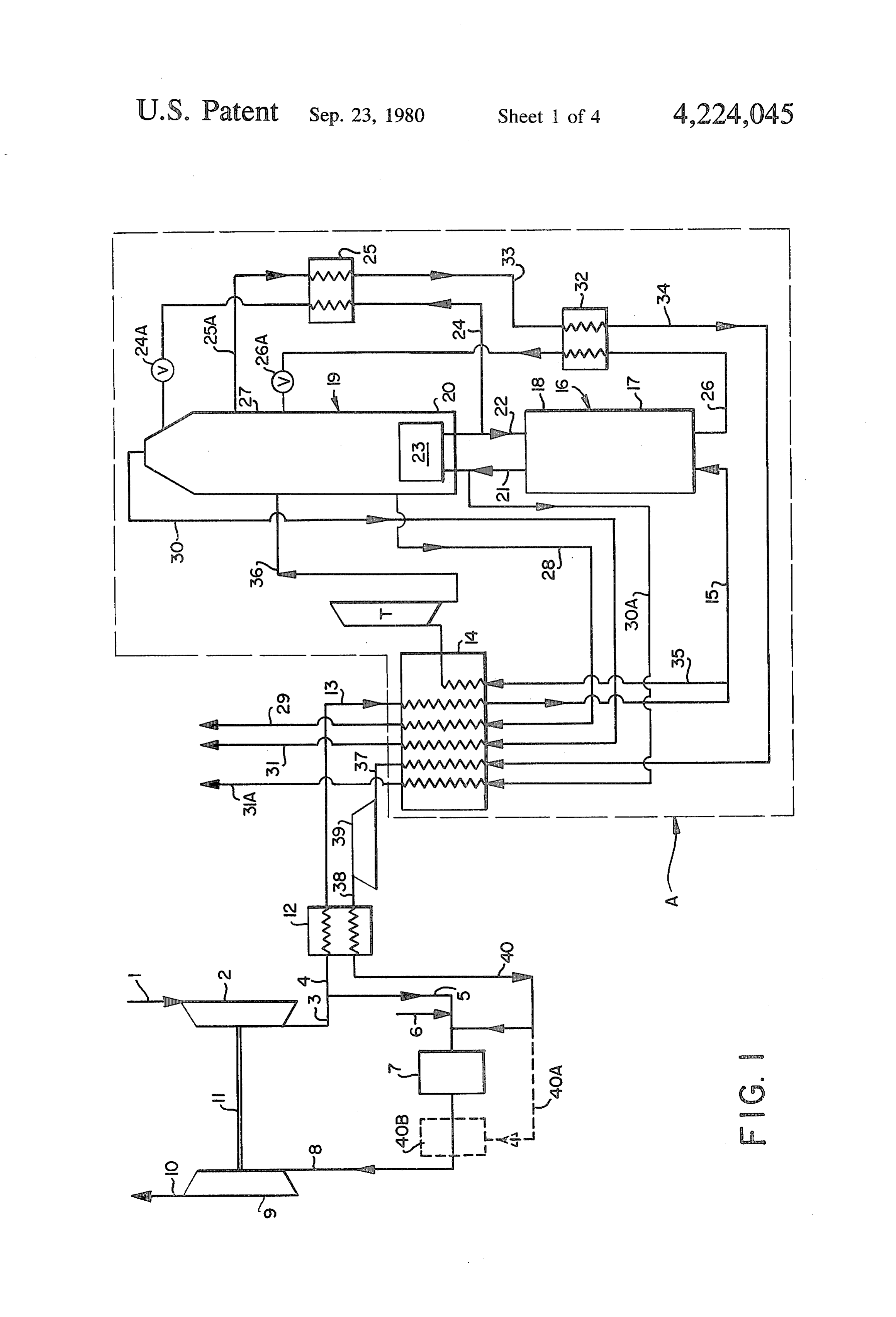
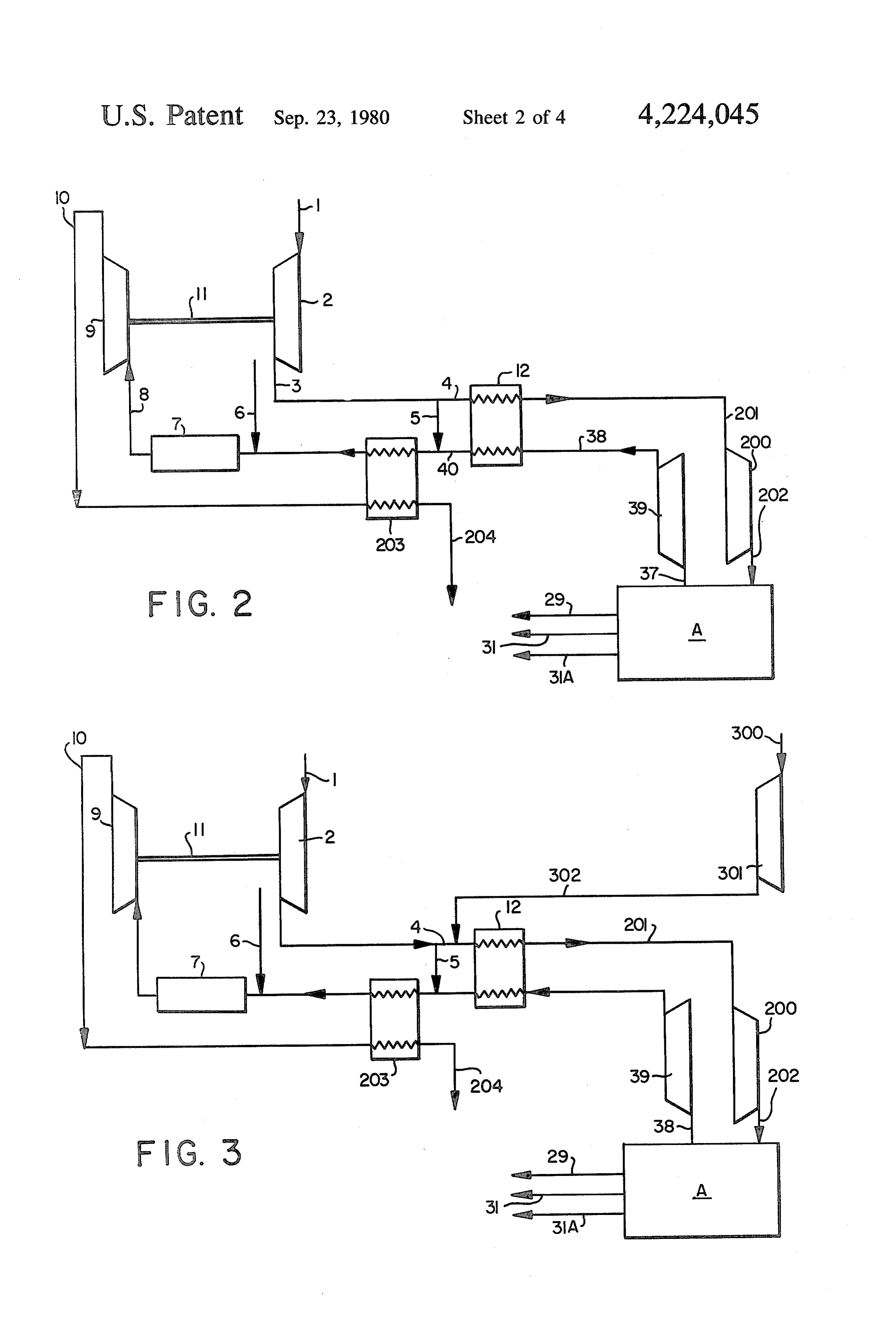
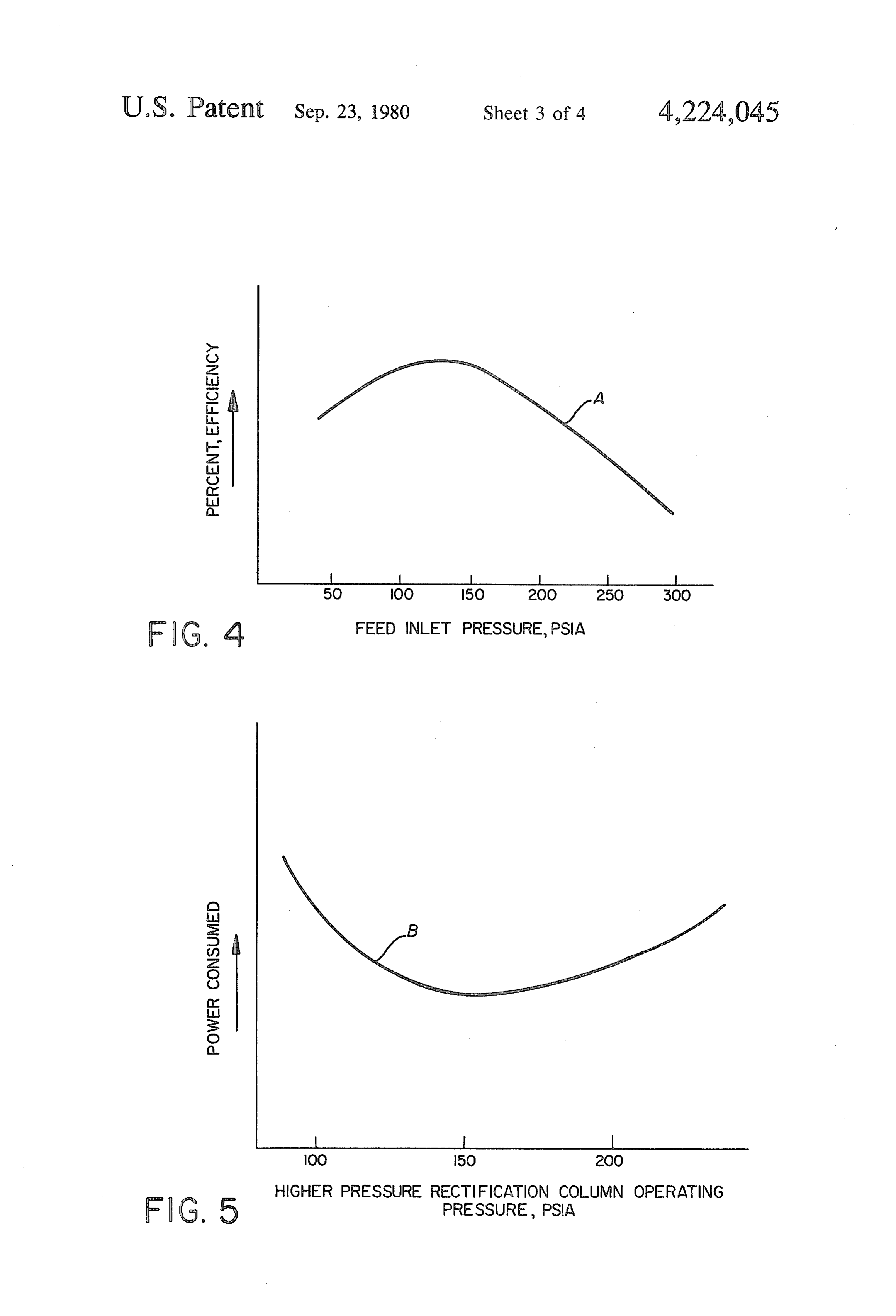
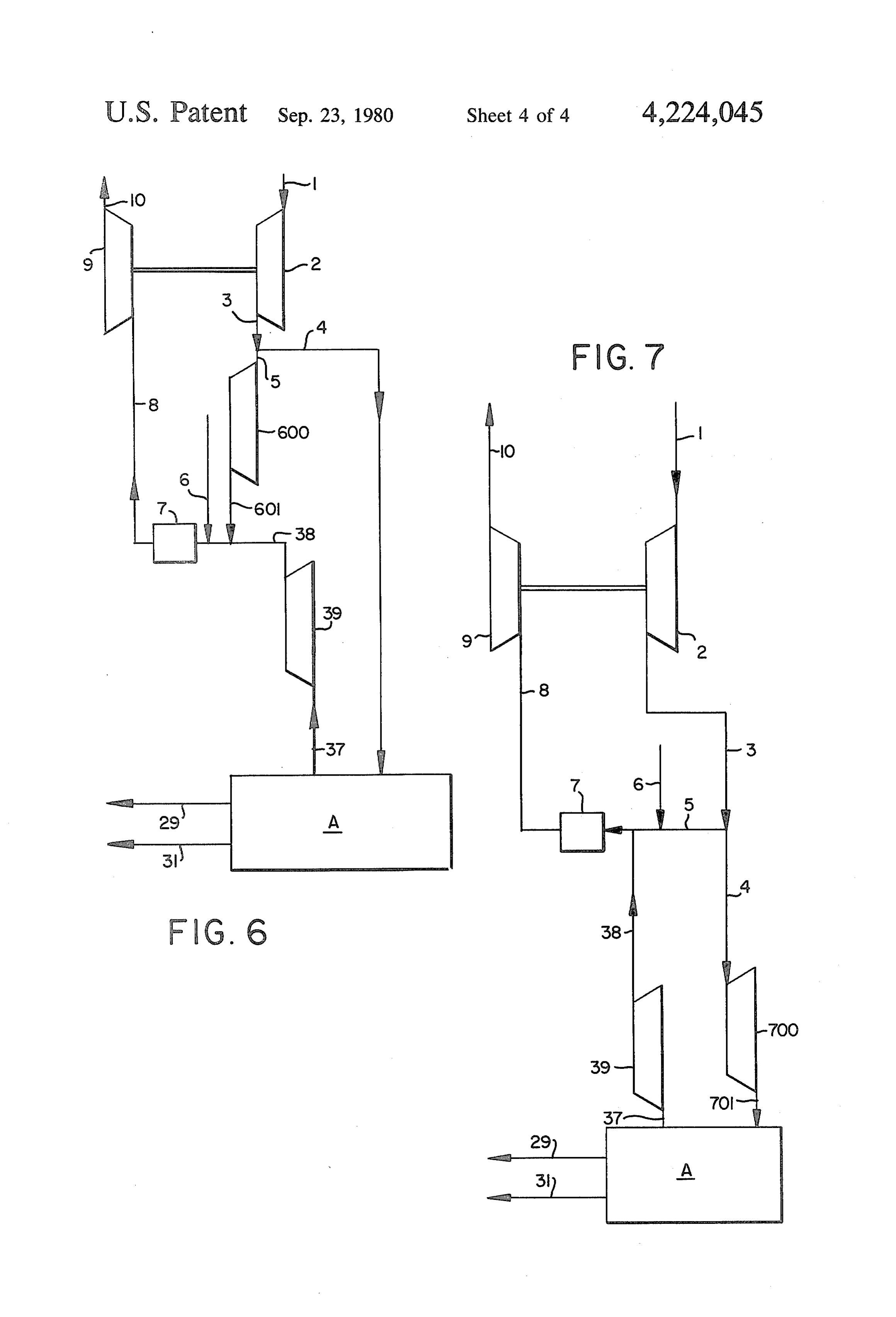
FIG. 3 is the same as FIG. 2 except that auxiliary air Oxygen compressor 301 has been added. The equipment illus Conduit Flow Rate
Page 2drawing sheetscan →
Page 3drawing sheetscan →
Page 4drawing sheetscan →
Page 5drawing sheetscan →
Page 6scan →
quires that the pressure of the gaseous mixture ex
CRYOGENIC SYSTEM FOR PRODUCING panded in the power turbine be no greater than that of LOW-PURITY OXYGEN the nitrogen mixed . . with the combustion mixture.
Background
Hence, Swearingen is also unable to independently set the pressure of the turbine inert gas and higher pressure
This invention relates to the low-temperature frac column to achieve optimum operation of both the tionation of air to obtain low-purity oxygen and nitro power turbine and the distillation system. Swearingen, gen-rich products. The term "low-purity-oxygen" as has a further disadvantage in that the nitrogen stream used throughout the present specification and claims is intended to mean a product having an oxygen content 10 isremoved from the higher-pressure rectification column unavailable for feeding to the lower-pressure rectifi of less than 99.5 mole percent. cation column, thereby depriving that column of reflux It is believed that very large quantities of low-purity oxygen will be required by processes now being devel intheproportion to the amount of nitrogen removed from higher-pressure stage.
oped for converting coal to liquid or gaseous products.
Another use for low-purity oxygen is in a process for 15 OBJECTS converting refuse to useful gaseous products as de Accordingly, it is an object of this invention to cryo scribed in Anderson, U.S. Pat. No. 3,729,298. Hence, a genically produce low-purity oxygen from air using a process for producing low-purity oxygen in large quan tities at low cost is desirable. double-column distillation system and a nitrogen A common system for low temperature fractionation 20 quenched power turbine in, such manner that either the employs a higher-pressure rectification column having distillation system or power turbine can operate at least its upper end in heat exchange relation with the lower 20 psi closer to its optimum pressure. end of a lower-pressure rectification column. Cold com It is another object of this invention to cryogenically pressed air is separated into oxygen-enriched and nitro produce low purity oxygen using a double column dis gen-rich liquids in the higher-pressure column, and 25 tillation system and a nitrogen quenched power turbine these liquids are transferred to the lower-pressure col in such manner that both the distillation system and umn for separation into nitrogen-rich and oxygen-rich power turbine can operate substantially at their respec products. Examples of this double-column distillation tive optimum pressures.
system appear in Ruheman's "The Separation of It is a further object of the invention to cryogenically produce low-purity oxygen from air using a double
Large quantities of energy are required to compress column distillation system and a nitrogen-quenched the feed air for such a process. Hence, in these times of rising energy cost, a saving of energy is important. power turbine with reduced energy requirements. Coveney, in U.S. Pat. No. 3,731,495, discloses a system SUMMARY OF THE INVENTION for reducing the energy required by the double-column 35 These and other objects are achieved by the present distillation system by use of a nitrogen-quenched power turbine. A portion of the compressed feed air is mixed invention one aspect of which comprises: with fuel and combusted. The hot combustion mixture temperaturea process for producing low-purity oxygen by low is then quenched with waste nitrogen-rich gas from the rectification of air comprising: lower-pressure column, and the resulting gaseous mix (a) compressing feed air to at least 85 psia, ture is expanded in a power turbine. The expansion (b) dividing the compressed air into a first part and provides energy to compress the feed air to the system. second part,
A disadvantage of the Coveney process is that the pres (c) mixing said first part as oxidant for a combustion sure of the gaseous mixture expanded in the power stream with fuel, turbine can be no higher than that of the waste nitrogen 45 (d) igniting said combustion stream in a combustion mixed with the combustion gases. Hence, it would be zone at ignition pressure of at least 80 psia to heat impossible, in the Coveney process, to operate both said combustion stream, lower pressure column and turbine at their respective (e) expanding the heated combustion stream in a optimum pressures, unless both had the same optimum power turbine to lower pressure with the produc pressure. However, it has been found that commercially 50 tion of external work, available power turbines usually have optimum inlet (f) recovering at least part of said external work as pressures exceeding the optimum operating pressure of energy for said compressing of feed air, the lower-pressure rectification column in a typical (g) cooling said second part of compressed air, air-separating system. This is true even for most of the (h) introducing the cooled air to a higher pressure higher-than-normal pressures used in the lower-pres 55 sure rectification column of the Coveney process. rectification stage having its upper end in heat Hence, Coveney's invention is unable to achieve opti exchange relation with the lower end of a lower mum operation of both the distillation system and the pressure rectification stage, power turbine. (i) separating said cooled air into oxygen-enriched Another cryogenic air-separation system using a and nitrogen-rich liquids in said higher pressure power turbine is disclosed by Swearingen, in U.S. Pat. rectification stage,
No. 2,520,862. The Swearingen process mixes waste (j) transferring at least part of said liquids from step (i) nitrogen-rich gas obtained from the higher-pressure to said lower pressure rectification stage for separa column with a portion of compressed feed air. Fuel is tion into low purity oxygen and nitrogen-rich then injected into the mixture, and the mixture is com 65 gases. . . . . . . . . .
busted and expanded in a power turbine, thereby pro (k) operating said lower-pressure rectification stage viding energy to compress the feed air for the system. at pressure at least 20 psi lower than the step (d) Like the Coveney process, Swearingen's process re ignition pressure. . . . . . . . ."
Page 7scan →
(l) discharging a low-purity oxygen product stream The term "cooling' as used throughout the present and at least one nitrogen-rich gas stream from said specification and claims is intended to mean cooling a lower pressure rectification stage, stream to near its dew point. A preferred method of (m) compressing at least part of the nitrogen-rich gas cooling the air fed to the double-column distillation discharged in step (I) to pressure at least equal to 5 system is by heat exchange with cold products of the the step (d) ignition pressure, and distillation system in a reversing heat exchanger well (n) flowing the compressed nitrogen-rich stream into known in the art. The cooling step also removes high the combustion stream, upstream of said power boiling impurities, such as water and carbon dioxide turbine. from the feed air.
Another aspect of the invention comprises: O The term "efficiency' as used throughout the present apparatus for producing low-purity oxygen by low specification and claims with regard to a power turbine temperature rectification comprising: is intended to mean the ratio of the turbine shaft work (a) a compressor for compressing feed air to pressure output to fuel heat input.
of at least 85 psia, The term "optimum inlet pressure', as used through (b) a combustion system comprising a combustion 15 out the present specification and claims is intended to chamber, conduit means for flowing a first part of mean the inlet pressure at which a power turbine attains compressed feed air from compressor (a) to said its maximum efficiency for a given set of inlet condi combustion chamber, means for introducing fuel to tions other than pressure.
said combustion chamber, and conduit means for The term "optimum operating pressure' as used flowing combusted gas from said combustion throughout the present specification and claims is in chamber to, tended to mean the operating pressure of a rectification (c) a turbine for expanding the combusted gas to stage for which the air-separation system's energy re lower pressure so as to produce external work, quirements are a minimum for a given oxygen product (d) means for transferring external work of turbine (c) stream delivery pressure.
to compressor (a), 25 The term "product stream' as used throughout the (e) means for cooling a second part of compressed present specification and claims is intended to mean a feed air, stream separated in the air-separation column and re (f) a double rectification column comprising a higher moved from the air-separation system that is not mixed pressure stage for operation at at least about 85 with the first part of compressed air and expanded in the psia, a lower-pressure stage, and a heat exchanger 30 power turbine.
joining the upper end of the higher-pressure stage As used herein, all percent compositions refer to mole and the lower end of the lower-pressure stage, percents.
separate conduit means for transferring oxygen The preferred percent oxygen of the low-purity oxy enriched and nitrogen-rich liquids from the higher gen product is above 90 percent with between 95 and pressure stage to the lower-pressure stage, 35 99.5 percent being most preferred. (g) conduit means for flowing the cooled cleaned IN THE DRAWINGS second part of the compressed feed air to the high er-pressure stage for rectification therein, FIG. 1 is a schematic flowsheet of a complete system (h) a compressor for compressing nitrogen-rich gas to for producing low-purity oxygen in accordance with a pressure of at least 85 psia, preferred embodiment of the invention. (i) conduit means for flowing nitrogen-rich gas from FIG. 2 is a schematic flowsheet of an embodiment of the lower-pressure rectification stage to compres the invention wherein the air fed to the air separation sor (h), system is further compressed after the first part is split (j) conduit means for flowing nitrogen-rich gas from off for the combustion stream.
compressor (h) to combustion system (b), and 45 FIG. 3 is a schematic flowsheet of an embodiment of (k) conduit means for discharging low-purity oxygen the invention wherein an additional air feed stream is from said lower-pressure rectification stage. supplied to the air-separation system. This invention is predicated on the finding that per FIG. 4 shows a typical efficiency curve for power forming the seemingly inefficient step of boosting the turbines.
pressures of the nitrogen-rich gas prior to injecting it 50 FIG. 5 shows energy requirements for typical dou into the combustion stream for expansion in the power ble-column air separation plants. turbine substantially increases in the total energy effi FIG. 6 is a schematic flowsheet of an embodiment of ciency of the process. One would expect that compress the invention wherein the first part of the compressed ing the nitrogen-rich stream, only to expand it again, feed air is further, compressed prior to entering the would cause a net loss of energy efficiency, since the 55 combustion zone.
compression process, which must be performed at less FIG. 7 is a schematic flowsheet of an embodiment of than 100 percent energy efficiency, would seem to be a the invention wherein the air fed to the air separation wasteful intermediate step. However, it has been found system is work expanded after the first part is split off that the inefficiency of performing the extra nitrogen for the combustion system.
compression step is more than compensated for by the DETAILED DESCRIPTION OF THE gain in efficiency of being able to operate either the INVENTION power turbine or the air separation system closer to its optimum pressure. By compressing the nitrogen-rich Referring now to FIG. 1, this embodiment of the gas stream to a pressure approximating the optimum invention comprises an air-separation system, A, en inlet pressure of the power turbine, the entire combus 65 closed by dotted lines, and a power system, drawn out tion system can also operate at that pressure, and the side the dotted lines. The system functions as follows. gaseous stream expanded in the power turbine can be at Feed air enters base compressor 2 by conduit 1 and is the turbine's optimum inlet pressure. compressed to a pressure of at least 85 psia, and prefera 8 bly to between 100 and 250 psia. After flowing from This is a preferred method of cooling and simulta compressor 2 in conduit 3, the compressed feed air is neously removing impurities from air fed to the air divided into a first part in conduit 5 and a second part in separation system. The feed is cooled while high boiling conduit 4. The handling of the second part, which is fed impurities, such as water and carbon dioxide, are desub to the air separation system, will be described later. The limed and deposited onto the walls of the reversing heat first part of the compressed feed air is used to form a exchanger. Before the solid deposit plugs the heat ex combustion stream. The term "combustion stream' as changer, the feed air stream is switched to a second used throughout the present specification and claims is passageway by valve and conduit means (not shown), intended to refer to the gas flowing from the point and a cold stream, the contamination of which is of no where the first part of the compressed feed air is split 10 consequence, such as the waste nitrogen stream, is from the second part to the inlet of the power turbine. passed through the passageway of the reversing heat In FIG. 1, the “combustion stream' comprises the gases exchanger containing the solid water and carbon diox flowing through conduit 5, combustion chamber 7 ide deposits, causing these impurities to vaporize and (where combustion takes place) and conduit 8. As fuel is leave the heat exchanger. Before the second passage added to the first part of the compressed feed air up 15 way handling the feed air stream plugs, the feed air is stream of the combustion chamber, it becomes part of diverted to the cleaned passageway and the out-going the "combustion stream' as defined herein. Fuel is fed stream is used to remove impurities from the second into the first part of the compressed feed air stream, i.e. passageway. Of course, any means for cleaning and the combustion stream, by conduit 6. This fuel may cooling the feed streams will suffice, such as regenera comprise any clean burning combustible fluid material, 20 tive heat exchangers, gel traps, molecular sieves, exter as for example, oil or gas mixture including a combusti nal refrigeration, or combinations thereof. ble such as methane or carbon monoxide. Sufficient air The cooled feed air then flows by conduit 15 to high is introduced through conduit 5 to ensure complete er-pressure rectification stage 16, where it is rectified oxidation of the fuel; typically a 20-30 percent stoichio against colder liquid to produce oxygen-enriched liquid metric excess of air is used for this purpose. The com 25 at lower end 17 and nitrogen-rich gas at upper end 18. bustion stream then flows to combustion zone 7 where Upper end 18 of rectification stage 16 is in heat ex the mixture is ignited to raise the temperature of said change relationship with lower end 20 of lower-pres combustion stream. Ignition takes place at ignition pres sure rectification stage 19 by conduits 21 and 22 and sure of at least 80 psia. Conduit 8 then conducts the hot heat exchanger 23, a condenser-evaporator well known combustion stream into power turbine 9 where the hot 30 in the art. Nitrogen-rich gas flows via conduit 21 to heat combustion stream is expanded to produce external exchanger 23, where it is condensed against colder work. The expanded gas then leaves power turbine 9 by low-purity oxygen, the formation of which will be dis conduit 10. cussed later. The condensed nitrogen-rich material is Compressed waste nitrogen, i.e. nitrogen-rich gas then refluxed by conduit 22 to column 16, thereby pro which is not to be recovered as a product stream, is 35 viding the colder liquid to rectify the feed air. A portion mixed with the combustion stream prior to its expansion of the condensed nitrogen-rich material flows by con in turbine 9. The waste nitrogen generation, compres duit 24 to lower pressure rectification column 19. Be sion and manner of mixing with the combustion stream fore entering column 19, the stream is expanded to will be described later. lower pressure in valve 24A. The nitrogen-rich material Work obtained from power turbine 9 is used to drive in conduit 24 may be cooled by outgoing material in base compressor 2, which may be directly connected to heat exchanger 25.
turbine 9 by shaft 11. Alternately, work may be trans The oxygen-enriched liquid that forms in lower end ferred to compressor 2 by a system of gears, or turbine 17 of stage 16 is introduced to lower-pressure stage 19 9 could drive an electrical generator which supplies by conduit 26, after being expanded to lower pressure electrical energy to an electric motor to drive compres 45 through valve 26A. This oxygen-enriched liquid may be sor 2. Any means of transferring work from turbine 9 to cooled by outgoing material in heat exchanger 32. compressor 2 is acceptable. The work obtained from The lower-pressure rectification stage is operated at power turbine 9 may also be used to drive waste nitro pressure at least 20 psi and preferably at least 30 psi gen compressor 39 through any work transfer means, as lower than the ignition pressure. The feeds to lower discussed above for transferring work to base compres 50 pressure rectification stage 19 are rectified to produce sor 2. low-purity oxygen liquid at lower end 20 and nitrogen Further energy may be recovered from the gases rich gas at upper end 27. The low purity oxygen is exiting power turbine 9 in conduit 10. Examples of how boiled against hotter nitrogen-rich material in heat ex to recover further energy from such gases are described changer 23 for upward flow through column 19. A by Coveney, U.S. Pat. No. 3,731,495, the entire contents 55 portion of the low-purity oxygen vapor is discharged by of which is incorporated herein by reference. Coveney conduit 28, used to cool incoming feed air in heat ex also describes arrangements for constructing the com changer 14, and discharged from the system by conduit bustion chamber, turbine, and compressor as one unit, 29 as a product stream. A product stream of nitrogen which would be a useful way to implement this inven rich gas may be discharged from upper end 27 of stage tion. 60 19 by conduit 30. This nitrogen-rich product stream, The second part of the compressed feed air flows by which can also be used to cool incoming products in conduit 4 into heat exchanger 12 where it may be par heat exchanger 14 is discharged from the system by tially cooled by the waste nitrogen leaving the air sepa conduit 31. If desirable, a product stream of nitrogen ration system. This air may be further cooled in a water rich gas may be withdrawn from conduit 21 by conduit cooled heat exchanger, not shown. The partially cooled 65 30A, used to cool incoming air in heat exchanger 14, air then enters the air-separation system by conduit 13, and discharged from the system by conduit 31A. Of where it is cooled by outgoing products in reversing course, it is possible to operate the system without pro heat exchange 14. ducing any nitrogen-rich product streams, i.e. all the 9 nitrogen-rich gas may be mixed with the first part of the 40, and the remainder, entering downstream of chamber feed air and expanded in power turbine 9. 7 through conduit 40A. - A stream of nitrogen-rich waste gas is discharged The combustion stream, to which the compressed from upper end 27 of lower pressure rectification col nitrogen has been added, then flows by conduit 8 to umn 19 by conduit 25A. This stream may be used to 5 turbine 9 for work expansion therein, as described pre cool the nitrogen-rich material flowing to column 19 in viously.
heat exchanger 25. This stream may also cool oxygen Preferably, the first part of the compressed feed air, enriched liquid flowing to coiumn 17 in heat exchanger which is fed to the combustion system, will have a flow 32. The waste nitrogen-rich stream flows to heat ex rate higher than that of the second part of the feed air, changer 32 by conduit 33. Conduit 34 then conducts the 10 which is processed in the air separation system. It is also waste nitrogen-rich gas to heat exchanger 4 for cool preferable that substantially all of the work generated in ing the incoming feed air. turbine 9 be used to drive compressors 2 and 39. How A portion of the incoming feed air may be diverted ever, if it is desired to use the system to generate addi from conduit 15 by conduit 35, and be partially reheated tional energy for use outside the air separation system, in exchanger 14. This air is then work expanded in 5 then power turbine 9 can be built larger than necessary turbine T to produce extra refrigeration and introduced to merely compress the feed air and waste nitrogen. A to lower pressure stage 19 for rectification therein by larger air stream may be fed to the combustion system conduit 36. and excess shaft work from turbine 9 may be used to It should be emphasized that the details of air-separa drive, for example, an electrical generator or other tion systern A, shown enclosed by dotted lines in FIG. energy-requiring equipment, not shown. i, form no part of this invention. While the air-separa FIG. 2 illustrates two preferred additional features tion system of FIG. is a preferred embodiment, other that may be incorporated into a system for practicing embodiments of the double-column air separation sys the invention: (1) a booster compressor, 200, for further tem will also suffice. compressing the air fed to the air separation system, and The waste nitrogen leaving heat exchanger 14 in 25 (2) a heat exchanger, 203, for recovering sensible heat conduit 37 enters compressor 39 where it is compressed from the work-expanded combustion stream. These to a pressure of at least 85 psia, and preferably to be additional features may be incorporated into the system tween 100 and 250 psia. This waste nitrogen compres individually or, as shown in FIG. 2, in combination. sion step, the key step in the invention, allows the con The system illustrated in FIG. 2 functions as follows. bustion pressure and the turbine inlet pressure to be at 30 Parts whose functions are the same as in FIG. 1 have least 20 psi higher than that of the low pressure rectifi the same one- or two-digit reference numeral. Parts cation column, thereby permitting turbine 9 to operate shown in FIG. 2 but not in FIG. 1 have three-digit 20 psi closer to its optimum pressure. Preferably, the reference numerals beginning with 200. operating conditions will be such that either the turbine Feed air enters by conduit 1 and is compressed by inlet pressure or higher pressure stage operating pres 35 compressor 2. The compressed air in conduit 3 is split sure will be at its optimum. Other embodiments permit into a first part in conduit 5 and a second part in conduit optimizing of both pressures, as will be explained later. 4. The first part is mixed with fuel from conduit 6, and The waste nitrogen leaving compressor 39 may be compressed waste nitrogen from conduit 40. The com used to cool incoming air in heat exchanger 12 prior to bustion stream is heated in heat exchanger 203 by ex flowing by conduit 40 into the combustion stream. The 40 panded combustion gases from turbine 9. The heated compressed waste nitrogen may enter the combustion combustion stream is then ignited in combustion cham stream upstream of combustion chamber 7, as repre ber 7 and work-expanded in power turbine 9. The hot sented by conduit 40 in F.G. 1. Alternately, the com gases exiting power turbine 9 then flow by conduit 10 to pressed waste nitrogen may enter the combustion heat exchanger 203, where they heat the uncombusted stream downstream of the combustion chamber, i.e. 45 gases, as described previously.
after combustion has taken place. This alternate ar The second part of the feed air may be cooled by rangement is represented by dotted conduit 40A in outgoing products in heat exchanger 12, after which it FIG. E. A quenching chamber 40B may be provided may be cooled in a water-cooled exchanger, not shown. downstream of combustion chamber 7. Quenching This feed air then flows by conduit 20 into booster chamber 40B provides a space for the compressed nitro compressor 200 where it is further compressed to the gen to mix with and cool the gases leaving the combus operating pressure of the higher pressure rectification tion chamber. stage, preferably at least 150 psia. A water-cooled heat Whether the compressed waste nitrogen enters the exchanger, not shown, cools the air leaving compressor combustion stream upstream or downstream of combus 200, which then flows through conduit 202 into the air tion chamber 7 is the system designer's choice. If the 55 separation system. Work recovered from power turbine waste nitrogen is introduced upstream of combustion 9 may be used to drive booster 200 in the same manner chamber 7, in conduit 40, then the diluting effect on the as compressor 2.
combustion makes it less likely that the maximum allow Product streams of nitrogen-rich gas and low-purity able temperature of the walls of chamber 7 will be ex oxygen are produced in the air-separation system in the ceeded. On the other hand, this dilution of the oxygen 60 same manner as illustrated in FIG. i. These streams exit and fuel prior to combustion will make the combustion the system in conduits 29 and 31, and 31.A. Waste nitro less efficient. Introducing the waste nitrogen down gen exits the air-separation system in conduit 37 and is stream of combustion chamber 7 through conduit 40A, compressed in compressor 39 to a pressure slightly provides a more efficient combustion process, but with higher than that of combustion chamber 7. The waste higher likelihood of generating excessively high tem 65 nitrogen may be used to cool incoming gases in heat peratures in the combustion chamber. Of course, the exchanger 12.
compressed waste nitrogen could be split, with a por Booster air compressor 200 is preferably employed if tion entering the combustion stream through conduit the optimum operating pressure of the higher-pressure
Page 10scan →
9 4,224,045 O stage exceeds the optimum inlet pressure of the power system and/or power turbine closer to their optimum turbine. In such case, additional compressor 200 allows pressures. This will be illustrated by the following ex optimization of both power turbine inlet and higher amples.
pressure stage operating pressures.
For example, suppose the optimum inlet pressure of 5 EXAMPLE I the turbine were 120 psia, and that the optimum operat Assume it is desired to produce 2000 tons/day of ing pressure of the higher pressure stage were 150 psia. low-purity oxygen having an oxygen content of 98 In such case, compressor 2 would compress the feed air percent and 300,000 in ft/hr of nitrogen-rich gas having to about 120 psia, and compressor 200 would boost the a purity of 99.85 percent.
pressure of the air fed to the higher-pressure column to 10 TABLE I-A
FIG. 3 is the same as FIG. 2 except that auxiliary air Oxygen compressor 301 has been added. The equipment illus Conduit Flow Rate
Temperature Pressure
Content (mole %) trated in FIG. 3 functions exactly as that of FIG. 2, 25879 320 14.7 21 except for additional parts 300, 301 and 302. A supple 15 3 25879 670 50 21 mental stream of feed air enters auxiliary compressor 4. 10380 670 150 2 301 by conduit 300. Compressor 301 compresses the 5 15499 670 150 21 additional feed stream to the same pressure as that of 29 2068 317 35 98.0 stream 4. The additional feed stream then flows by 31 0 - --- m conduit 302 into conduit 4. The compressed air in 20 31A 37 stream 4 is then further processed as described previ 40 802 640 50 2. ously and shown in FIG. 2. 8 235 1100 150 Many currently-available power systems are de 10 2351 650 15 --- signed to operate with the mass flow rate of the gases "Not including fuel. .
expanded in power turbine 9 substantially equal to that 25 The low-purity oxygen product is to be delivered at a of the gases compressed in compressor 2. Auxiliary pressure of 35 psia. The apparatus of FIG. 1 is to be compressor 301 allows such operation of these power operated at the conditions shown in Table I-A. Com systems, when the mass flow rate of the air compressed pressors 2 and 39 are both driven by work recovered in in auxiliary compressor 301 equals that of the product power turbine 9. The fuel requirements will be those streams removed from the air separation system by 30 shown in Table I-B. It can be seen that the system of the conduits 29, 31 and 31A. Operation in this manner present invention requires fuel supplying 341X 106 causes both power turbine 9 and compressor 2 to have BTU/hr.
the same inlet mass flow rates. TABLE 1-B FIG. 4 is a graphical representation of efficiency of a Summary for Present typical power turbine. It can be seen from curve A of 35 Invention FIG. 4 that this power turbine has an optimum inlet Example I pressure of about 120 psia. While efficiency curve A Higher Pressure Column operating pressure, psia 150 may shift to the left or right of FIG. 4 for various inlet Lower Pressure Column operating pressure, psia as 35 turbine temperatures and for different turbines, the Fuel required, BTU/hr = 341 x 106 curve will always be shaped like curve A. That is, there will always be an optimum inlet pressure for a given If Coveney's process as disclosed in U.S. Pat. No. turbine operating at given conditions. 3,731,495 is practiced under similar conditions to pro FIG. 5 shows schematically power consumption ver duce the same product, the results will be as represented sus higher-pressure stage operating pressure for a typi in Table I-C.
cal double-column air-separation plant. Curve B will 45 shift for different distillation systems and operating TABLE I-C conditions, but there will always be an optimum operat Summary for Coveney ing pressure for a given air-separation plant operating at U.S. Pat. No. 3,731,495 a given set of conditions. Example I It can be seen from curve B of FIG. 5 that based 50 Higher Pressure Column operating pressure, psia in 150 solely on power considerations the optimum higher Lower Pressure Column operating pressure, psia =l. 364 35 pressure column operating pressure for a typical air Fuel required, BTU/hr x 106 separation plant is about 150 psia. Since waste nitrogen is discharged from the lower-pressure column, which is As shown in Table I-C, operating of Coveney's pro normally operated at 1/5 to the pressure of the higher 55 cess at these pressures requires fuel supplying 364x 106 pressure column, it is readily apparent that the optimum BTU/hr compared with 341 x 106 BTU/hr for the pres discharge pressure of waste nitrogen is about 30 to 50 ent invention. Hence, for this example, the Coveney psia. However, as can be seen from FIG. 4, operating process required 23 million extra BTU/hr or 6.7 percent the turbine with inlet pressure of 30 to 50 psia would be more fuel than the present process. The fuel saving very inefficient. Practice of the present invention by 60 achievable by the present invention can be attributed to compressing the waste nitrogen stream prior to its intro operating the power turbine at higher efficiency. duction to the combustion stream allows either or both the air-separation system and power turbine to operate EXAMPLE II closer to their respective optimum pressures. The en Assume it is desired to produce 2000 tons/day of low ergy requirements of the extra compression step, al 65 purity oxygen having an oxygen content of 98 percent though said step is performed in friction producing and 300,000 n ft/hr of nitrogen-rich gas having a purity machinery at less than 100 percent efficiency, is more of 99.85 percent. The low-purity oxygen product is to than compensated for by operating the air-separation be delivered at 90 psia.
Page 11scan →
The apparatus of FIG. 2 is to be operated at the con The second part of the feed air flows from compres ditions shown in Table II-A, with compressors 2, 39 and sor 2 to the air separation system by conduit 4, without 202 driven by work recovered in power turbine 9. undergoing further compression in compressor 600. TABLE I-A 5 The remaining parts illustrated in FIG. 6 function the
Oxygen same as the identically labeled parts of FIG. 1.
Conduit Flow Rate Temperature Pressure Content In FIG. 7, all of the feed air is compressed to about No. (nft/hr x 10-3 (K) (psia) (mole %) the inlet pressure of turbine 9. The first part of the com 24,699 320 14.7 21 pressed feed is fed to the combustion system by conduit
5. The second part of the feed air is work-expanded in 202 13,348 320 300 2 turbine 700 and then fed to the air separation system by 5 11,351 625 20 2 conduit 701. Of course, the expansion of the second part 29 2,068 317 90 98 of the feed air could take place within the air-separation system, for example, downstream of the reversing heat 37 10,980 317 90 . 5 exchanger, if desired. The remaining parts illustrated in 40 10,980 595 20 7. FIG. 7 function the same as the identically-labeled parts 8 22,331 1,100 120 of FIG. 1.
10 22,331 681 16 What is claimed is:
1. A process for producing low-purity oxygen by
Table II-B shows a summary of the results achieved 20 low-temperature rectification of air comprising:
by practicing the invention in accordance with FIG. 2 (a) compressing feed air to at least 85 psia, and TABLE II-A. (b) dividing the compressed air into a first part and
Summary for (c) mixing said first part as oxidant for a combustion
Present Invention 25 stream with fuel,
Example 2 (d) igniting said combustion stream in a combustion Higher Pressure Column operating pressure, psia s: 300 zone at ignition pressure of at least 80 psia to heat Lower Pressure Column operating pressure, psia = 90 said combustion stream, Fuel required, BTU/hr = 361 x 106 (e) expanding the heated combustion stream in a 30 power turbine to lower pressure with the produc
Table II-C shows the results attained by using the tion of external work, method of U.S. Pat. No. 3,731,495 (Coveney) to achieve (f) recovering at least part of said external work as the same production requirements of Example II. energy for said compressing of feed air, TABLE II-C (g) cooling said second part of compressed air,
Summary for Coveney 35 (h) introducing the cooled air to a higher pressure rectification stage having its upper end in heat
Example 2 exchange relation with the lower end of a lower
Higher Pressure Column operating pressure, psia - 300 pressure rectification stage, Lower Pressure Column operating pressure, psia - 90 40 (i) separating said cooled air into oxygen-enriched Fuel required, BTU/hr 379 x 106 and nitrogen-rich liquids in said higher pressure rectification stage,
Operation of Coveney's process requires fuel supply (j) transferring at least part of said liquids from step (i) ing 379x 106 BTU/hr compared with 361 x 106 BTU/hr to said lower pressure rectification stage for separa for the present invention. Hence, even when Coveney's 45 tion into low purity oxygen and nitrogen-rich process is operated to deliver product at a higher pres gases, sure, as preferred by Coveney in U.S. Pat. No. (k) operating said lower-pressure rectification stage 3,731,495, Coveney's process requires an extra 18 mil at pressure at least 20 psi lower than the step (d) lion BTU/hr or nearly 5 percent more fuel than the ignition pressure, present invention. SO (1) discharging a low-purity oxygen product stream It is believed that optimum operating pressure of the and at least one nitrogen-rich gas stream from said higher-pressure stage will usually exceed the optimum lower pressure rectification stage, inlet pressure of the power turbine. However, if it is (m) compressing at least part of the nitrogen-rich gas desired to operate the power turbine with an inlet pres discharged in step (l) to pressure at least equal to sure exceeding the operating pressure of the higher 55 the step (d) ignition pressure, and pressure stage, the invention can still be practiced. (n) flowing the compressed nitrogen-rich stream into FIGS. 6 and 7 are examples of how this might be ac the combustion stream, upstream of said power complished. These Figures are schematic and do not turbine.
show heat exchangers or details of the air separation 2. The process of claim 1 wherein the feed air is com System. 60 pressed to pressure of from 100 to 250 psia, and wherein The system illustrated in FIG. 6 functions the same as the lower pressure rectification stage is operated at that of FIG. 1, except that compressor 2 compresses the pressure at least 30 psi lower than the step (d) ignition feed air to a pressure less than the inlet pressure of pressure.
turbine 9. The first part of the compressed feed flows by 3. The process of claim 1 wherein the flow rate of said conduit 5 to compressor 600, which boosts the pressure 65 first part of compressed air exceeds that of said second of the first part of the feed to approximately the inlet part, and substantially all of the work produced in step pressure of turbine 9. The first part of the feed air then (e) is used for compressing the feed air and compressing enters the combustion system by conduit 601. the nitrogen-rich gas flowed to the combustion stream.
Page 12scan →
4. The process of claim.1 wherein at least part of said (h) a compressor for compressing nitrogen-rich gas to compressed nitrogen-rich stream is injected into the . . pressure of at least 85 psia, combustion stream after the step (d) ignition. . . (i) conduit means for flowing nitrogen-rich gas from 5. The process of claim 1 wherein said power turbine the lower-pressure rectification stage to compres is operated substantially at its optimum inlet pressure. 5 sor (h), . ". . . . . ." . 6. The process of claim 1 wherein said higher pres (j) conduit means for flowing compressed nitrogen sure rectification stage is operated substantially at its rich gas from compressor (h) to combustion system optimum operating pressure. (b), and 7. The process of claim 1 wherein the second part of (k) conduit means for discharging low-purity oxygen said feed air is further compressed prior to cooling. 10 from said power-pressure rectification stage, 8. The process of claim 7 wherein said power turbine 17. The apparatus of claim 16 further comprising is operated substantially at its optimum inlet pressure means for transferring external work of turbine (c) to and said higher pressure rectification stage is operated compressor (h).
substantially at its optimum operating pressure. 18. The apparatus of claim 16 wherein conduit means 9. The process of claim 7 further comprising com 5 (j) flows at least part of the compressed nitrogen-rich pressing an additional feed air stream to at least 85 psia, gas into combustion system (b) downstream of said cooling said additional feed air stream, and feeding the combustion chamber. . .
19. The apparatus of claim 16 further comprising a cooled additional feed air stream to said higher pressure stage. booster compressor for further compressing the second 10. The process of claim 9 wherein the mass flow rate 20 part20.ofThe the feed air.
apparatus of claim 19 further comprising an of the additional feed air stream is substantially equal to auxiliary compressor for compressing an additional feed the total mass flow rate of the product streams.
11. The process of claim 1 further comprising com air stream to pressure of at least 85 psia, and conduit pressing an additional feed air stream to at least 85 psia, means forcompressor.
feeding said auxiliary feed air stream to said cooling said additional feed air stream, and feeding the 25 booster 21. A process for producing low-purity oxygen by cooled additional feed air stream to said higher pressure low-temperature rectification of air comprising: stage.
12. The process of claim 11 wherein the mass flow (a) compressing feed air to at least 85 psia, rate of the additional feed air stream is substantially 30 (b) dividing the compressed air into a first part and equal to the total mass flow rate of the product streams. second part, 13. The process of claim 1 further comprising work (c) mixing said first part as oxidant for a combustion stream with fuel, expanding said second part of compressed feed air prior (d) igniting said combustion stream in a combustion to introducing same to said higher pressure rectification zone at ignition pressure of at least 80 psia to heat Stage. 35 said combustion stream, 14. The process of claim 1 wherein the first part of (e) expanding the heated combustion stream in a said compressed feed air is further compressed. power turbine to lower pressure with the produc 15. The process of claim 14 wherein said power tur tion of external work, bine is operated substantially at its optimum inlet pres (f) recovering at least part of said external work as
16. Apparatus for producing low-purity oxygen by 40 energy for said compressing of feed air, low temperature rectification comprising: (g) cooling said second part of compressed air, (a) a compressor for compressing feed air to pressure (h) introducing the cooled air to a higher pressure rectification stage having its upper end in heat of at least 85 psia, exchange relation with the lower end of a lower (b) a combustion system comprising a combustion 45 pressure rectification stage, chamber, conduit means for flowing a first part of (i) separating said cooled air into oxygen-enriched compressed feed air from compressor (a) to said and nitrogen-rich liquid in said higher pressure combustion chamber, means for introducing fuel to rectification stage, said combustion chamber, and conduit means for (j) transferring at least part of said liquids from step (i) flowing combusted gas from said combustion 50 to said lower pressure rectification stage for separa chamber to, tion into low purity oxygen and nitrogen-rich (c) a turbine for expanding the combusted gas to gases, lower pressure so as to produce external work, (k) operating said lower-pressure rectification stage (d) means for transferring external work of turbine (c) at pressure at least 20 psi lower than the step (d) to compressor (a), 55 ignition pressure, (e) means for cooling a second part of compressed (1) discharging a low-purity oxygen product stream feed air, and at least one nitrogen-rich gas stream from said (f) a double rectification column comprising a higher lower pressure rectification stage, pressure stage for operation at at least about 85 (m) compressing at least part of the nitrogen-rich gas psia, a lower-pressure stage, and a heat exchanger 60 discharged in step (l) to pressure at least equal to joining the upper end of the higher-pressure stage the step (d) ignition pressure, and and the lower end of the lower-pressure stage, (n) injecting said compressed nitrogen-rich stream separate conduit means for transferring oxygen into the combustion stream prior to the step (d) enriched and nitrogen-rich liquids from the higher ignition.
pressure stage to the lower-pressure stage, 65 22. Apparatus for producing low-purity oxygen by (g) conduit means for flowing the cooled second part low pressure rectification comprising:
of the compressed feed air to the higher-pressure (a) a compressor for compressing feed air to pressure stage for rectification therein, of at least 85 psia,
Page 13scan →
(b) a combustion system comprising a combustion separate conduit means for transferring oxygen chamber, conduit means for flowing a first part of enriched and nitrogen-rich liquids from the higher compressed feed air from compressor (a) to said pressure stage to the lower-pressure stage, combustion chamber, means for introducing fuel to (g) conduit means for flowing the cooled second part said combustion chamber, and conduit means for 5 of the compressed feed air to the higher-pressure flowing combusted gas from said combustion stage for rectification therein, chamber to, (h) a compressor for compressing nitrogen-rich gas to (c) a turbine for expanding the combusted gas to pressure of at least 85 psia, lower pressure so as to produce external work, (i) conduit means for flowing nitrogen-rich gas from (d) means for transferring external work of turbine (c) 10 the lower-pressure rectification stage to compres to compressor (a), (e) means for cooling a second part of compressed sor (h), feed air, (j) conduit means for flowing at least part of the com (f) a double rectification column comprising a higher pressed nitrogen-rich gas into combustion system pressure stage for operation at at least about 85 15 (b) upstream of said combustion chamber, and psia, a lower-pressure stage, and a heat exchanger (k) conduit means for discharging low-purity oxygen joining the upper end of the higher-pressure stage from said lower-pressure rectification stage. and the lower end of the lower-pressure stage, k k
Provenance
- Collection
- Patents citing this work
- Pages
- 13
- Method
- pdftotext (the PDF's own text layer) + pdftoppm 300dpi page scans
- Patent office record
- patents.google.com →
- Source
- Google Patents citing-documents table
- Assignee
- Union Carbide Corporation
- Published
- 1980-09-23
- Transcribed from
- patentimages.storage.googleapis.com →