

patent · US4226213A
Internal combustion engine
7 October 1980
Text
Page 1bibliographic recordscan →
United States Patent (19)
Bernauer
(54) INTERNAL COMBUSTION ENGINE
(75) Inventor: Otto Bernauer, Weinstadt, Fed. Rep. of Germany 73 Assignee: Daimler-Benz Aktiengesellschaft,
Fed. Rep. of Germany
30 Foreign Application Priority Data
Nov. 11, 1977 DE Fed. Rep. of Germany ....... 2750463
(52) U.S. C. ...................................... 123/1 A; 1
1N siltalk
ENM
2,295,209 9/1942 Guiles et al. ............................. 123/3 2,298,214 10/1942 Jones ................................ 123/122 E 3,986,486 10/1976 Rabbiosi...... . 123/122 E 4,016,836 4/1977 MacKay et al. ......................... 123/3 4,031,865 1/1977 Dufour ........................ 23/DIG. 12 Primary Examiner-Charles J. Myhre
Assistant Examiner-Craig R. Feinberg
Attorney, Agent, or Firm-Craig & Antonelli
An internal combustion engine with walls delimiting the working space or spaces of the internal combustion engine, in which a hydrogen-impervious, encapsulated metal hydride storage device is provided which is in heat-conducting contact with these walls; the interior of the encapsulation is adapted to be selectively connected to a source of hydrogen and/or to a separate further hydrogen storage device.
8 Claims, 4 Drawing Figures
tsSilas
NNY
Drawings
Page 2drawing sheetscan →
Page 3drawing sheetscan →
Page 4drawing sheetscan →
Page 5scan →
Still a further object of the present invention resides
INTERNAL COMBUSTON ENGINE in an internal combustion engine with improved exhaust gas quality during the cold start and with reduced
The present invention relates to an internal combus warm-up phase of the engine, which does not require tion engine with walls adapted to be cooled and delimit increased expenditures involved in the constructive or ing the working space or spaces of the internal combus manufacturing aspects thereof. tion engine. Still another object of the present invention resides in During the warm-up phase of internal combustion an internal combustion engine which permits a reduc engines, the proportion of harmful components in the tion of the warm-up phase of the engine with requiring exhaust gas is particularly high because the combustion 10 any additional energy, yet is extraordinarily simple in processes are imperfect and incomplete during the construction.
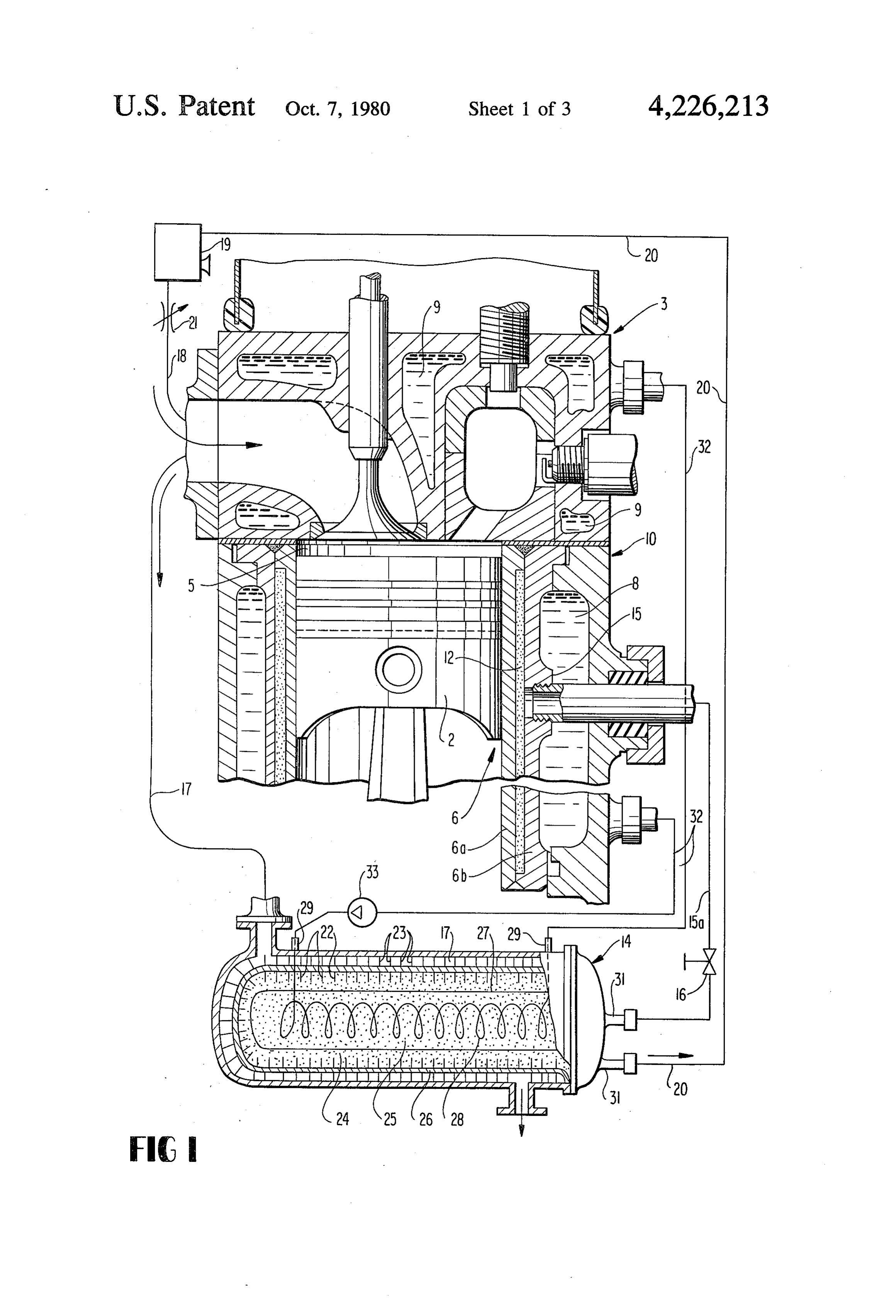
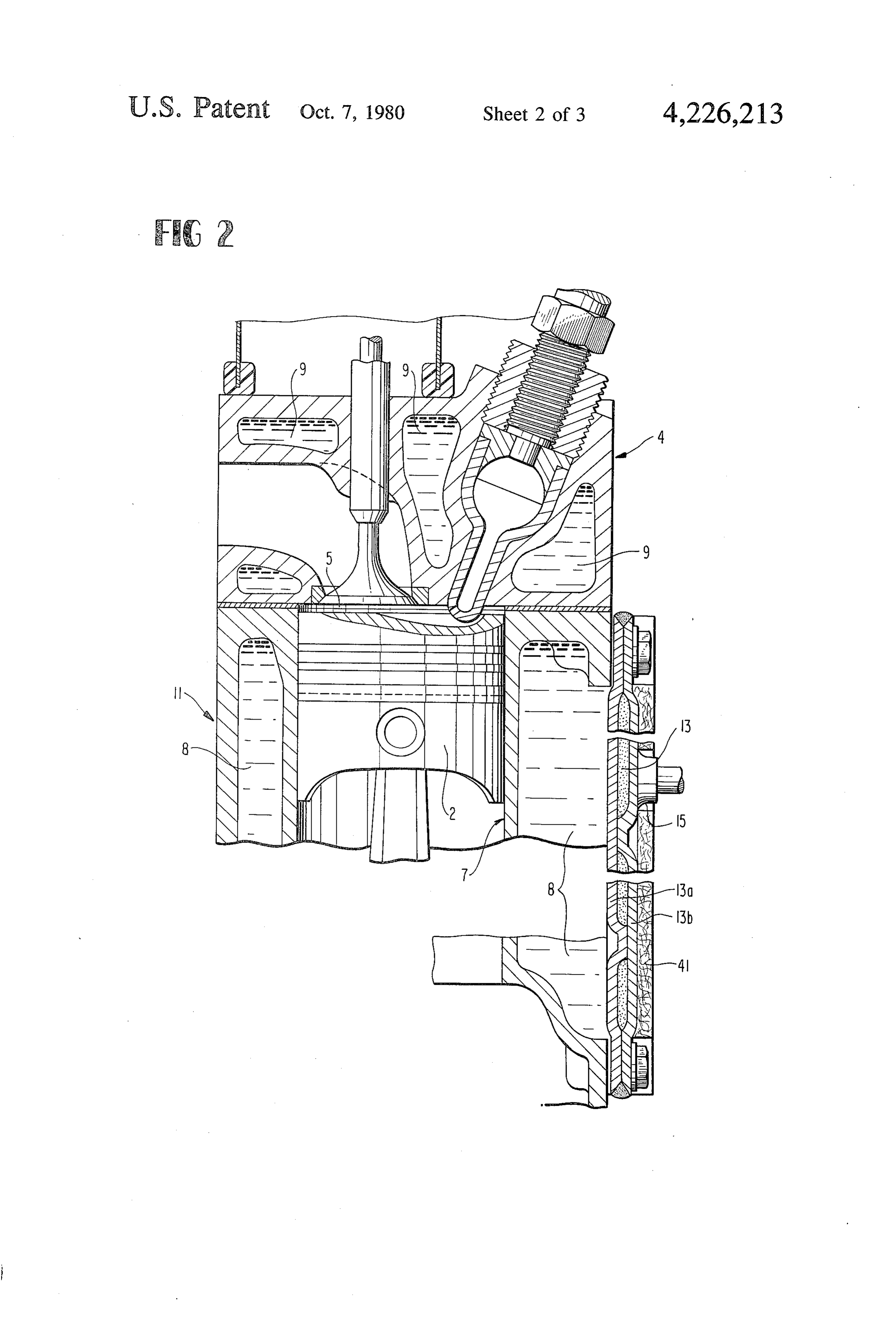
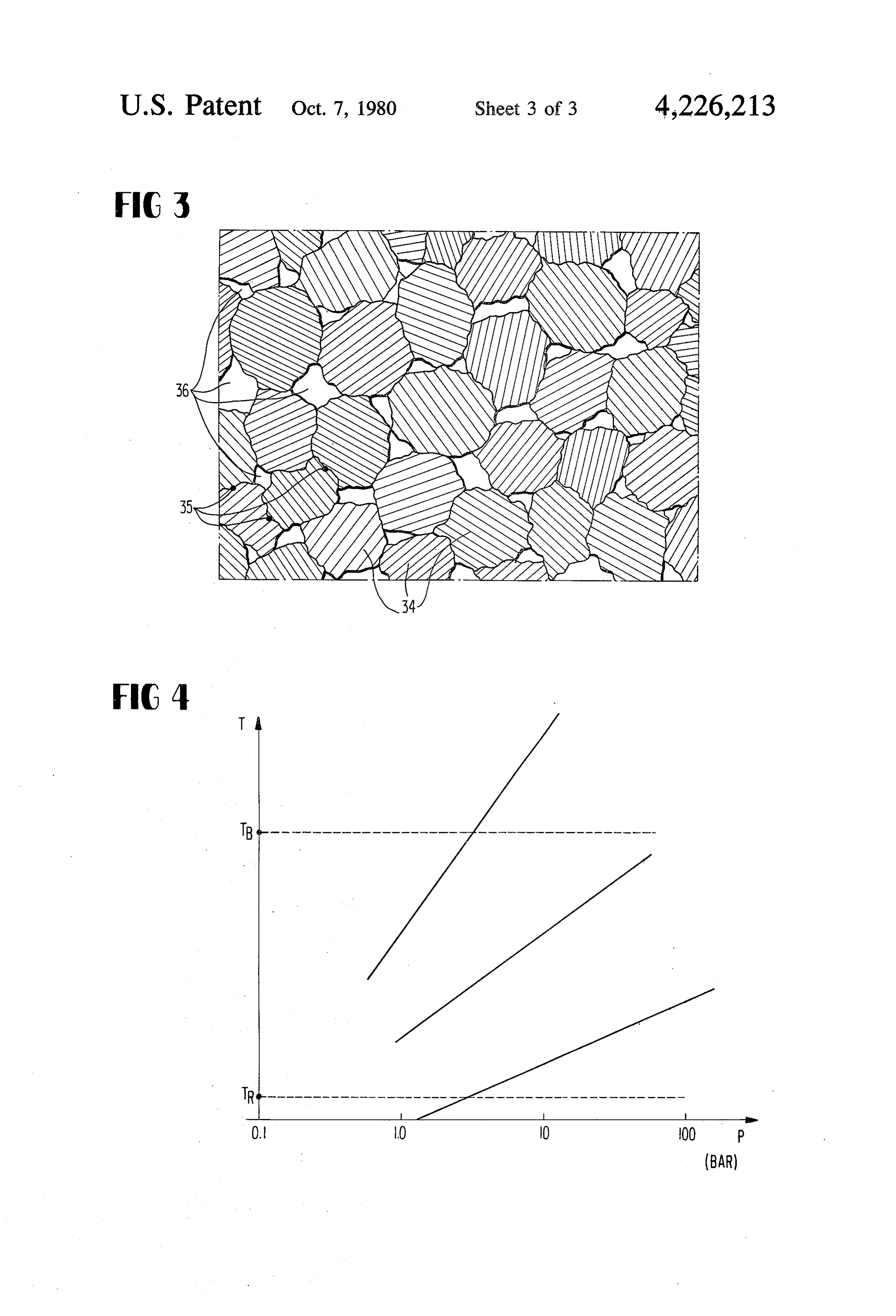
warm-up phase for the most varied reasons. In addition These and other objects, features and advantages of to many attempts for reducing the discharge of harmful the present invention will become more apparent from exhaust gas components, one also seeks to shorten the the following description when taken in connection warm-up phase of the engine. This, however, requires 15 with the accompanying drawing which shows, for pur either an increased energy expenditure or a construc poses of illustration only, two embodiments in accor tive, respectively, manufacturing expenditure which dance with the present invention, and wherein: can hardly be accepted, or also both together. FIG. 1 is a somewhat schematic cross-sectional view It is the aim of the present invention to provide a pre-heat astorage through part of an internal combustion engine with a device built into the cylinder liner as measure for the shortening of the warm-up phase of the 20 well as the operative connection of the pre-heat storage engine, in connection with which no additional energy device with a main storage device in accordance with is required and which is simple in construction. the present invention;
The underlying problems are solved according to the FIG. 2 is a partial cross-sectional view through a present invention in that a hydrogen-impervious, encap 25 modified embodiment of an internal combustion engine sulated metal hydride storage device is provided in with a pre-heat direct heat-conducting contact or indirectly by way of present invention.storage device in accordance with the a convective heat-exchanging connection with the FIG. 3 is a cross section, on an enlarged scale, walls and in that the interior of the encapsulation is through a sintered structure of the pre-heat storage adapted to be connected selectively to a hydrogen 30 device; and source and/or to a separate further hydrogen storage FIG. 4 is a diagram illustrating the pressure tempera device. ture curve of metal hydrides of different types. As known, certain metals, respectively, metal alloys Referring now to the drawing wherein like reference possess the property to absorb hydrogen into their crys numerals are used throughout the various views to talline structure and to thereby give off heat. With an 35 designate like parts, and more particularly to FIGS. 1 external heat supply and/or at low hydrogen pressures, and 2, in the two internal combustion engines illustrated these metals again release the hydrogen. It thereby in these two figures, a piston 2 is guided to reciprocate involves a completely reversible process which can be up and down in a cylinder liner generally designated by repeated as frequently as desired. For purposes of reference numeral 6 and 7, respectively. The engine warming-up the internal combustion engine prior to or 40 block generally designated by reference numerals 10 during the start, hydrogen is supplied to the pre-heat and 11, respectively, which belongs to the internal com storage device which absorbs the same within itself and bustion engine, is provided with a cylinder head gener is thereby heated up. The pre-heat storage device re ally designated by reference numerals 3 and 4, respec leases this heat at least indirectly to the combustion tively. The working space 5 is enclosed by th aforemen space walls. With an engine at warmed-up operating 45 tioned engine parts. The walls delimiting the working temperatures, the hydrogen bound during the starting space are cooled by a cooling water jacket 8, respec phase is again released out of the pre-heat storage de tively, by spaces 9 filled with cooling water in the cylin vice by the engine heat and is absorbed in a hydrogen der head 3, respectively, 4.
storage device taken along in the vehicle, whereby it is In the embodiment according to FIG. 1, a pre-heat then available again for a renewed cold starting opera 50 storage device 12 is provided in the cylinder liner 6. tion. Consequently, operating waste heat of the engine The latter is made for this purpose of two liners 6a and is temporarily stored hydrated, so to speak of, so that 6b which are welded together at their end faces in a the heat quantity necessary for the warm-up of the hydrogen-tight manner. A connection 15 for the supply, engine prior to or during the cold start takes place by respectively, discharge of hydrogen, is provided at the means of temporarily stored engine waste heat, i.e., 55 outer liner 6b. The pre-heat storage device 12 is opera energy-free. tively connected with a main storage device generally Accordingly, it is an object of the present invention designated by reference numeral 14 for hydrogen by to provide an internal combustion engine which avoids way of a line 15a and a closure valve 16. Hydrogen can by simple means the aforementioned shortcomings and be supplied from the main storage device 14 to the drawbacks encountered in the prior art. 60 pre-heat storage device 2 with an open valve 6 during Another object of the present invention resides in an the cold start phase or also before, so that the pre-heat internal combustion engine in which the exhaust of storage device 12 heats up and together therewith the harmful exhaust gas components is significantly re internal combustion engine is heated up rapidly. duced during cold starting. The metal hydride storage device A4 is illustrated in A further object of the present invention resides in an 65 detail in FIG. 1 in the form of one possible embodiment; internal combustion engine in which the warm-up phase a certain particularity of this storage device resides in of the engine can be considerably shortened by ex the fact that it can be supplied both with a liquid as also tremely simple means. with a gaseous heat-exchanging medium. A granulate
Page 6scan →
24 of a suitable metal hydride, respectively, metal or of about 1 Bar, temperatures above about 300° C. are metal alloy adapted to be hydrated is contained within necessary in that case for the far-reaching emptying of an inner pressure vessel 26 of a material that is diffusion the storage device. Such temperatures can be produced impervious with respect to hydrogen. An outer pres by means of the exhaust gases if the exhaust gas lines 17 sure vessel is placed about the inner pressure vessel 26 are heat-insulated.
while maintaining an intermediate space. Internal heat The operation of the pre-heat storage device is now exchanger ribs 22 provided on the inside of the vessel 26 briefly as follows:
protrude into the interior of the granulate 24, which Starting from a metallic condition of the pre-heat have the task to establish as good a heat-conducting storage device 12, the closure valve 16 in the hydrogen connection as possible between the interior container 10 line 15a is opened prior to or during the beginning of the wall and the granulate. Similarly, heat-exchanger ribs cold start, as a result of which, hydrogen can flow from 23 are provided on the outside of the inner container the main storage device 14 into the pre-heat storage which have the task to establish as good a heat-transfer device 12. If the temperature level of the metal hydride as possible from a gaseous medium flowing through the in both storage devices, namely, in the pre-heat storage intermediate space to the container wall. The engine 15 device 12 and in the main storage device 14, are equal, exhaust gas is conducted during engine operation then hydrogen will exist in the main storage device 14 at through the intermediate space formed between the two a higher pressure than in the pre-heat storage device 12 containers. A cooling coil 28 is embedded in the interior at the temperature prevailing in both storage devices at of the granulate 24 which is connected by way of the the beginning of the cold-starting operation by reason connections 29 with the cooling water circulatory sys of the larger storage capacity of the main storage device tem 32 of the engine equipped with a circulating pump and by reason of a minimum filling condition of the 33. The interior of the granulate 24 is reached by way of main storage device which can be assumed, so that a the cooling coil 28 whereas the outer zone of the granu certain dissociation pressure can be exerted from the late can be reached by way of the casing 26 and the ribs main storage device on the pre-heat storage device 22 provided thereon. Of the gas connections 31 25 which leads to a storage of hydrogen in the metal parts mounted in the cover flangedly fastened at its end face, of the pre-heat storage device. The latter thereby heats which are connected-eventually by a retention up very strongly and gives off its heat to the two liners sieve-with the hollow spaces of the granulate, one of 6a and 6b of the cylinder liner 6. This is true if the main the gas connections 31 leads to a mixture preparation storage device 14 is fully hydrated, i.e., if it possesses device 19 by way of the line 20. The internal combus 30 pressures of the order of magnitude of 50 Bar, whereas tion engine sucks in a hydrogen/air mixture from the the pre-heat storage device is non-hydrated. The capac mixture preparation device 19 by way of the throttle ity differences between the main storage device and the device 21 and the mixture suction line 18. This mixture pre-heat storage device (factor 100) assure that the pres may be enriched additionally with liquid fuel, for exam sure in the main storage device has not dropped consid ple, with gasoline during mixture operation of the inter 35 erably after the filling of the pre-heat storage device. It nal combustion engine by way of an injection valve in a is possible thereby to utilize the same hydride formers prechamber. A second one of the two connections 31 is for both storage devices. Of course, also metal hydrides connected with the preheat storage device 12, respec with different formation enthalpies can be utilized; tively, 13. whereby it is desirable to utilize a metal hydride in the For purposes of improved heat conduction inside of 40 pre-heat storage device which possesses a high forma the metal granulate, the latter may be sintered together tion enthalpy (higher temperature level and larger re or compressed form-stable. This is true both for the leased heat quantity), whence the heating up process main storage device 14 as also for the pre-heat storage can be accelerated. As a result of the heating up of the device 12, respectively, 13. It is appropriate if copper or storage device 12, the walls of the working space 5 are aluminum chips are also compressed together with the 45 warmed-up directly and after a certain length of time metal hydride or metal alloy hydride granulate. The also the cooling water of the engine. The warm-up copper or aluminum chips do not hydrate and retain phase is considerably shortened thereby. If the closure their good thermal properties also when the granules of valve 16 is intentionally opened two to three minutes the granulate material which are adapted to be hydrated prior to the starting of the internal combustion engine, are in fact hydrated. The pressed-in chips assure for a 50 then during the starting of the internal combustion en good heat flow in the compressed blank of metal hy gine, already a sufficiently preheated working space is dride granules which are themselves poorly heat-con present so that one can reckon with qualitatively better ducting in the hydrated condition. The pore proportion exhaust gases immediately from the start. in the granulate should amount to at least about 5% to If the internal combustion engine has reached its about 10% in order to provide still sufficient gas 55 operating temperature, then the drop of the dissociat exchange channels inside of the compressed blank or iion pressure reverses. With a strongly heated pre-heat sintered body. ing storage device, the hydrogen exists within the same The filling 25 of the inner metal hydride storage de at a higher pressure than in the main storage device 14. vice encapsulated by the wall 27 and penetrated by the The pre-heat storage device which has returned to the pipe coil consists of a low temperature metal hydride, 60 metallic dehydrated condition, represents in this condi for example, of titanium-iron-hydride, whereby with tion a charged heat storage device which is charged by the use of such filling material, the storage device is engine waste heat. It cannot lose its heat stored in chem adapted to be completely emptied of hydrogen at tem ically bound form by radiation or convection. At the peratures of -20°C, up to --80 C. (for example, cool latest, when turning off the internal combustion engine ing water) and at an excess pressure of 1 to 10 Bar. The 65 in its operationally warmed-up condition, the closure outer storage device 24 between the walls 27 and 26 valve 16 has to be closed in order that the metallic consists of a high temperature metal hydride, for exam condition of the pre-heat storage device remains pre ple, of a magnesium-nickel hydride; at excess pressures served up to the next cold-starting operation.
Page 7scan →
In the other embodiment of an internal combustion While I have shown and described only two embodi engine according to FIG. 2, the cylinder liner 7 illus ments in accordance with the present invention, it is trated therein is constructed in one piece with the asso understood that the same is not limited thereto but is ciated engine block 1. An outwardly disposed wall of susceptible of numerous changes and modifications as the cooling water jacket 8 at the engine block is con known to those skilled in the art, and I therefore do not structed as plate-shaped pre-heat storage device 13 hav wish to be limited to the details shown and described ing two sheet metal walls 13a and 13b held at a distance herein but intend to cover all such changes and modifi from one another. The two plates are welded together cations as are encompassed by the scope of the ap gas-tight along the outer edge; they are simultaneously pended claims.
held tension- and compression-resistant at a distance by 10 I claim:
pressed-in warp-like embossments. A connection i5 for 1. An internal combustion engine having cylinder the supply, respectively, discharge of hydrogen is also wall means adapted to be cooled and delimiting at least arranged on this pre-heat storage device 13 in the same one working space means of an internal combustion manner as shown in FIG. I. The walls delimiting the engine, characterized in that a hydrogen-impervious working space 5 of the internal combustion engine are 15 enclosed metal hydride storage means having an enclo heated up in this embodiment from the pre-heat storage sure means is provided in direct heat-conducting con device 13 by convective heat-exchange by way of the tact within the cylinder wall means forming a pre-heat cooling water. Even though the process of the pre-heat storage means, and in that an interior of the enclosure ing of the internal combustion engine possibly takes means of the metal hydride storage means is operable to somewhat longer than in the embodiment according to 20 be selectively connected with at least one of a hydrogen FIG. 1, the construction and arrangement of the pre source and a separate further hydrogen storage means. heat storage device 13 is somewhat simpler in compari 2. An internal combustion engine according to claim son to that of FIG. 1. In order that the pre-heat storage it, characterized in that the at least one of the hydrogen device gives off its heat to the cooling water of the cold source and further hydrogen storage means is con engine to a far-reachingly predominant extent, but not structed also as further metal hydride storage means. to the outside air, a heat-insulating layer 41 is provided 25 3. An internal combustion engine according to claim on the outside of the pre-heat storage device 13. If the 2, characterized in that the further metal hydride stor pre-heat storage device 13 is directly built into the cool age means is larger by a multiple than the pre-heat stor ing water, then the insulation with respect to the outside age means and in that both the pre-heat and further atmosphere may be dispensed with. The operation of metal hydride storage means are filled with metal hy the pre-heat storage device in the embodiment of FIG. 30 drides of about the same temperature level. 2 is completely analogous to that of the embodiment 4. An internal combustion engine according to claim according to FIG. 1 so that reference may be had to the 2, characterized in that the further metal hydride stor preceding description of the embodiment of FIG. 1. age means and the pre-heat storage means are dimen FIG. 3 illustrates on a strongly enlarged scale a por sioned approximately identical as regards the hydrogen tion of a cross section through a porous sintered layer as 35 storage capacity thereof and in that-under the assump is aimed at for the formation of the embedded layer. In tion of a certain substantially identical dissociation the structure of this layer, granules 34 are areally pressure-the temperature level of the pre-heat storage welded together at the initially loose contact places in means is higher by about 60' to 80° C. than that of the nearly molten condition under pressure and heat at further metal hydride storage means.
these places 35. Pores 36 remain between the granules, 5. An internal combustion engine according to claim which serve for the absorption of hydrogen in gaseous 4, characterized in that the engine is supplied at least condition and which serve for the distribution of the partially with hydrogen from the further metal hydride hydrogen inside of the sintered structure. By reason of storage means as fuel.
the melting of the granules in the sintered structure, the 6. An internal combustion engine according to claim same are connected with each other providing good 45 2, 3 or 4, characterized in that a check valve means thermal conduction. The sintered structure itself is, as a which is operable to be selectively opened and which whole, gap- and crack-free; the latter would prevent a closes in the direction toward the pre-heat storage good thermal conduction-in the metallic condition of means is arranged in a connecting line between the two the granules. A merging of the granules with the wall storage means.
material, i.e., a good thermal contact, also comes into 7. An internal combustion engine according to claim being at the contact places of the sintered structure with 50 2 or 3, characterized in that the engine is supplied at the adjoining hydrogen-impervious wall material. least partially with hydrogen from the further metal The basic configuration of the characteristic curves hydride storage means as fuel.
of different metals or metal alloys adapted to be hy 8. An internal combustion engine having an engine drated is plotted in the pressure/temperature diagram of 55 block means adapted to be cooled, said engine block FIG. 4. The configuration and position of these curves means comprising cylinder wall means delimiting at and of the metals coordinated thereto is known. One least one working space means of the internal combus may now pick for the selection of an embedded layer tion engine, and outwardly disposed wall means, said appearing suitable for the pre-heat storage device the cylinder wall means and said outwardly disposed wall two limit values for the space or cooling off tempera means delimiting a water jacket means, characterized in ture TR and the operating temperature TB in a diagram 60 that a hydrogen-impervious enclosed metal hydride containing the characteristic curves of the different storage means having an enclosure means is provided in metals along the temperature axis and to select a charac direct heat-conducting contact within at least a part of teristic curve, respectively, the corresponding material the outwardly disposed wall means, and in that an inte lying between these two values. High temperature hy rior of the enclosure means of the metal hydride storage drides are, for example, magnesium-nickel-hydride means is operable to be selectively connected with at (Mg2NiH4), magnesium or titanium hydride (MgH2, least one of a hydrogen source and a separate further TiH2). A low temperature hydride would be, for exam hydrogen storage means.
ple, titanium-iron-hydride. : se &
Provenance
- Collection
- Patents citing this work
- Pages
- 7
- Method
- pdftotext (the PDF's own text layer) + pdftoppm 300dpi page scans
- Patent office record
- patents.google.com →
- Source
- Google Patents citing-documents table
- Assignee
- Daimler-Benz Aktiengesellschaft
- Published
- 1980-10-07
- Transcribed from
- patentimages.storage.googleapis.com →