

patent · US4237867A
Solar energy collector
9 December 1980
Text
Page 1bibliographic recordscan →
United States Patent (19) 4,237,867 Bauer Dec. 9, 1980 (54) SOLAR ENERGY COLLECTOR 4,119,083 10/1978 Heyen et al.......................... 126/270 76 Inventor: William C. Bauer, 175 Cordova Ct. FOREIGN PATENT DOCUMENTS Boulder, Colo. 80303 2629086 l/1978 Fed. Rep. of Germany ........... 126/270 (21) Appl. No.: 920,490 Primary Examiner-Samuel Scott 22 Filed: Jun. 29, 1978 Assistant Examiner-Randall L. Green 51 Int. Cli................................................. F24J 3/02 (57) ABSTRACT 52 U.S. C. ..................................... 126/441; 126/449 Solar energy absorbing means in solar collectors are Field of Search ............... 126/270, 271, 449, 430, provided by matts of a fibrous material which by its
chemical composition absorbs solar radiation, convert (56) References Cited ing this energy to thermal energy within the fiber itself.
2,979,424 4/1961 Whitehurst et al. r. 350/96.10 X controlled by the state of oxidation and amounts of 2,998,005 8/1961 Johnston .............................. 126/270 various multivalent chemical components contained 3,815,574 6/1974 Gaydos, Jr. within the material composing the fibers. The thermal 3,875,925 4/1975 Johnston .... energy thus collected is transferred to a heat transfer 4,015,582 4/1977 Liu et al. ......................... medium by either passing the fluid directly through the 4,018,211 4/1977 Barr.................................. 126/271 X matt of fibers or through pipes or coils imbedded in the 4,038,969 8/1977 Smith ............................... 126/27 X matt.
4,078,548 3/1978 Kapany ................................ 126/271 4,082,082 4/1978 Harvey ....... 126/270 X 4,117,829 0/1978 Gross et al. .......................... 126/270 8 Claims, 3 Drawing Figures
SOAR ENERGY COLLECTOR
SOAR ENERGY
NFRARED PERMEABLE GAZING
AS RECURED
aer COO RETURN AIR
FBER GLASS
(5) Low RON 2ZZZZZZZZZZZZZZZZZZZZZ
(6) HIGH RON
FRP SHELL
-- HEATED AR
Drawings
Page 2drawing sheetscan →
Page 3drawing sheetscan →
Page 4drawing sheetscan →
Page 5scan →
the one or two panes of glass required to establish the
SOLAR ENERGY COLLECTOR "greenhouse' protection for the recovered heat must be of sufficient thickness, usually at least one-quarter of an
BACKGROUND OF THE INVENTION inch, to give the structural strength required to protect This invention resulted from an experimental pro the collector system from breakage. This adds consider gram to develop an extremely cheap yet lightweight able weight to the collector as well as a substantial Solar collector. Although many types of solar collectors increase in cost.
have been covered by patents, most of these are the Another disadvantage of the flat-plate collector sys so-called flat-plate collector which by its very nature O tem involves the various heat-absorbing coatings which has many disadvantages. It is the purpose of this inven must be carefully applied to the metal plate. These coat tion to overcome these disadvantages and at the same ings in turn may deteriorate with use, requiring disas time develop a collector which will be relatively low sembly of the unit for the necessary repair procedures. cost in materials and construction. It is thus obvious that the typical solar collectors avail able today are heavy, relatively costly, and subject to breakage.
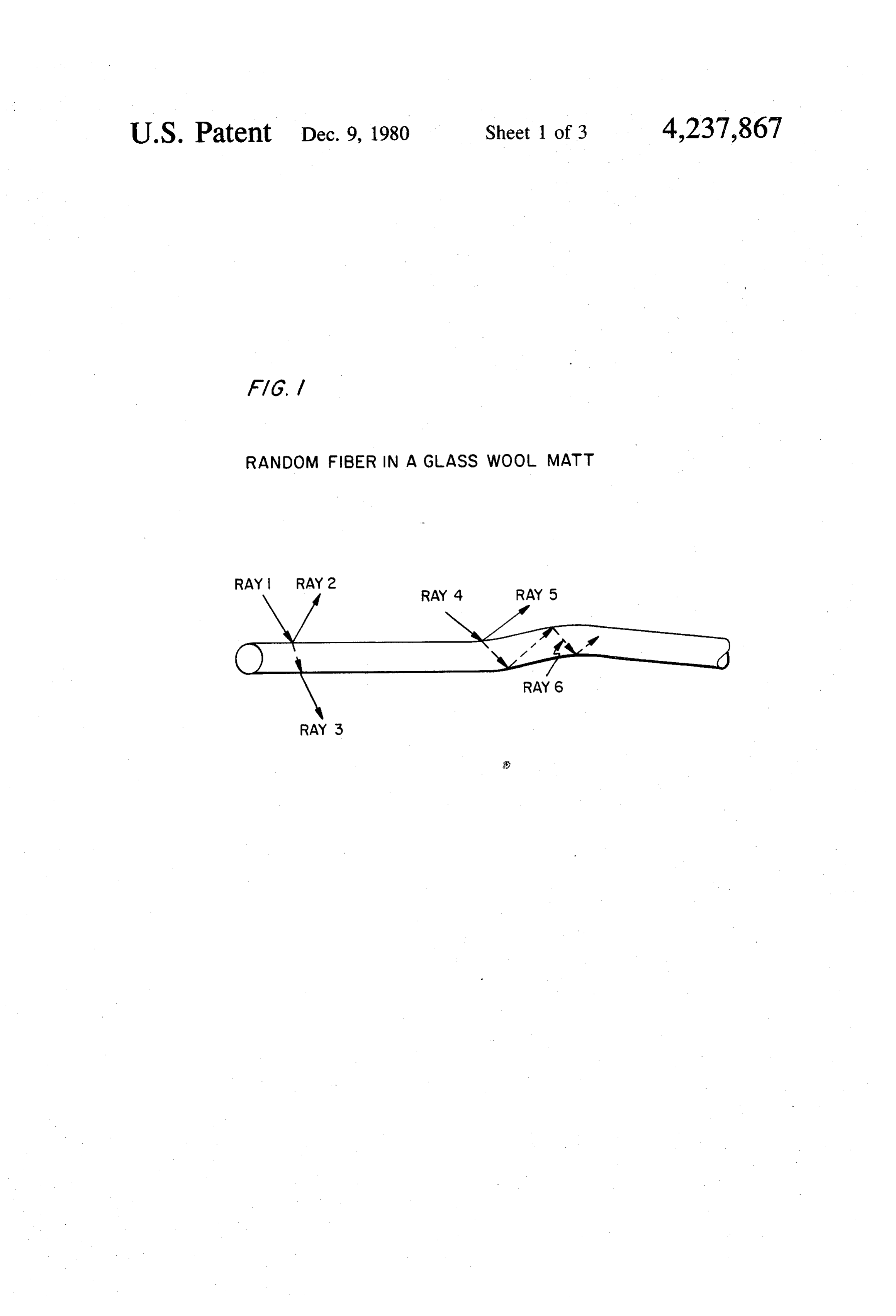
In general, the flat-plate solar collectors, which are BRIEF DESCRIPTION OF THE DRAWINGS by far the most common in commercial application at this time, utilize the same technical principles. The flat FIG. 1 illustrates the passage of lights rays 1-6 plate, usually of metal, typically copper or aluminum, is through a random fiber in the glass wool matt; while coated with a heat-absorbing material which converts 20
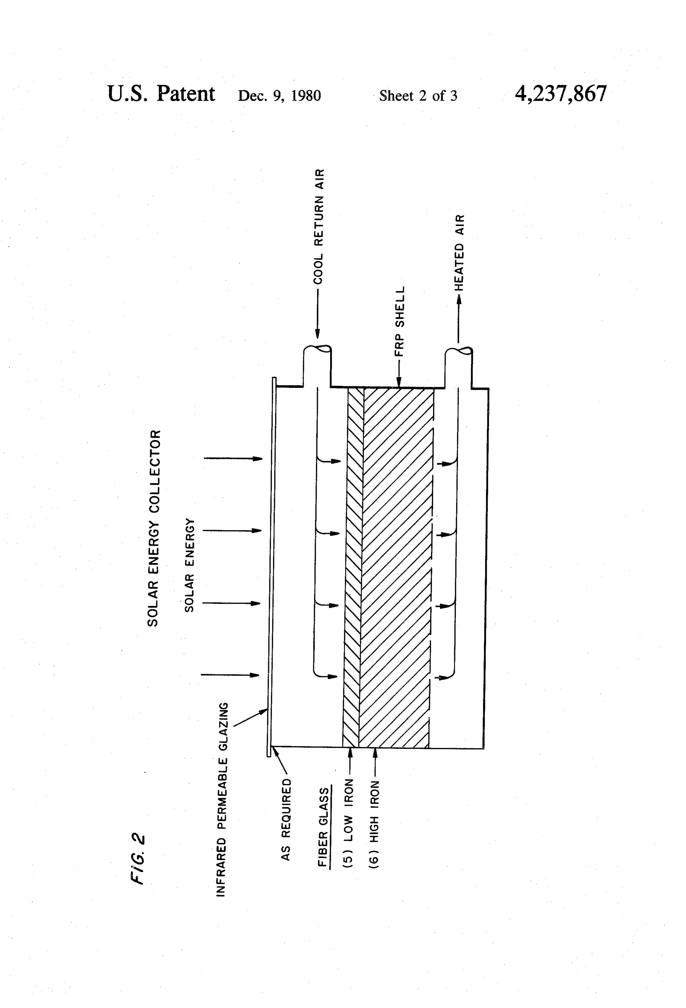
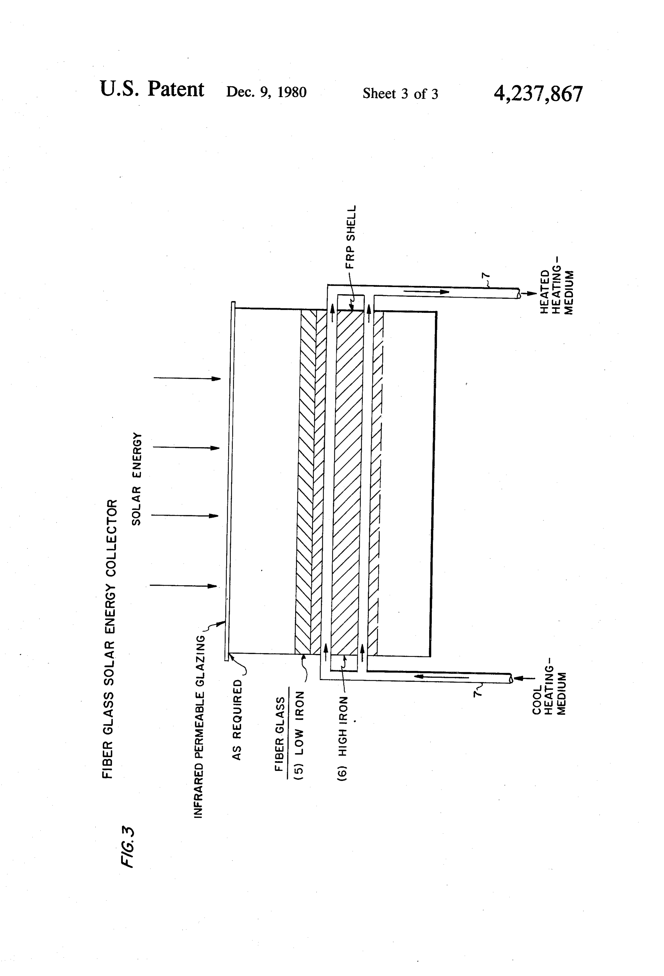
FIG. 2 illustrates one embodiment of the solar collec the energy in solar radiation into heat within the thin tor including a first layer of glass fiber (5), whose chem surface coating. This heat in turn is conducted through ical composition permits only minor attenuation of the the plate and transferred to the heat-collecting fluid solar energy rays that pass through these fibers, a sec which can be either a liquid or gas. By the very nature ond layer of glass fibers (6), whose chemical composi of heat transfer, it is obvious that the temperature of the 25 tion permits absorption and greater attenuation of solar collector surface must be somewhat greater than the energy into heat than the first layer, and openings for temperature attained by the heat-collecting fluid, typi admitting air into and out of the layers of glass fibers. cally in the range of 160-240 F. Although the wave lengths of the energy in the solar radiation striking the torFIG. 3 illustrates one embodiment of the solar collec collector surface are largely within the limits of the 30 including a first layer of glass fiber (5), whose chem visible spectrum (0.4-0.7 microns), the hot surface of ical composition permits only minor attentuation of the Solar energy rays that pass through these fibers, a sec the collector itself becomes a radiator of infra-red en ond layer of glass fibers (6), whose chemical composi ergy which in turn is reradiated back towards the tion permits absorption and greater attentuation of solar Source of the solar radiation. In order to contain this infra-red energy within the collector, it is necessary to 35 energy into heat than the first layer, and pipe (7) embed ded within the second layer of glass fibers (6), which include as part of the collector solar windows, typically pipe is made up of a heat-conducting material, through soda-lime glass, which are transparent to the visible which spectrum but tend to absorb the energy in the infrared for collection a heat-transfer medium (heating-medium) passes range. This is the well-known so-called "greenhouse of heat.
effect'. Since the reradiated infra-red energy is actually 40 DESCRIPTION OF THE INVENTION absorbed by the window glass, this glass must necessar ily increase in temperature, reradiating or reflecting a It is the purpose of this invention to overcome the portion of the acquired infra-red heat back into the disadvantages described previously for the common collector, although some of this absorbed energy is flat-plate solar collector available in the market-place transferred by conduction through the glass and is lost 45 today. In order to accomplish this, advantage is taken of by convection and radiation on the outer side. For this the physical and optical properties of fiberglass, typical reason, it has been common practice in the construction of that currently in use for insulation purposes. An of flat-plate solar collectors to use two panes of glass extremely low-cost lightweight collector system is thus separated by a confined air space, which serves as an possible. Considering first the optical properties of insulating layer to minimize the loss of the infra-red 50 glass, and fiberglass in particular, reference is made to energy which has been absorbed and converted to heat FIG. 1. In this case a single fiber of glass is depicted by the inner pane of glass. which is a part of a bundle of glass wool or batt. Since The necessity to use glasses which are not transparent this particular fiber is located somewhere below the to infra-red energy is in itself a disadvantage, since the surface of the wool matt, it is assumed that rays of solar entire available energy of the incident solar radiation 55 light are striking the fiber at many random angles, since includes a substantial amount in the infra-red range they have previously been reflected, refracted and oth (wave lengths greater than 0.7 microns) which is then erwise bent in their travel through the overlying layers shielded from passing through the glass to the collector of glass fiber. In the case of Ray 1, which strikes the surface. Thus, when glass is used as the "greenhouse' fiber at a steep angle approaching 90°, some of the ray protection against reradiation, a portion of the solar 60 will be reflected back, as is indicated by Ray 2. Some of energy which is available for conversion to useful heat the light energy will pass directly through the fiber and is not allowed to enter the collector and is thus not be emitted through the far side as Ray 3. Because of the available for conversion to thermal energy. random angles at which the rays of sunlight are striking An additional disadvantage of the conventional solar at various fibers, it is assumed that some rays, such as collectors is the weight and cost of the unit. The collec 65 Ray 4 will strike the fiber at a sufficiently low angle that tor plates must be of some suitable metal which will the proportion not reflected (Ray 5) will, upon entering allow transfer of the heat from converted solar energy the fiber, be trapped within it (Ray 6) because of the to the collecting fluid utilized in the system. In addition, critical refractive angle phenomenon, and will continue 6 to pass down the length of the fiber. It is this very phe wool also has the advantages over the flat-plate collec nomenon that is currently being utilized in the develop tor. Because of the small fiber diameter and loose pack ment of fiber optics for the transmission of telephonic ing in glass wool, a tremendous surface area is exposed. and other electronic signals which have been modulated For example, in the case of typical glass wool-type upon a ray of light and directed into a glass fiber. In the insulation, there is over 72 square feet of fiber surface case of fiber optics, however, it is desired that the chem area per inch of wool in one square foot of cross-sec ical composition of the glass be of such high purity that tion. Thus, when a fluid passes through the wool, the there is a minimum tendency for attenuation of the contact between the wool and the fluid is extremely energy in the light beam in order that it will pass intimate and heat transfer occurs very rapidly. In addi through a substantial length of the fiber before being 10 tion, because of the loose packing in glass wool, which reduced to a negligible energy state. In contrast, in this often runs no more than 0.5 lbs per cubic foot in bulk invention it is desired that the purity of the glass be density, the energy required to force the fluid (pressure such, particularly in reference to the presence of multi drop) through the wool is extremely low. Again in the valent metallic ions, such as iron, chromium, nickel, general case, with air passing through three inches of cobalt, manganese and the like, that in a very short 15 typical glass wool insulation, the pressure drop for a gas length of fiber the solar energy contained in the trapped rate of 1 cu ft/min/sq ft is approximately 0.01 inches of beam of light will be absorbed and converted to heat Water.
energy by the attenuation of the light beam resulting In terms of cost, glass wool is considerably cheaper from the presence of the metallic ions. For example, in than the materials and production costs required to a typical type of amber glass conventionally used for manufacture typical flat-plate collectors. Current costs malt beverage containers, a ray of light in the visible for fiberglass insulation amount to only a few cents per spectrum will lose 99% of its energy, that is, 99% of the square foot for insulation 3 inches in thickness. In addi light energy will be converted to thermal energy by tion because of the lower cost for the plastic glazing raising the temperature of the fiber, after passing which would be satisfactory in this application, the total through a total path length of the amber glass of about 25 cost per module for solar collectors embodying the 3 centimeters. In short, it is the purpose of this invention teachings of this invention would be relatively low to utilize glass fibers of such chemical composition that compared with the conventional flat-plate units now solar energy contained in the rays of sunlight will be currently in use. In order to maintain both the low cost converted to heat energy after passing through a prede and lightweight advantages of this invention, it is fur termined length of fiber. ther recommended that the housings which make up the The second important principle embodied in this module and furnish the needed structural support be application of glass fibers for the collection and conver fabricated from fiberglass reinforced plastic (FRP) con sion of solar energy is illustrated in FIG. 2. As the figure struction. The additional external insulation required to illustrates, the uppermost layers of glass fibers (5) ex minimize heat losses from the heat transfer fluid would posed to the direct incidence of the rays of solar energy, 35 presumably be essentially the same regardless of the are intended to be of glass of chemical composition such type of collector module utilized. that only minor attenuation of the solar energy occurs It is not to be construed by this discussion that exist as this light passes through the upper layers of the glass ing fiberglass types of insulation are satisfactory for this matt. As the figure indicates, the layer of glass wool or application. In general they are not, and it would be other similar fibrous material designated as 6, is in 40 necessary to produce glasses meeting the special heat tended to be of such chemical composition that the absorption requirements for each layer of the solar col absorption and conversion of solar energy to heat oc lector in order to maximize the advantages possible by curs fairly rapidly. The purpose of the relatively trans the use of the glass fibers. Depending upon the particu parent overlay layer (5) is to serve as an insulating layer lar applications required for the various types of solar which will not particularly rise in temperature above 45 collectors utilizing the teachings of this invention, the. the ambient or temperature of the incoming heat-trans composition of the glass fibers in terms of the multi fer fluid, be it air or liquid. By this technique then, the valent metallic ions which cause the attenuation of solar layer of glass wool which "sees' the incoming source of light and its conversion to heat, various types of glass solar energy is at a relatively low temperature, and thus fibers would need to be produced to meet these various the tendency to reradiate infra-red energy as generated 50 requirements. This is, however, no problem since these by the higher temperatures in the bed will be greatly various compositions are common knowledge to glass reduced compared with flat-plate collectors. Thus the technologists and could be easily manufactured. The uppermost layer of wool isolates (and insulates) the components required are readily available and, in fact, layers of glass in which the major portion of the heat is are commonly used in the production of other types of being generated, and, consequently, the need for the 55 glass. For the outside layer of wool which is primarily “greenhouse effect' as is required with the conven for the purpose of transmitting most of the solar energy tional flat-plate collector is much less important. This through to the inner layers of heat-absorbing fibers, has several advantages. First, it is not necessary to use glass compositions more or less typical of that currently thick and/or double layers of heavy, expensive window used in flint glass for containers would be satisfactory. glass to create the "greenhouse' protection, but rather 60 For example, using iron as the multivalent metallic it is possible to use cheaper and lighter-weight plastic additive, in general terms the iron contents would be of material. In addition it is desirable that these plastic the order of 0.03-0.06% expressed as Fe2O3. The glass materials be of the variety that will transmit as much as wools prepared for the function of converting the solar possible of the infra-red portion of the solar spectrum, energy to heat would vary over ranges, for example of since this too, is available for conversion to heat when 65 iron from 0.07 to 1.0% or higher. In addition, the state the protection from reradiation is not required. of oxidation of the iron is also involved in the absorptiv In terms of heat transfer from the heated collector ity of the glass for solar radiation and this too would be medium to the heat transfer fluid, the use of fiberglass regulated by the addition of typical reducing agents 7 now used in the preparation of all types of glass, to that in all cases of record the glass fibers serve merely as establish the optimum conditions for the specific appli a substrate for a blackened coating, and in fact the use of cations. Although the other metallic ions mentioned other fibrous materials such as steel wool, excelsior previously could and would be useful in this applica (wood), and the like, all coated with a black heat tion, the concentrations required would be in the same absorbing layer are similarly described. In no case has limits (0.05-1.0%, calculated as the highest oxide state the glass wool been suggested as a solar collector based of the metal) and the state of oxidation to develop the upon the optical properties of the glass itself as a trans optimum solar conversion properties of the glass would ducer of solar energy to thermal energy as is the subject be controlled as is now the case in glass manufacture by of this invention.
the addition of various oxidizing agents (sodium sulfate, 10 EXPERIMENTAL sodium nitrate, arsenic oxides, etc.) and reducing agents (sulphur, carbon, iron pyrite, and the like). Each spe In order to establish the validity of the principles cific application of this proposed collector would re covered by this invention, samples of commercially quire its own optimum compositions and thicknesses of available glass wool insulation have been subjected to the various glass wools involved, but it is to be under 15 test procedures. In these, wool batts several inches in stood that the production of these is simple and in effect thickness were exposed to direct sunlight with indicat is possible based upon present-day glass manufacturing ing thermometers located at various known positions procedures. below the top surface of the wool. The temperatures A similar principle of solar heat retention, although in were recorded as a function of the time of exposure. another medium is practiced in Israel. In these a basin is 20 Results typical of those which were obtained are pres filled progressively with brines of differing salt concen ented in the table below.
trations, thus establishing concentration layers along a vertical profile. Consequently, convection currents can not circulate through the entire depth of the pond. Glass Wool Temperatures - F. Rather, heat transfer between layers can occur only by 25 Sun Exposure Distance Below Top Wool Surface - Inches conduction. Sunlight incident on the pond for the most Time - Min. 1 2 3" 4' part passes through the upper brine layers to a black 0 Min. 75° F 75° F 75° F 75° F. ened bottom. The heat absorbed there conducts to the 2 97 88 78 75 lowest brine layer where it is effectively trapped by the 4.6 20 slow rate of heat transfer between layers. Temperatures 10 near the boiling point of water can thus be obtained. At 15 189 167 115 95 the same time, the high temperature zones in the solar 2540 205 188 29 106 collector are well-protected from infra-red reradiation 213 198 139 116 back into space by the various layers of brine which are transparent to the solar energy contained in the visible 35 It is apparent that temperatures in excess of 200 F. wave lengths, but are opaque to the wave lengths in the were readily obtained. When this wool was incorpo infra-red region. rated in a solar collector module similar to that illus It should also be noted that the use of packed-bed trated in FIG. 2, and ambient air at a rate of about 1 cu collectors has been reported in the literature (Swartman ft/min/sq ft of exposed area was passed over and down and Ogunlade, Solar Energy, 10, 1966, pp 106-110). In through the wool, an average exit temperature of the this case, the packed beds were composed of such mate heated air of 160' F. was obtained.
rials as copper screens, glass marbles, stones, and hol As an example of a glass wool which is relatively low celluloid spheres. Although interesting results were transparent to solar radiation, tests were made of a thin reported from the various tests performed in accor felt-like material commonly referred to in the trade as dance with this study, commercialization of the idea has 45 “veil'. This product is about 0.31 mm in thickness and not materialized, since the collection efficiencies were has a bulk density of approximately 2.7 lbs/cu ft. In not particularly superior to those obtained with flat order to establish the efficiency of this wool for absorb plate collectors, and because the cost and weight of the ing solar radiation a Dodge Solar Meter (Model 776) collectors containing such packings as stones and glass was employed to measure the incident solar energy marbles were of no advantage as far as making possible 50 level. Meter readings were taken with increasing num collectors lighter in weight and cheaper than those of bers of layers of the wool. The following results were the normal flat-plate variety. obtained:
The use of permeable collector media has also been reported (Chiou, El-Wakil and Duffie, Solar Energy, 9, 1965, pp 73-80). In this case packings are made from 55 Meter Readings such materials as slit-and-expanded aluminum foil Wool - Bu/ht/sq ft - blackened on one side, which was turned toward the Thickness Input Output sun. The solar collector was built up from several layers C Io It I/Io of the specially-prepared foils and the performance of O 312 312 l them as solar collectors was found to be reasonably 60 0.062 efficient. However, because of the costs involved in 0.186 30 150 0.0484 preparing the special packings and the necessity for a 0.248 310 128 0.43 blackened heat-absorbing layer on the collectors, these 0.31 30 102 0.329 too have not proved to be competitive with the flat-bed 0.372 collector. 65
It should also be recorded that the use of glass wool 1,12 305 7 0.023 has also been suggested and employed in various types of solar collectors. It should be pointed out, however,
Page 8scan →
In order to interpret these data the absorption proper the fiber glass, preferrably at the zones of maximum ties of this wool were characterized by calculating the temperature development, through which heat transfer absorption coefficient as is defined by the well-kown fluids can be passed to extract the available heat. In Lambert equation. addition, although glass fibers have been described as the basis for this invention, it is also obvious that fibers of other materials, such as plastics, slags, mineral wools, where Io=the intensity of the incident radiation etc., which have similar optical properties for trapping and converting solar energy rays and converting this
It = the intensity of the radiation after passing through energy to heat, would be equally applicable in the prac t=thickness or length of path through the absorbing ticeWhile of this invention.
certain advantages have been described which medium, cm a=absorption coefficient illustrate the merits of this invention, it is to be under In this case the absorption coefficient, a, is a definite stood that various changes and modifications can be property of the material and its value depends upon the 15 made by those skilled in the art without departing from chemical and physical properties of the wool. When log appendedthe scope and intent of the invention as defined in the (I/I) is plotted against the wool thickness, t, a straight claims.
line is obtained which has a slope equivalent to the What is claimed is:
absorption coefficient, a. In this case the absorption 1. In a solar collector comprising in combination a coefficient was found to have a numerical value of 3.35 20 collector housing, first means for absorbing solar en cm-l. ergy from incident solar radiation, second means lo Thus, it is apparent that the Lambert relationship can cated adjacent to the outer surface of said first means to be used to establish an equivalent absorption coefficient serve as a heat insulator, and fluid means for flowing for a fibrous wool material. Once this value has been through said first means to transfer heat from said first established for any given wool, the equation can then be 25 means to said fluid means, wherein said first means is a used to calculate the thickness of wool needed to obtain batt of fibrous material whose chemical composition any desired degree of attenuation in the intensity of the yields optical properties that permit solar rays that enter incident radiation. the fibrous material to be absorbed and converted to As has been explained previously, the types of glass thermal energy and said second means serving as a heat wool currently available for insulation purposes are not 30 insulator being a batt of fibrous material whose chemi necessarily those with the optimum optical properties cal composition yields optical properties such that for converting solar energy to thermal energy accord greater transmission and less attenuation of the solar ing to the teachings of this invention. Glass wools much energy occurs in this fibrous material of the solar rays more suitable for this application must be prepared passing therethrough than in the first means. specifically in terms of the amount and valence state of 35 2. The solar collector in claim 1 in which the optical the multivalent metallic ions contained therein. In par properties of the fibers to absorb or transmit solar radia ticular, a wool low in heat-absorbing components, such tion in said first and second means are determined by as iron, must be available which can serve as the top the content and valence state of the multivalent metallic layer as is indicated in FIG. 2, in which only a small oxides contained therein.
portion of the incident solar energy is converted to heat, but which will by its relative transparency allow the of3.multivalent
The solar collector in claim 2 in which the content major portion of the solar energy to be transferred to the fibers of saidmetallic components contained within first means varies within the range of the lower layers of wool where this conversion does 0.07 to 1.0 weight percent.
take place. In this manner the higher temperature zones 4. The solar collector in claim 1 in which the thermal in the wool are shielded from reradiation by the more 45 energy resulting from the absorption of the solar radia light-transparent and thus cooler upper layer. It is this principle that is a key factor in this invention. tion is transferred to the heat transfer fluid by direct Although glass wools containing various contents of passage of the fluid through the fibrous batts. 5. The solar collector in claim 1 in which the thermal the suitable multivalent metallic compounds as indi energy resulting from the absorption of the solar radia cated are suitable and desirable, it is not to be construed SO that these are the only combinations which will satisfy tion is transferred to a heat transfer medium which is the principles of this invention. It should also be under circulated through coils of a heat-conducting material stood that any suitable heat transfer fluid is applicable in imbedded within the first batt of fibrous material. the pursuit of this invention. This includes air, water, 6. The solar collector in claim 1 in which the batts of and other liquids which are common in current solar 55 fibrous material are composed of a glassy material. collector technology. The purpose of the glass wool is 7. The solar collector in claim 2 in which the content to convert the solar energy to thermal energy in a man of multivalent metallic ions contained within the fibers ner in which reradiation is minimized and the thermal of said second means varies within the range of energy is then transferred to a working fluid for the 0.03–0.06 weight percent.
normal purposes intended. Auxiliary additions to these 8. The solar collector in claim 1 wherein an infrared systems, such as heat storage units and other mechanical permeable glazing material is located on said housing and physical devices to control the flow of the heat above and remote from the first and second means and transfer fluids commonly used with other solar collec provides a space through which the heat transfer fluid tors, are certainly equally applicable in use with this flows between the second means and the glazing mate invention. It should also be understood that suitable 65 rial.
coils of pipe can be imbedded at appropriate locations in : : t sk
Provenance
- Collection
- Patents citing this work
- Pages
- 8
- Method
- pdftotext (the PDF's own text layer) + pdftoppm 300dpi page scans
- Patent office record
- patents.google.com →
- Source
- Google Patents citing-documents table
- Assignee
- Bauer William C
- Published
- 1980-12-09
- Transcribed from
- patentimages.storage.googleapis.com →