

patent · US4258701A
Solar collector panel
31 March 1981
Text
Page 1bibliographic recordscan →
United States Patent (19)
Buckley
(54) SOLAR COLLECTOR PANEL
Inventor: Bruce S. Buckley, Cambridge, Mass.
Assignee: Chevron Research Company, San
Francisco, Calif.
int. Cl. ................................................. F24J 3/02 52 U.S. Cl. .................................... 126/434; 126/446;
1,853,480 4/1932. Wheeler et al. ..................... 126/271 2,213,894 9/1940 Barry .................................... 126/271 2,388,940 1 1/1945 Taylor .................................. 126/271 2,705,948 4/1955 Rostock ... ... 126/271 3,463,161 8/1969 Andrassy ..... 126/400X 3,720, 198 3/1973 Laing et al. .......................... 126/400 3,785,365 1/1974 Laing et al. .......................... 126/408 3,980,071 9/1976 Barber, Jr. ........................... 126/271
4,003,367 1/1977 Wikholm .............................. 126/271 4,033,325 7/1977 Walker ... ... 126/271 4,050,508 9/1977 Buckley ................................. 165/32 4,073,284 2/1978 Laing ......... ... 26/400
4,095,585 6/1978 Oquidam .............................. 126/400 4,124,018 11/1978 Murray et al. ....................... 126/271
OTHER PUBLICATIONS
"Thermic Controls to Regulate Solar Heat Flux into
Buildings' Buckley, NSF Report NSF/Rann/Se/GI
Primary Examiner-James C. Yeung
Assistant Examiner-Larry Jones
Attorney, Agent, or Firm-Edward J. Keeling; R. H.
Evans
A heat transmission module wherein a natural-circula tion, solar collector, storage tank, insulation and other interrelated parts are fabricated as a unitary structure capable of bearing a load.
14 Claims, 15 Drawing Figures
Drawings
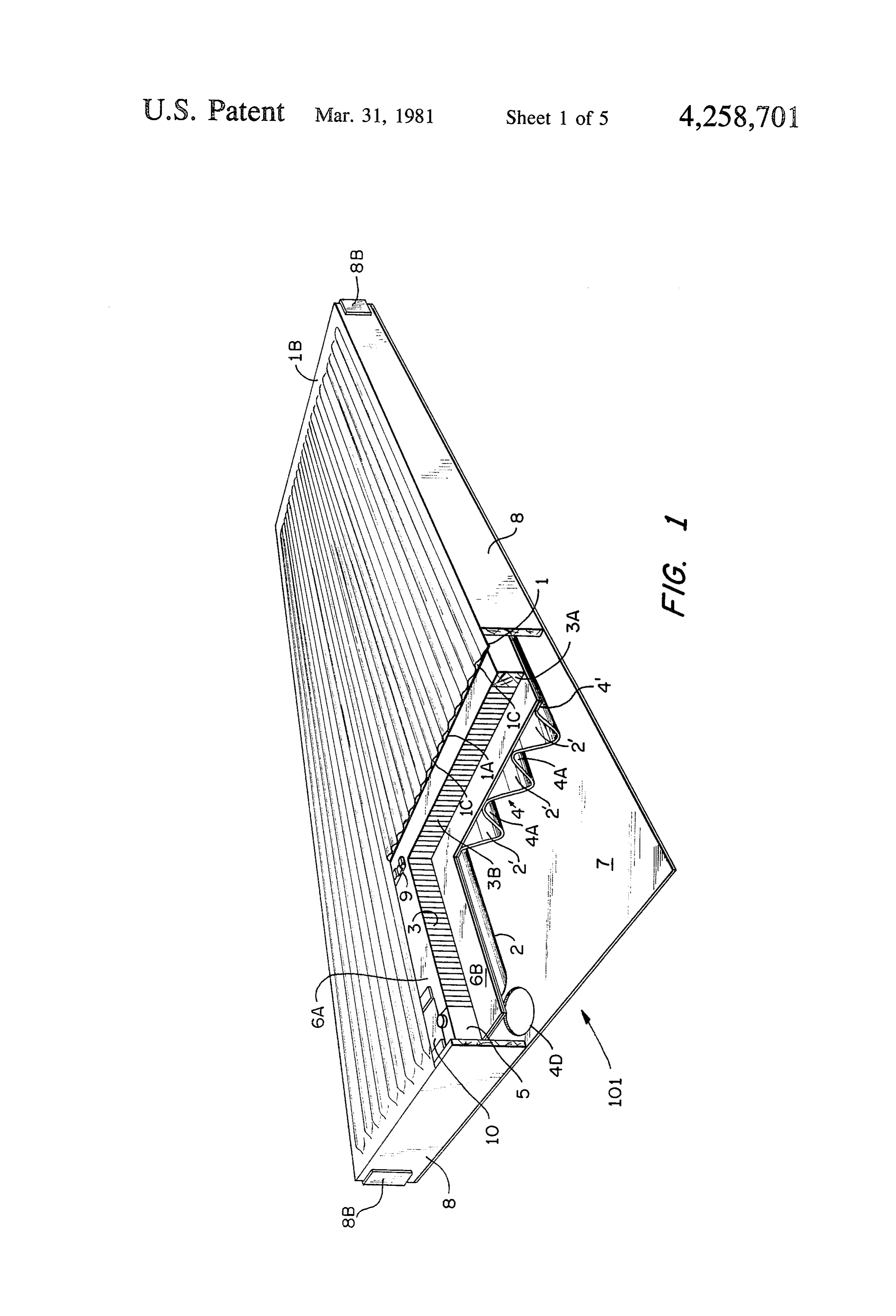
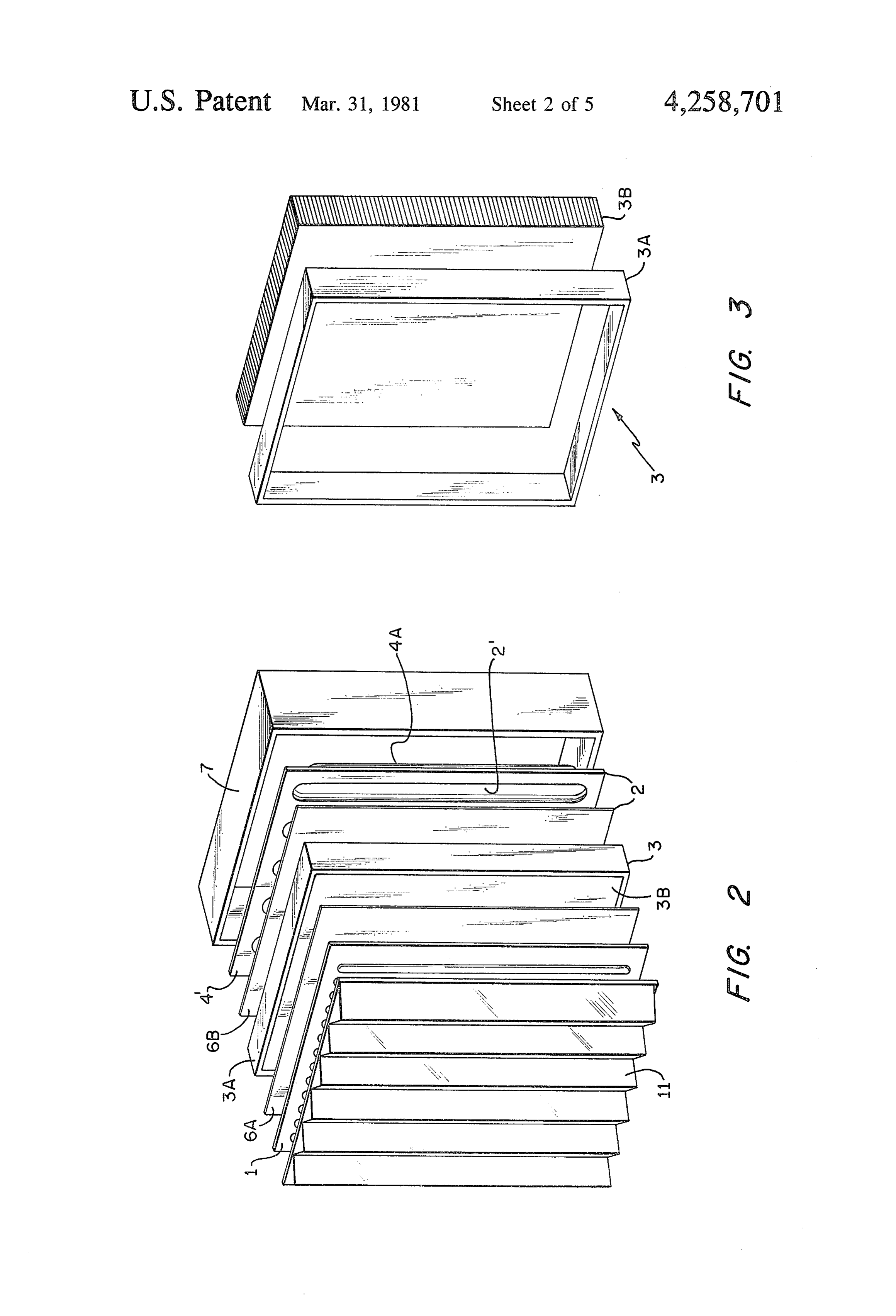
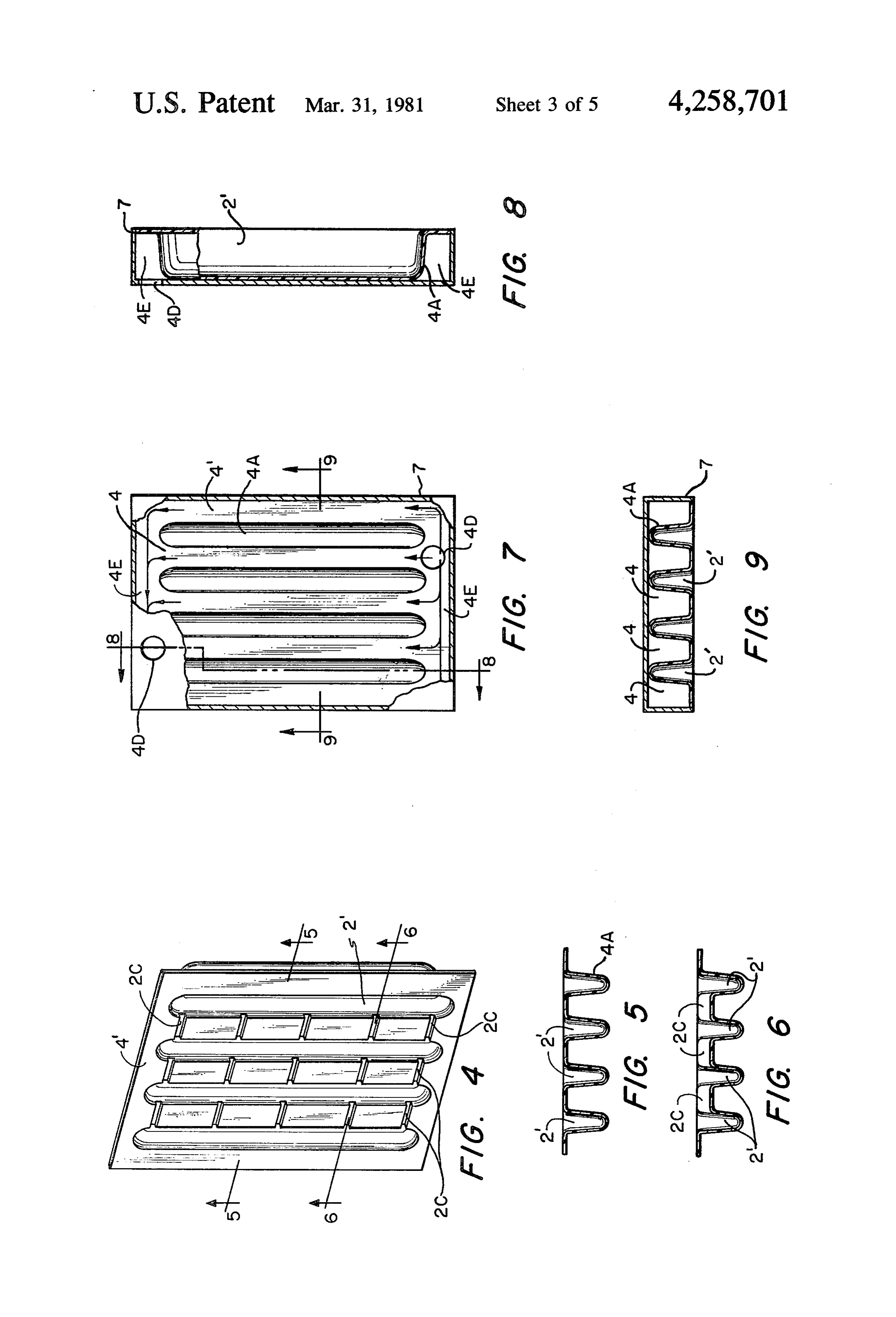
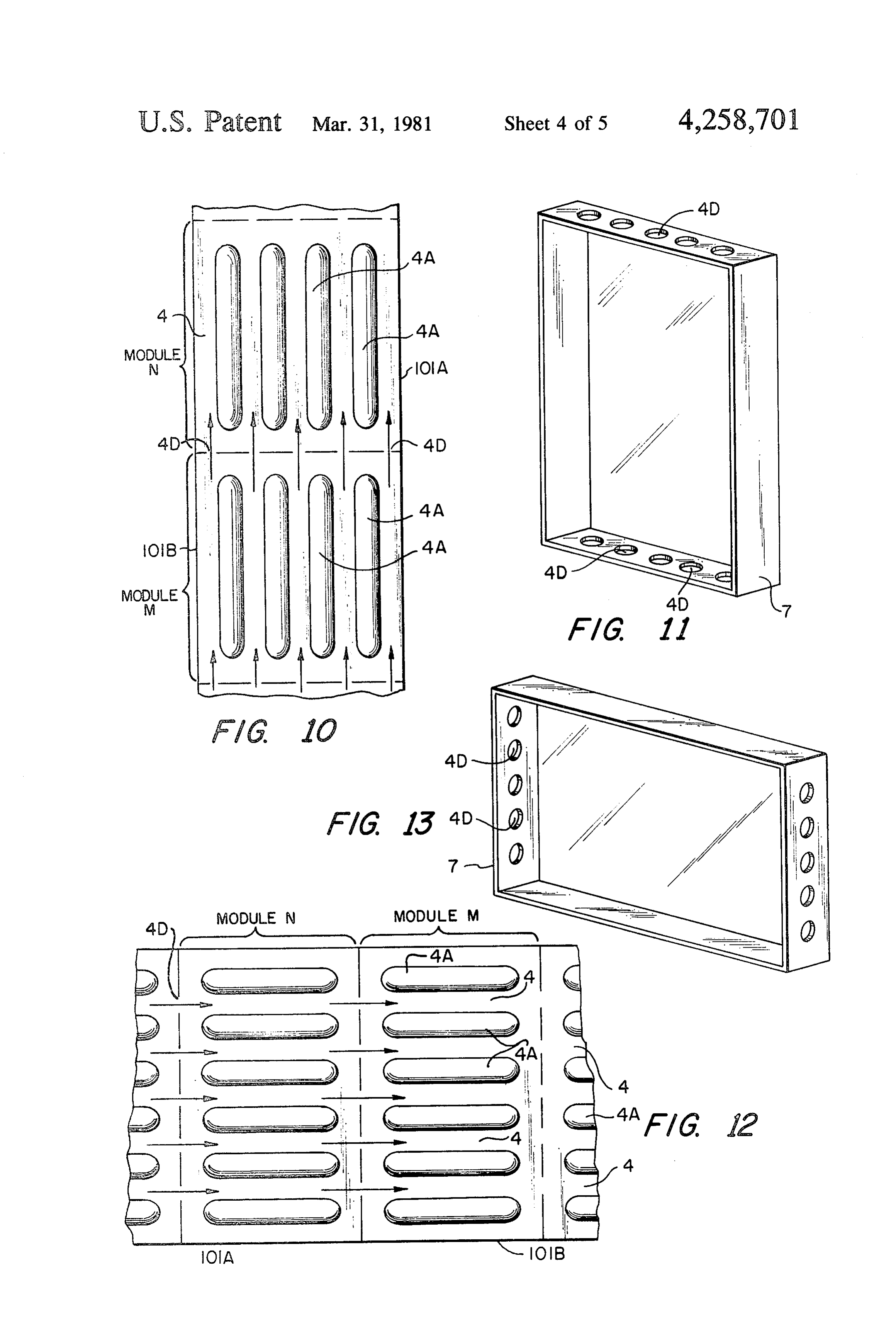
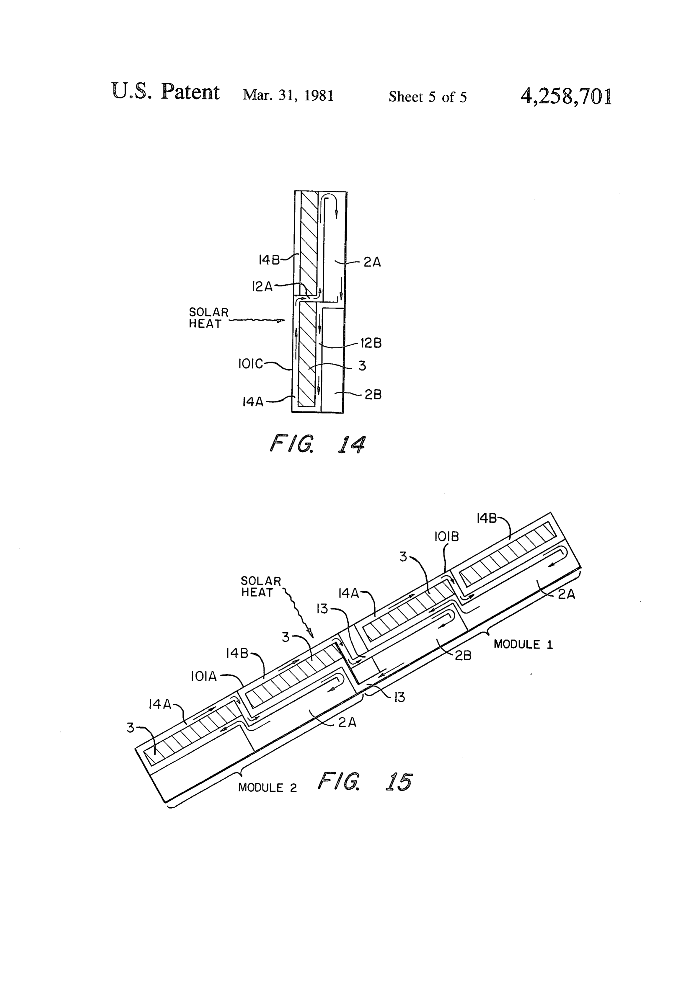
FIG. 10 is a schematic representation showing a part
Page 2drawing sheetscan →
Page 3drawing sheetscan →
Page 4drawing sheetscan →
Page 5drawing sheetscan →
Page 6drawing sheetscan →
Page 7scan →
FIG. 10 is a schematic representation showing a part
SOLAR COLLECTOR PANEL of two vertically oriented modules like the module of
GOVERNMENT RIGHTS FIG. 11 is an isometric view of a cover shell for each The Government of the United States of America has of the modules of FIG. 10;
rights in this invention under an agreement that is based FIG. 12 shows schematically an array like that of on National Science Foundation Grant No. GI-43897 to FIG. 10, but horizontally oriented; FIG. 13 is an isometric view of a cover shell for each the Massachusetts Institute of Technology. of the modules of FIG. 12;
The present invention relates to solar collectors and O FIG. 14 is a schematic section view of a modification the like.
Attention is called to an application for Letter Patent, of the module of FIG. 1; and
Ser. No. 588,093, filed June 18, 1975, now U.S. Pat. No. FIG. 15 is a schematic section view further showing 4,137,964, by the present inventor. two of the modules of FIG. 14 connected together. Solar energy collection systems usually have many 15 transmissionnow
Turning to FIG. 1 there is shown at 10i a heat module or panel that includes a solar col components which are distributed throughout a resi lector 1 consisting of an expansion membrane 1A and a dence: a collector on the roof, storage in the basement, sensor skin 1B that form a plurality of channels 1C to and so forth. However, these elements can be combined contain a liquid and allow the liquid to be heated by the together to form an integral module which has insulat sun's rays. Storage means 2, comprising a plurality of ing and structural properties as well. Combining these 20 elongated cells, is connected to exchange liquid with components together reduces both the material cost of the solar collector 1, there being liquid flow between the system (since one wall of storage can double as a the solar collector 1 and the storage cells 2" via natural wall of the insulation) and reduces installation cost convection circulation. An insulator 3 separates the through the use of an easily installed module. solar collector 1 from the storage means 2. As later Accordingly, an object of the present invention is to 25 discussed herein, the solar collector 1, the storage provide a novel, unitary, naturally-circulating, liquid means 2 and the insulator 3 are structurally bonded filled, solar panel. together to form a unitary load bearing structure Another object is to provide such a solar panel with wherein the load is distributed over a number of the load-bearing capability. elements (i.e., the insulator and the storage cells and in A further object is to provide variations in the config 30 some cases also the solar collector). The outer surfaces uration of elements of such panels, as well as various 4A of the storage cells 2 serves as heat exchange sur combinations of such panels formed into larger arrays. faces forming elongated ducts 4 through which air may Further objects are addressed hereinafter. flow past the storage cells 2 to effect efficient heat The foregoing objects are achieved in a heat trans 35 transfer therebetween. The module 101 further includes mission module having, in combination, solar collector valve means 5 (see for example the various valving means containing a liquid medium, storage means con mechanisms in said application Ser. No. 588,093) in the nected to exchange liquid with the solar collector liquid flow path to modulate liquid flow between the means, there being liquid flow between the solar collec solar collector (that is, between the channels 1C) and tor means and the storage means forming a natural con 40 the cells 2" of the storage means 2. The insulator 3 is a vection circulation loop, and an insulator separating the in honeycomb structure bounded by face sheets 6A and 6B solar collector means from the storage means, at least perimeter FIG. 2. The module 101 further includes a cover 7, a two of the collector means, the storage means and the connect theframe 8, and skin supports 9. Headers 10 insulator being bonded together to form a unitary load now follows a detailed1Cdiscussion channels to the storage cells 2'. There the various elements bearing structure wherein the load is distributed over at 45 of the module 101, the interaction between elements and least two of the elements that form the module.
The invention is hereinafter described with reference the combination of multiple modules 101. to the accompanying drawing in which: The solar panel 101, as shown in FIG. 2 (the panel in FIG. 1 is an isometric view, partly cutaway, showing FIG. 2 is similar but not identical to the panel in FIG. 1, e.g., the cover 7 in FIG. 1 is a flat sheet, whereas it is a heat transmission module of the present invention; 50 shown as a cover shell 7 in FIG. 2 and the frame 8 of FIG. 2 is an isometric exploded view showing a heat FIG. 1 is not included in the panel of FIG. 2), is made transmission module, similar but not identical to the up of different layers, beginning with a glazing layer 11 module in FIG. 1; (not shown in FIG. 1) which lets the solar energy FIG. 3 is an isometric exploded view of one element through while reducing heat losses from the collector 1, of FIG. 1, that is, an insulating layer; 55 the second layer. The collector 1 itself can be made of FIG. 4 is an isometric view of another element of two metal (or plastic) layers 1B and 1A bonded to FIG. 1, that is, a storage shell; gether; fluid flow passages 1C are formed into one or FIG. 5 is a section view taken on the line 5-5 in FIG. both layers or between the layers as shown in FIG. 1. 4, looking in the direction of the arrows; Fluid connections between this collector layer 1 and FIG. 6 is a section view taken upon the line 6-6 in 60 other components are discussed above and later. The FIG. 4, looking in the direction of the arrows; glazing layer 11 is not always necessary. For instance FIG. 7 is an elevation view, partly cutaway, of an when panels 101 are used for heat dissipation in the other element of FIG. 1, that is a cover shell and part of summer, the glazing 11 should be removed. Thus the storage layer or shell; glazing 11 might not be permanently bonded to the FIG. 8 is a section view taken upon the line 8-8 in 65 collector 1 but only mechanically attached. In some FIG. 7, looking in the direction of the arrows; locations (e.g. the American Southwest) glazing 11 may FIG. 9 is a section view taken upon the line 9-9 in not be needed at all. The glazing can be a one-piece FIG. 7, looking in the direction of the arrows; fiberglass or plastic mold which is corrugated for struc 8 tural rigidity in the usual manner. If the corrugations of a thermal non-conductor like fiberglass it should be are vertically oriented as shown, air passages formed fairly thin (about ' or less) so that heat can flow easily between the glazing and collector can be vented and from the contained liquid to the air adjacent the storage thereby used for cooling the collector surface. shell.
The third layer (FIG. 3) is the insulation 3 of the The last (innermost) layer is the cover-shell 7 in FIG. module. It consists of a non-conducting frame 3A on the 2. It is simply an open box of metal, fiberglass or other perimeter of the layer and an insulating layer 3B filling appropriate material. In the event that heat is to be the rest of the layer. This layer could be simply an extracted from the storage liquid by forced-air convec insulating layer in some designs, but the insulating layer tion, the cover shell 7 in combination with the storage can also be made to carry structural loads. If the insulat 10 shell 2 form integral air-ducting channels 4 of a forced ing layer 3B is covered on each side by a thin face sheet air heat exchanger. The storage cells 2', for this design, 6A or 6B (e.g. metal or fiberglass) and the insulation 3B are made shorter than the inside dimensions of the cover is bonded to the face sheets to prevent localized buck shell 7 forming air headers 4E at each end of the module ling, a composite sandwich is formed which is capable 101; see FIGS. 7 and 8. Thus air forced (or in some cases of carrying live and dead loads applied to the panel. The 15 naturally convected) into an inlet 4D at the bottom of loads are carried by the face sheets 6A or 6B into the the module cover shell is distributed via the header 4E perimeter frame 8 in FIG. 1 from which they can be to air passages 4 between each storage cell 2". The air carried to the modules mounting system labeled 8B. streams are recombined at the other end of the passages Paper honeycomb or rigid glass foam or plastic foam in the air header 4E there and ducted to the upper outlet are examples of materials which could be used to pre 20 4D for heating the building. The sides 4A of the storage vent the face sheets from buckling and also to provide cells 2 double as heat-exchangers of heat flow from the insulation. In the case of paper honeycomb, foamed storage liquid to the airstream and as internal air duct plastic or other insulator can be used to fill the honey ing 4 for the free or forced air flowing through the comb and increase the module's insulating qualities. The module.
non-conducting frame 8 of the module can be wood, 25 The air flow through the module need not be fed fiberglass or in some designs even a conducting frame individually to each module as shown by the air inlet material such as aluminum but with non-conducting and outlet of FIG. 7, but in some designs, several mod thermal barriers to prevent heat from conducting ules 101 may be ganged together, so that air can pass through the module. from one to the next. By allowing the inlet/outlet 4D to Considerable economy can be gained by having the 30 be in the edges of the cover shell with appropriate seal outer face sheet 6A also used as part of the collector in ing (see the inlets/outlets again labeled 4D in FIGS. 10, FIG. 2. Also, fluid flow passages can be integrally 11, 12 and 13), the air flowing through one module formed into the perimeter frame 3A when the design would flow directly into another. This makes the cover permits so that fluid may be extracted from the collec shell double as internal flow passages 4 as well as inter tor and directed to storage 2. 35 module ducting 4-D. Interconnections between modules The next layer inside the insulating layer 3 is the would be useful in installing an array of modules on the storage means 2. As shown in FIGS. 2 and 4, it is a exterior of a roof or wall where interconnections out of one-piece formed sheet 4' of a material such as fiberglass the plane of the modules could prove awkward. or metal which is bonded to the inner face sheet 6B to Many possible configurations of module interconnec form a shell: hence the inner-face sheet 6B can also 40 tions exist; choice of configuration will depend on size double as a storage container wall for the storage shell of the array, type of heating system, type of mounting 2 and a load-carrying sheet as well. The storage layer or system and several other considerations. FIGS. 10 and shell 2 is formed such that the contained fluid is held in 12, respectively show ganging of the modules in verti a multiple cell configuration comprising the cells 2'. cal and horizontal arrays; in these two figures there are Each cell 2 has a low perimeter to cross-section area 45 shown the backs of the heat storage cells 2', that is, the (usually with curved walls) so that the internal pressure heat exchange surfaces 4A that form the air ducts 4, and due to static head or pressurization will result in low the modules are marked 101A (module N) and 101B stresses in the storage shell 2. The cells 2' are often (module M). In the vertical array, FIG. 10, the design is interconnected via various cross-ports 2C in FIG. 4 essentially as described earlier: either free or forced allowing fluid to flow easily from one cell to another if 50 convection can be used to extract heat from the storage required by the design. liquid in the cells 2'. However in the horizontal array of This storage shell 4A can be combined into an inte FIG. 12 forced air convection would probably be nec gral heat exchanger by providing air passages 4 be essary to efficiently exchange heat between the storage tween the storage cells, as above discussed. The air-pas liquid and airstream. This is because free convection Sages adjacent to the cells allow heat to be easily ex 55 only works well with a large vertical component to the tracted through the storage shell and to be transferred airstream.
away by convection or radiation heat transfer. Since the In designing the internal air flow passages 4 for the shell's surface area is usually greater than that of the modules, the headers 4E interconnecting ducts 4D and collector, a large surface is available for efficient heat other air passages should be sized to allow an even flow transfer to the building's interior. In some cases the 60 distribution throughout the array without excessive storage shell itself would be exposed to the building pressure drops. In parallel air-flow paths, the various interior, heating the interior by radiation and free or paths must have nearly equal fluid resistance (both due forced convection from the hot storage liquid contained to orifice effects and viscous losses) or the flow will not in the storage shell. In other installations of this module, divide equally among the paths. Uneven flow distribu the storage shell 2 would be exposed to an air plenum, 65 tion can give inefficient heat transfer characteristics to for example an attic, which would be heated by natural the module or the array.
convection from the surface of the storage cells. It The horizontal storage cells shown in the horizontal should be noted that if the storage shell material is made array in FIG. 12 require further note. Not shown are 9 cross-ports similar to 2C of FIG. 6 between the horizon The valving can also be due to internal means. For tal storage cells 2' which allow the transfer liquid (usu example, the invention of an application for Letters ally water) to flow from one cell to the next. In horizon Patent Ser. No. 626,402 filed Oct. 28, 1975, describes a tal arrays, the transfer liquid would flow vertically module with a pressure activated check valve which (probably top to bottom) to encourage stratification: the modulates the flow between layers due to a simple tendency for hotter liquid to rise to the top of the stor diode function: a temperature difference between layers age. Stratification improves efficiency of solar collec causes heat to flow primarily in one direction only. tion because cooler liquid enters the collector inlet, Other internal means are described in said Ser. No. thereby reducing the temperature of the collecting sur 588,093 and rely on other temperature parameters of the face and lessening heat losses. Of course, stratification 10 system.
occurs in vertically-oriented storage cells as well but The valving mechanism described above-selec the effect is reduced by conduction of heat through the tively blocking the natural convection loop-can be storage liquid. But in the horizontal cells conduction is eliminated by using the thermosyphon effect of domes minimized because only the cross-ports are heat-con tic hot-water heaters in use throughout the world. duction paths. 15 Rather than physically valving the flow between layers, The module 101 described above has been assumed to the inherent properties of the fluid can be used to cause be a heating panel, one which absorbs solar energy via heat to flow in one direction between the layers. Al the integral collector and stores it in the integral storage though this unvalved thermosyphon effect is not new or containers as heated liquid. However, this same module innovative, its use has never been applied to the module can be used to cool a building: the collectors are used as 20 described here.
heat dissipators which lose heat to the environment by The unvalved thermosyphon relies on the solar col night, storing cooled liquid for use as a heat sink by day. lector being located at a lower level than the liquid Only the direction and timing of internal liquid flow storage medium. FIG. 14 shows schematically how differs between the heating application and cooling heating could be accomplished using the integral mod application. Thus with relatively minor changes to this 25 ule described here, which module is labeled 101C in control function of the valve 5 in FIG. 1 the modules FIG. 14. In each module 101C a portion of the collector can be used for heating (e.g., in winter) and cooling layer marked 14A is separated from the rest of the col (e.g., in summer). lector layer marked 14B which is connected to an iso INTERNAL LIQUID FLOW lated section of a storage layer 2A located above it. A 30 duct 12A connects the top of collector section 14A to
In the module described so far, no mention has been the top of the storage section 2A; another duct 12B made of the method by which liquid flows between the connects the bottom of the collector section 14A to the collector layer 1 and the storage layer 2, that is, be bottom of the storage section 2A. When solar energy tween the channels 1C in FIG. 1 and the cells 2'. The heats the collector section 14A heated liquid flows to channels 1C and the cells 2' are liquid-filled (e.g., water) 35 the storage section 2A by natural convection. But when with passive means by which the liquid is allowed to the collector section cools (e.g. at night), the buoyant flow therebetween. Passive means use only the heat heated liquid in the storage section doesn't form the energy associated with the outside environment, solar reverse convective flow. Hence, the inherent properties radiation, or the building's heat. Passive means relies on of the liquid itself can perform the valving function. It buoyancy-induced pressure forces (thermosyphon ef should be noted that the collector section need not be fect) to cause flow from collector means 1 to storage entirely below the storage section for sufficient natural means 2 by natural convection. convection flow to take place; however most of the It should be noted that for easiest installation and collector section must be below most of the storage repair, the modules should be as independent as possi section.
ble: few interconnections should be made between mod 45 Unfortunately, this unvalved thermosyphon effect ules. Thus the collector layer should connect to the applied to the integral module 101 of the present inven storage layer at two points to form a closed liquid circu tion is very inefficient from a cost viewpoint: as shown, lation loop in each module. If one connection is placed only half of the module is an active solar heat collector. on the top of the module (as installed) and the other at Since solar system cost is approximately proportional to the bottom, buoyancy induced pressure forces will pas 50 module surface area, all of the module's exposed surface sively pump the enclosed liquid between the two layers. should be active solar collecting area. One way to in Blocking this natural convection flow by some means 5 crease the active solar collecting area is to repeat the in FIG. 1 will produce a heating or a cooling module. structure shown in FIG. 14 several times in each mod For example, the valve means 5 could be electric ule. Thus each module 101C need not have only two solenoid valves used to block the convection flow be 55 collector sections and two storage sections but could tween the two layers of a module; the solenoid can be have more of each connected in similar manner. operated by a self-contained photo-voltaic cell or can be Another way to minimize the lost active collector operated by a separate power supply operating a single area in a module such as FIG. 14 is to gang the modules module or an entire array of modules. Similarly, pneu 101C in arrays such that the collector 14B of a lower matically operated valves can block the convection 60 module uses the storage 2B of an upper module always loop of one or more modules. In any event, the control keeping the collector below storage, though. FIG. 15 of the valve 5 can be effected by a combination of one shows this concept applied to modules 101A (also or more variables such as time of day, solar intensity, marked module 2) and 101B (also marked module 1) ambient temperature, collector temperature or storage similar to those of FIG. 14. As more similar modules temperature, for example. The important aspect is that 65 101C are arrayed vertically (or at an angle as shown), the natural convection circulation between collector the proportion of active collectors 14A and 14B to total and storage layer is modulated or valved by some exter exposed area increases. The disadvantages of this nal means. method is that interconnections 13 are needed between 10 modules and that the active collector area will always 2. A heat transmission module as claimed in claim 1 be less than the exposed surface area of the modules. which includes a heat exchanger combined as part of Also the modules can only be used for heating or for the storage means.
3. A heat transmission module as claimed in claim 2 cooling (but not both) without the number of intercon that includes valve means to modulate liquid flow be nections becoming unwieldy.
In summary, the integral module 101 described above tween the solar collector and the storage means. reduces the cost of a solar energy system by minimizing 4. A heat transmission module as claimed in claim the materials cost of the panel. Materials cost is approxi that further includes duct means to permit air flow past mately related to the weight and thus the volume of the O the storage means to effect efficient heat transfer. 5. A heat transmission module as claimed in claim 4 material used. The module 101 described here mini that includes valve means to modulate liquid flow be mizes the volume of material by allowing each material tween the solar collector and the storage means. layer to be thin (except for the insulation) and to serve 6. A heat transmission module as claimed in claim 1 double-duty (i.e., two or more purposes); thus for exam wherein the collector means also serves a dissipator ple, the insulating structure 3, the storage means 2 (the 15 function.
walls 4A of which perform a heat exchange function, as 7. A heat transmission module as claimed in claim 1 above explained) and/or the solar collector 1 are that includes waive means to modulate liquid flow be bonded together by use of adhesives or other fastening tween the solar collector and the storage means. and sealing mechanisms to provide secondary distrib 8. A system comprising a plurality of modules, like uted load bearing functions as well as the primary func the module of claim 1, connected in ganged configura tions of each. Also, since installation cost of a solar tion.
system is a major item, by combining all the function 9. A heat transmission module as claimed in claim 1 s-collector, storage, heat-exchanger and ducting-into whose storage means also performs a heat exchanger a single module, the expense of separate installation is 25 function.
10. A heat transmission module as claimed in claim 1 eliminated.
whose
Lastly, these modules may prove to be more efficient permitting storage means also performs a duct function than separate function systems for two reasons. First, effect efficient effective air flow past the storage means to heat transfer therebetween.
stratification of temperature in storage can be quite 11. A heat transmission module that comprises, in pronounced in some designs based on thermosyphon flow; well-stratified storage gives improved efficiency. 30 combination: solar collector means containing a liquid for absorbing solar radiation; storage means for storing
Secondly, storage spread over a wall surface acts as a liquid, the storage means connected to the solar collec thermal barrier to heat which would normally be lost by tor means through fluid flow passages to exchange liq conduction through the surface; the interior loses heat uid therebetween, the liquid flow between the solar to a solar-warmed storage layer rather than directly to 35 collector means and the storage means forming a natu the exterior. ral convection circulation loop; and insulation means Further modifications of the invention herein de for insulating and separating the collector means from scribed will occur to persons skilled in the art and all the storage means and for carrying structural loads; the such modifications are deemed to be within the scope of storage means and the insulation means being structur the invention as defined by the appended claims. 40 ally bonded to each other in load-bearing relationship, What is claimed is: at the periphery of the module and at a multiplicity of 1. A heat transmission module that comprises, in zones distributed throughout the area of the module combination: solar collector means containing liquid for within the periphery, so as to provide a unitary load absorbing solar radiation; storage means for storing 45 bearing structure; and externally powered valve means liquid, the storage means connected to the solar collec operable to modulate liquid flow between the collector tor means through liquid flow passages to exchange means and the storage means.
12. A heat transmission module as claimed in claim 11 liquid therebetween, the liquid flow between the solar collector means and the storage means forming a natu wherein the externally operated valve means is an elec trically actuated valve or a pneumatically operated ral convection circulation loop; and insulation means 50 valve or a hydraulically operated valve. for insulating and separating the collector means from 13. A heat transmission module as claimed in claim 11 the storage means and for carrying structural loads; the wherein the storage means also performs a heat ex storage means and the insulation means being structur changer function.
ally bonded to each other in load-bearing relationship, 14. A heat transmission module as claimed in claim 13 at the periphery of the module and at a multiplicity of 55 whose storage means also performs a duct function . zones distributed throughout the area of the module permitting effective air flow past the storage means to within the periphery, so as to provide a unitary load effect efficient heat transfer therebetween. bearing structure. , k k is k
Page 11scan →
Notice of Adverse Decision in Interference
In Interference No. 101,163, involving Patent No. 4,258,701, B. S. Buckley, SOLAR COLLECTOR PANEL, final judgment adverse to the patentee was rendered May 9, 1986, as to claims 1-14.
Official Gazette November 25, 1986.
Provenance
- Collection
- Patents citing this work
- Pages
- 11
- Method
- pdftotext (the PDF's own text layer) + pdftoppm 300dpi page scans
- Patent office record
- patents.google.com →
- Source
- Google Patents citing-documents table
- Assignee
- Chevron Research Company
- Published
- 1981-03-31
- Transcribed from
- patentimages.storage.googleapis.com →