

patent · US4148294A
Solar collector panel and method of making
10 April 1979
Text
Page 1bibliographic recordscan →
United States Patent (19)
Scherber et al.
(54). SOLAR COLLECTORPANEL AND METHOD
OF MAKING
(75) Inventors: Werner Scherber, Salem; Ginther
Dietrich, Daisendorf, both of Fed.
Rep. of Germany (73) Assignee: Dornier System GmbH, ." Friedrichshafen, Fed. Rep. of
Germany
(30) Foreign Application Priority Data
int. C.’................................................. F24, 3/02 52 U.S. C. ..................................... 126/270; 126/271
3,273,227 9/1966 Pauls ............................... 29/157.3 R 3,328,275 6/1975 Waterbury ......................... 204/29 X 3,390,672 7/1967 Snelling ................................ 126/270
3,920,413 11/1975 Lowery ... ... 126/270 3,985, 116 10/1976 Kapany ... ... 126/271 4,005,698 2/1977 Cuomo et al. ....................... 126/270 4,026,267 5/1977 Coleman .............................. 126/270 4,067,315 l/1978 Fehlner et al. .. ... 126/27 4,117,829 0/1978 Gross et al. ......................... 237/ A
FOREIGN PATENT DOCUMENTS
Primary Examiner-Carroll B. Dority, Jr.
Assistant Examiner-Larry Jones
Attorney, Agent, or Firn-Hans Berman
A solar collector panel absorbing incident solar energy at a high rate while radiating only a small portion of the absorbed energy comprises aluminum or an aluminum alloy as a continuous metallic substrate carrying an anodized oxide layer not substantially thicker than 1 u. The exposed anodized surface is formed with a multi plicity of pores receiving nickel rods of microscopic dimensions which project from the oxide surface. When the pores are spaced apart 0.1 to 1 p and have a diame ter of 0.1 to 0.5 L, the nickel rods being dimensioned correspondingly, the panel has the desired properties. 6 Claims, 4 Drawing Figures
Drawings
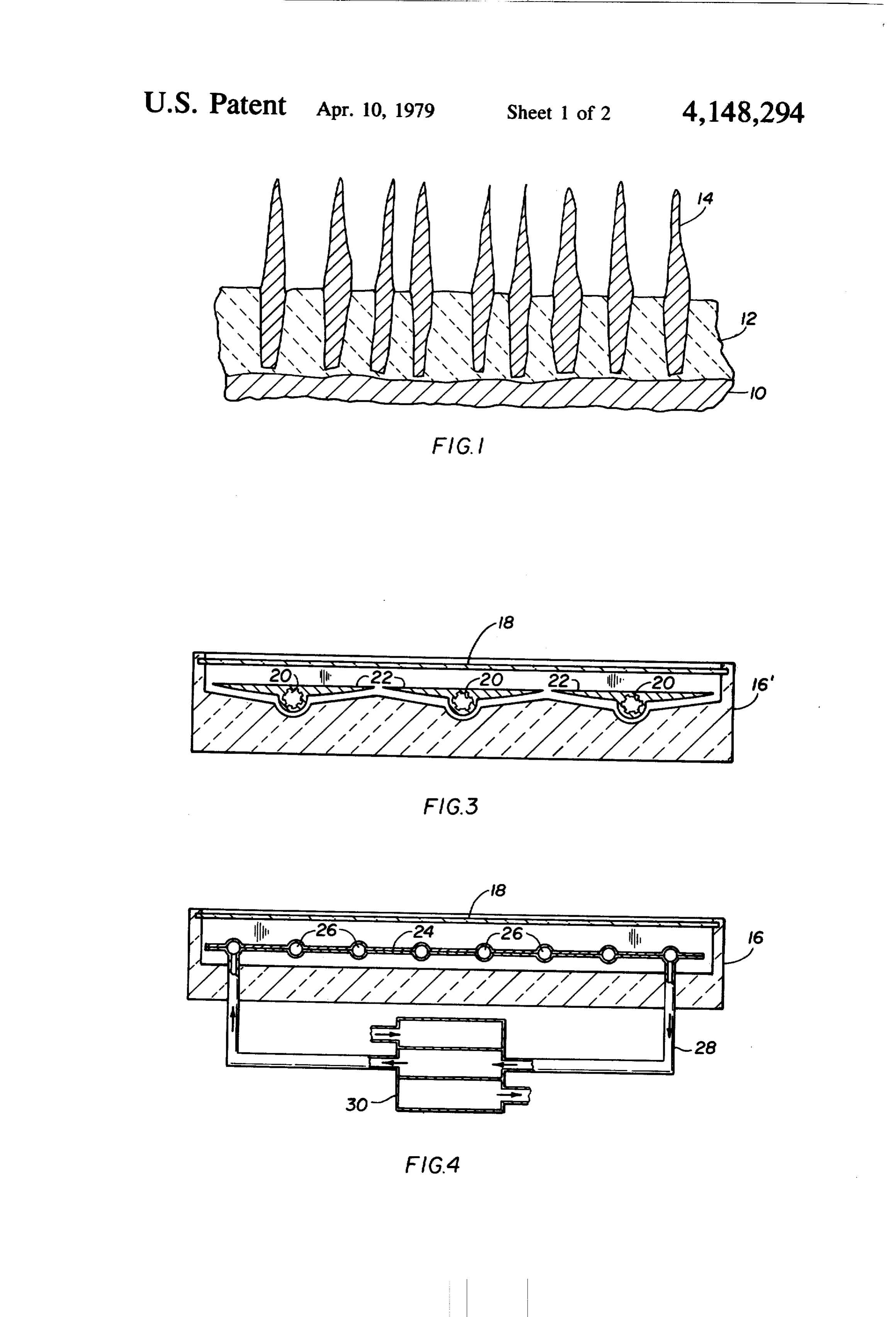
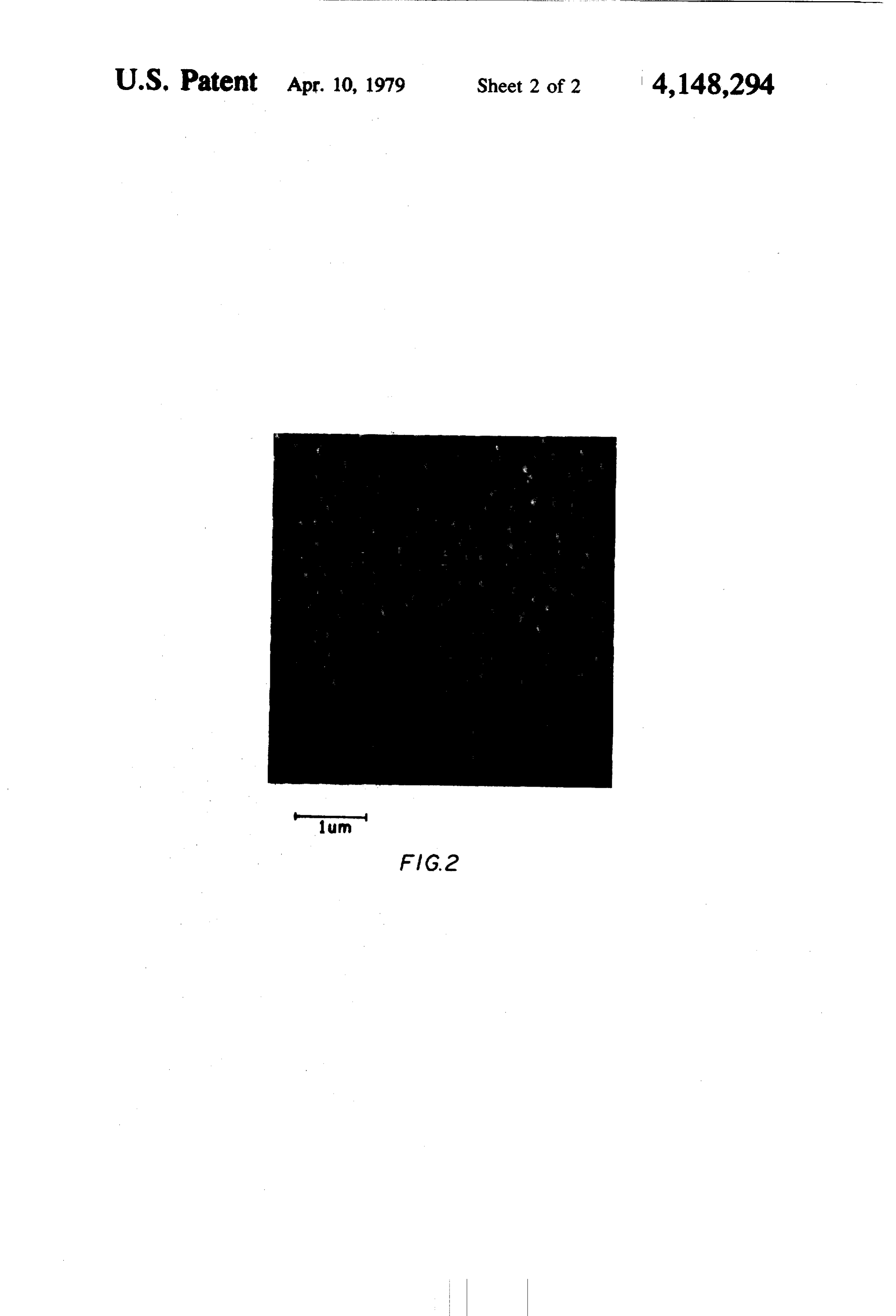
FIG. 2 is an actual photomicrograph of the exposed illustrated.
Page 2drawing sheetscan →
Page 3drawing sheetscan →
Page 4scan →
Referring initially to FIG. 1, there is seen a substrate
SOLAR COLLECTOR PANEL AND METHOD OF 10 of commercially pure aluminum (aluminum 2 S) MAKING which is covered with an integral layer 12 consisting
This invention relates to solar collector panels and to essentially of aluminum oxide. Pores in the oxide layer a method of making the same. 5 receive rods 14 of nickel which project above the oxide The methods presently available for providing solar surface and are transversely spaced from each other. collector panels with surface coatings which impart to FIG. 1 is not drawn to scale, but the thickness of the the panel surfaces high absorptance (a) and low emit oxide layer 12 may not be much greater than 1.0 u and tance (e) were reviewed recently at a symposium of the may be as small as 0.1 u. The pores and the conforming American Elektroplaters' Society (Industrial Finishing, 10 parts of the nickel rods 14 received in the pores have 1976), A coating for aluminum, an otherwise valuable diameters of 0.1 to 0.5 u and are spaced apart 0.1 to 1 u. panel material, which would combine desirable values of a and e with necessary stability at economically areThe freely projecting longitudinal ends of the rods transversely offset from each other, and the alumi acceptable cost was not presented to the symposium.
It has now been found that such a coating can be 15 length of the rods is issuch num oxide surface exposed between the rods. The that the surface defined by the produced at low cost on aluminum and alloys in which aluminum is the predominant component. A solar col ends of the rods and the aluminum oxide surface are lector panel of this invention comprises a continuous spaced, on an average, l to 5 L. The appearance of the coated substrate surface is metallic substrate of aluminum or aluminum alloy. An velvet-like integral anodized layer covers a face of the substrate 20 FIG. 2. Theonspacing a microscopic scale, as is evident from of the individual rods 14 is too and has a thickness not substantially greater than 1 u. small to permit significant emission of radiant heat in the The layer, or at least its surface directed away from the low frequency range of the infrared spectrum. In the substrate, is formed with a multiplicity of pores spaced high-frequency IR range (approximately 1 u), absorp apart 0.1 to 1.0 L and having diameters of 0.1 to 0.5 u.
A multiplicity of elongated metallic bodies are respec 25 tion and emission are equal, but thermal energy is radi tively received in the pores and project from the same ated from the rods mainly at right angles to their sur outward of the anodized surface. faces, and only a small portion of each rod surface is Microscopic nickel rods have been found to be most directed outward of the panel.
effective in producing a surface whose absorptance is Aluminum oxide emits radiant heat readily at 5 to 10 close to that of a black body, but which emits very little u, but such emission is suppressed by making the oxide energy because of its configuration. The free longitudi layer very thin.
nal ends of the nickel rods define a surface formed with Basically conventional solar panel arrangements are recesses which transversely separate the rod ends. The shown in FIGS. 3 and 4. Each of the two arrangements projecting length of the rods and the depth of the reces includes a shallow box 16, 16 of thermally insulating ses should average 1 to 5 L. 35 material whose open top is closed by a glass plate 18. In The afore-described panel is prepared by anodizing the box 16 (FIG. 3), three internally ribbed heat pipes 20 the aluminum or aluminum alloy substrate in an aqueous are attached to the backs of juxtaposed aluminum sheets electrolyte until the porous oxide layer is formed, and 22 which are elongated at right angles to the plane of by thereafter galvanically depositing the metal bodies, FIG. 3 and mounted on the bottom of the box. The such as nickel rods, in the pores by making the substrate faces of the sheets 22 directed toward the glass plate 18 an electrode in an aqueous solution containing appropri are anodized and nickel plated as described with refer ate metal ions, such as nickel ions. ence to FIGS. 1 and 2. As is known in itself, the heat The porous oxide layer is formed quickly at approxi pipes 20 are filled with a fluid heat transfer medium, mately ambient temperature in an electrolyte of dilute such as a low-boiling organic solvent. Solar heat evapo phosphoric acid. The nickel deposit is preferably 45 rates the solvent, and the solvent vapors flow along the formed in a mildly acidic, conventional electrolyte by heat pipes into a heat exchanger in a known manner passing alternating current between the anodized sub evident from FIG. 4. The heat of vaporization of the strate and the solution of nickel ions.
Aluminum and most of its alloys are distinguished by fluidthe is transferred there to water or other liquid, and liquefied solvent is returned to the box. 16 for re good heat conductivity so that a body of heat transmit newed evaporation by solar energy.
ting fluid is readily held in thermal contact with the The box 16" (FIG. 4) encloses a panel 24 which con substrate in a manner conventional in itself. The fluid may be caused to flow between the panel and a heat sists ofother two superimposed sheets of aluminum welded to exchanger through a conduit, as is also known in itself. eachmeandering in area contact and defining therebetween a channel 26. Conduits 28 connect the two
Other features and many of the attendant advantages ends of the channel
26 to a heat exchanger 30. The fluid of this invention will readily be appreciated from the sealed following detailed description of preferred embodi conduits 28, and oneconsisting in the circuit of the channel 26, the part of the heat exchanger 30 is ments when considered in connection with the attached drawing in which: circulated by a thermal siphon effect or in any other FIG. 1 diagrammatically illustrates the surface struc desired manner to transfer solar energy from the panel ture of a solar panel of the invention in cross section on changer 30 inliquid 24 to another which passes through the heat ex a conventional manner not specifically a greatly enlarged scale;
FIG. 2 is an actual photomicrograph of the exposed illustrated.
panel surface obtained by means of a scanning electron The face of the panel 24 directed toward the sun microscope; 65 through the glass plate 18 of the box 16" is anodized and FIG.3 shows a solar panel arrangement of the inven plated as shown in FIGS. 1 and 2.
tion in elevational section; and The following Example illustrates a finishing method FIG. 4 illustrates another solar panel arrangement. which readily produces the desired coating.
Page 5scan →
EXAMPLE aluminum substrate when alternating current passes between the electrolyte and the porous aluminum oxide
Two sheets of aluminum alloy 51 S were pressure surface. The frequency of the alternating current is not welded by the method of U.S. Pat. No. 3,273.227 to important. It is not yet fully understood why nickel form the panel 24. The panel was carefully cleaned by s deposits produced by means of direct current, while brushing, the ends of the channel 26 were slugged, and feasible, do not produce an equally favorable ratio of one of the major faces of the panel was coated with a c/e as the a.c. deposits. Agitation of the plating and stop-off lacquer. The panel so prepared was further anodizing solutions during current flow is not necessary cleaned by immersion in an alkaline, aqueous cleaning and preferably avoided. It is equally unnecessary to bath having a slight etching effect, carefully rinsed free O agitate the panel serving as an electrode. of cleaning solution, wired for current supply, and im mersed in 15% (by weight) solution of phosphoric acid (Fe.While Co), the other transition metals of the iron group copper, tin and zinc can be electrodeposited at 32 C. A potential of approximately 12 to 14 volts was from aqueous solutions of their sulfates on the anodized applied for approximately seven minutes between the aluminum substrate, they are less effective than nickel in panel as the anode and a lead cathode. An initial current ls density of 3 amps./sq. dm dropped ultimately to 0.3 modifying the a/e, ratio, and favorable effects initially amps. /sq.dm during anodizing. The thickness of the observed expected decrease relatively fast. In the absence of significant other advantages, the alternate anodized coating was approximately 1 u. metal deposits were not yet investigated in detail. The anodized panels were carefully rinsed in water It should be understood, of course, that the foregoing until the washings became neutral, and then immersed 20 in a solution at room temperature containing 50 g Ni disclosure relates only to preferred embodiments of the SO4.7H2O, 20g HBO and 2.5 ml glycerol per liter. An and invention, and that it is intended to cover all changes alternating potential of 8 volts was maintained between chosen modifications in the examples of the invention the panels and a nickel counterelectrode for 10 minutes. herein for the purpose of the disclosure which The anodized and nickel plated panels then were rinsed 25 do not constitute departures from the spirit and scope of in several changes of cold water, sealed in water at 90' theWhat appended claims.
is claimed is:
C., and ultimately airdried. The panel surface so pro duced appeared black to the naked eye, and a photomi 1. A panel capable of absorbing incident solar energy crograph is shown in FIG. 2. The pointed ends of the absorbedat a high rate and of radiating only a small portion of the rods appear rounded due to a sputtered gold deposit 30 energy, said panel comprising: conventionally applied prior to photographic exposure. (a) a continuous metallic substrate consisting predom The absorbitance value a for the finished surface was inantly of aluminum;
practically 100%, and the emittance value e was below (b) an anodized layer covering a face of said substrate 10% for the temperature range from 60' to 100' C. and being integrally bonded thereto, which is of greatest practical importance at this time. 35 (1) said layer consisting predominantly of alumi Virtually the same result was achieved with other alu num oxide, minum alloys containing magnesium and manganese as (2) said layer having a surface directed away from the principal alloying ingredients, but other aluminum said substrate and formed with a multiplicity of alloys containing copper, silicon, chromium, and zinc pores spaced apart O. to l l and having a diame were found also to be suitable. ter of 0.1 to 0.5 l; and A phosphoric acid electrolyte permits close control (c) a multiplicity of elongated metallic bodies respec of pore size and pore spacing by varying acid concen tively received in said pores and longitudinally tration, temperature, applied voltgage and anodizing projecting outward of said surface. period, but preliminary tests indicate that sulfuric acid 2. A panel as set forth in claim 1, wherein said bodies may also be employed although it requires more critical 45 essentially consist of nickel.
maintenance of operating variables. So far. we have not 3. A panel as set forth in claim 2, wherein said surface been able to duplicate the a/e, ratio readily available in is exposed between the projecting portions of said bod phosphoric acid by anodizing in sulfuric, oxalic, or eS.
chromic acid electrolytes. 4. A panel as set forth in claim 3, wherein the thick It is usually more convenient to maintain an approxi 50 ness of said layer is approximately 1 p. mately uniform voltage between the electrodes in the 5. A solar collector arrangement comprising a panel anodizing cell during the brief period of electrolytic as set forth in claim 2, and fluid retaining means for action. However, this is not critical, and a more uniform holding a body of heat transmitting fluid in contact with current may be maintained, if so desired, by increasing said substrate.
the voltage as the oxide film forming on the aluminum 55 6. An arrangement as set forth in claim 5, further surface raises the resistance of the cell. comprising a heat exchanger remote from said panel, The mildly acidic nickel plating solution described and a conduit connecting said fluid retaining means to above is known. It has been found to yield the desired said heat exchanger for flow of said fluid therebetween. nickel deposit without attacking the oxide film on the t k
Provenance
- Collection
- Patents citing this work
- Pages
- 5
- Method
- pdftotext (the PDF's own text layer) + pdftoppm 300dpi page scans
- Patent office record
- patents.google.com →
- Source
- Google Patents citing-documents table
- Assignee
- Dornier System Gmbh
- Published
- 1979-04-10
- Transcribed from
- patentimages.storage.googleapis.com →