

patent · US4261329A
Multi-transport modular solar energy system
14 April 1981
Text
Page 1scan →
United States Patent (19)
Walsh et al.
Energy system
Modular solar
76 Inventors: David P. Walsh; Joanne M. Walsh, both of 1400 Ramsey Dr., P.O. Box
51) Int. C.’................................................. F24J 3/02 52 U.S. C. ................................... 126/417; 126/450;
2,167,576 7/1939 Kiser .................................... 26/437 2,920,710 1/1960 Howard ...... ... 180/2. A 3,023,463 3/1962 Bigelow ................................. 52/173 3,095,616 7/1963 Bigelow . ... 52/173 3,348,860. 10/1967 Buckles ....... ... 280/475
3,703,244 11/1972 Walsh ........... a sy. as a a 296/10 3,722,948 3/1973 Walsh ...... ... 296/35.3 4,000,850 1/1977 Diggs ...... ... 126/427 4,119,084 10/1978 Eckels ..... ... 126/430 4,136,668 1/1979 Davis ...... ..., 26/430 4,144,999 3/1979 Zebuhr ... ... 126/427 4,187,831 2/1980 Eubank ....... ... 126/435 4,196,718 4/1980 Neustein .............................. 126/427 Primary Examiner-Herbert F. Ross
An independent, self-contained solar energy module for transportation and fixed accurate positioning, including an expandable transport trailer chassis, adapted to re ceive interchangeable types and sizes of solar energy modules having integral support frames which also engage with the transport trailer chassis. The trailer chassis provides for an adjustable load bearing tandem axle wheel unit and ramping capabilities for effectively loading and unloading the solar energy module units in their fixed accurate position.
7 Claims, 22 Drawing Figures
Drawings
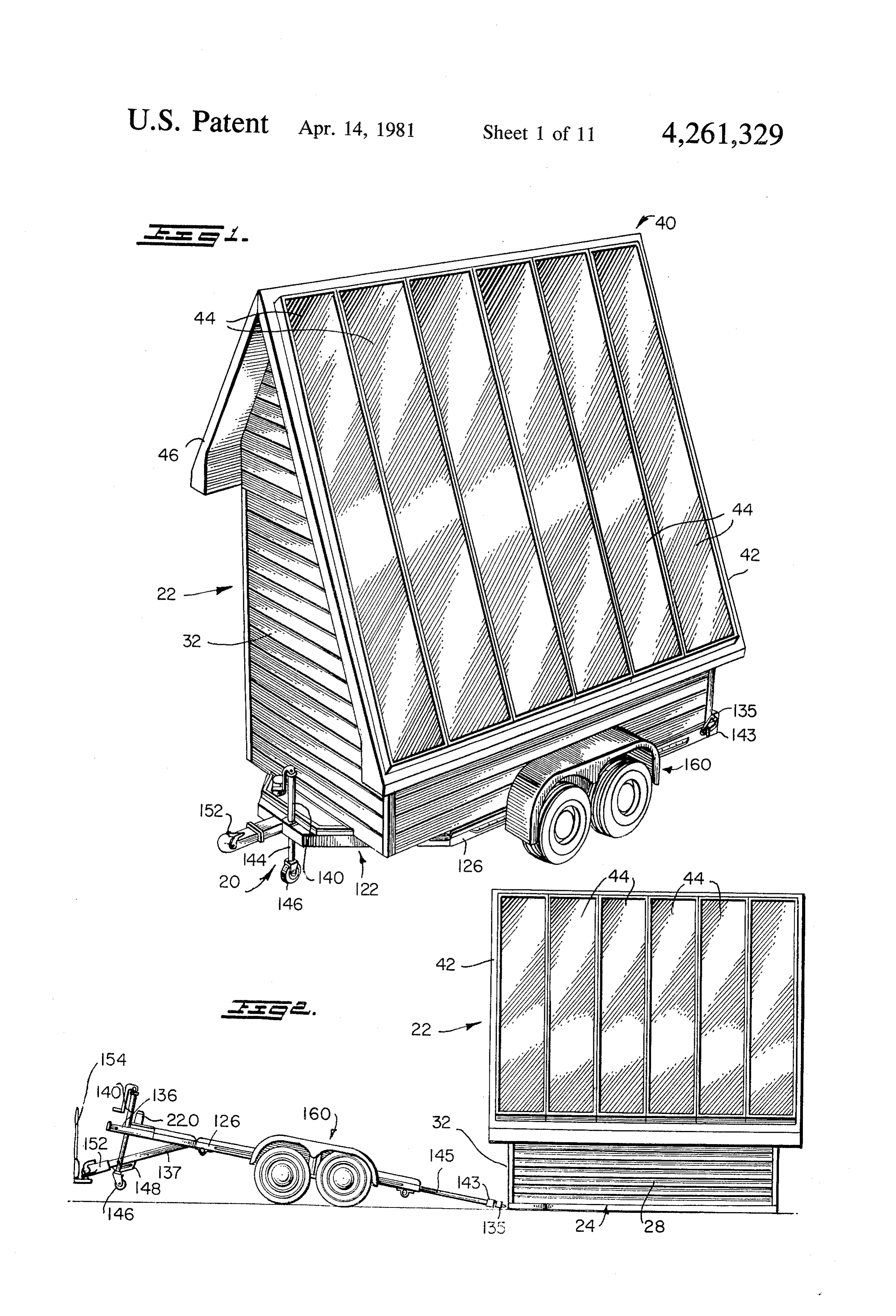
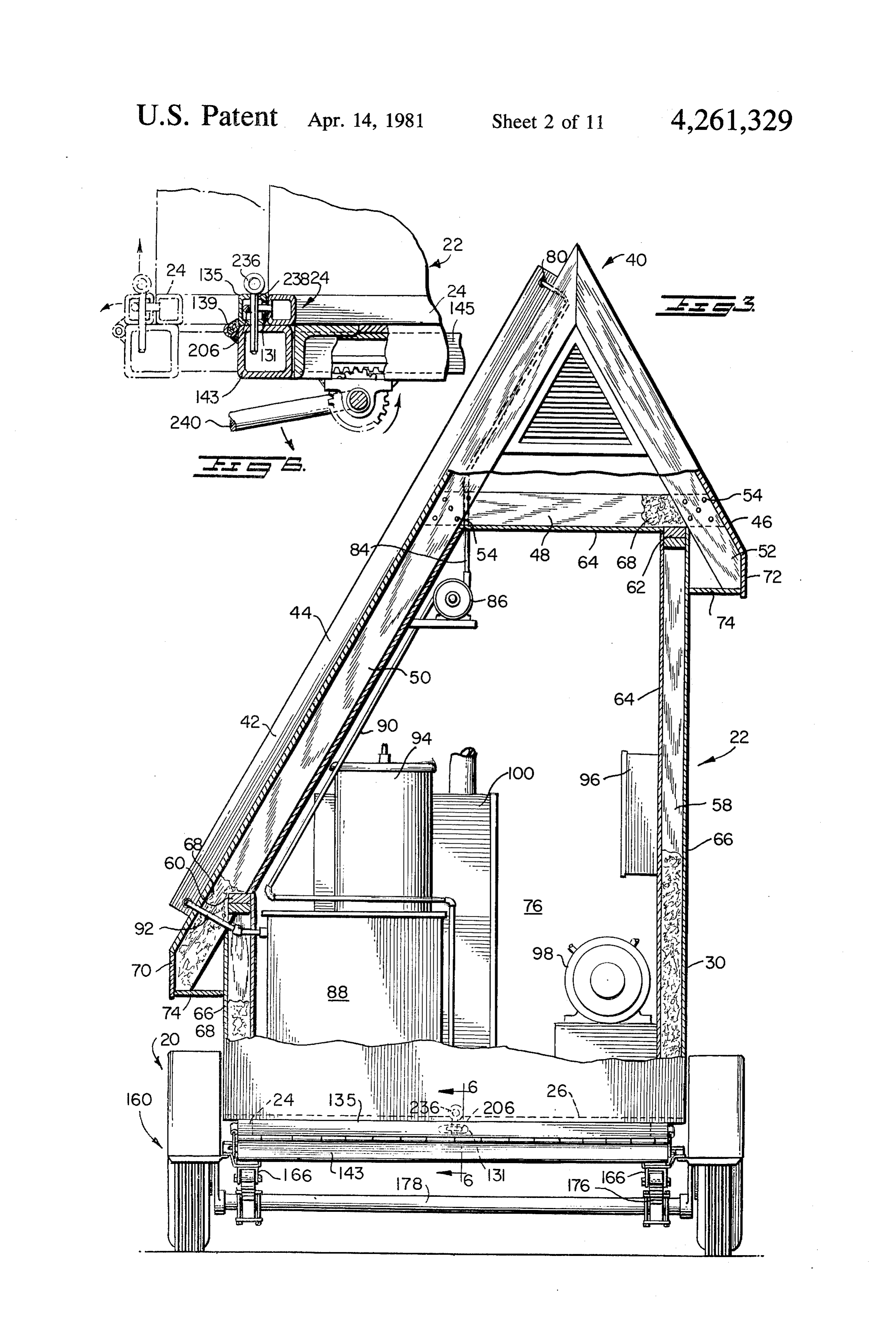
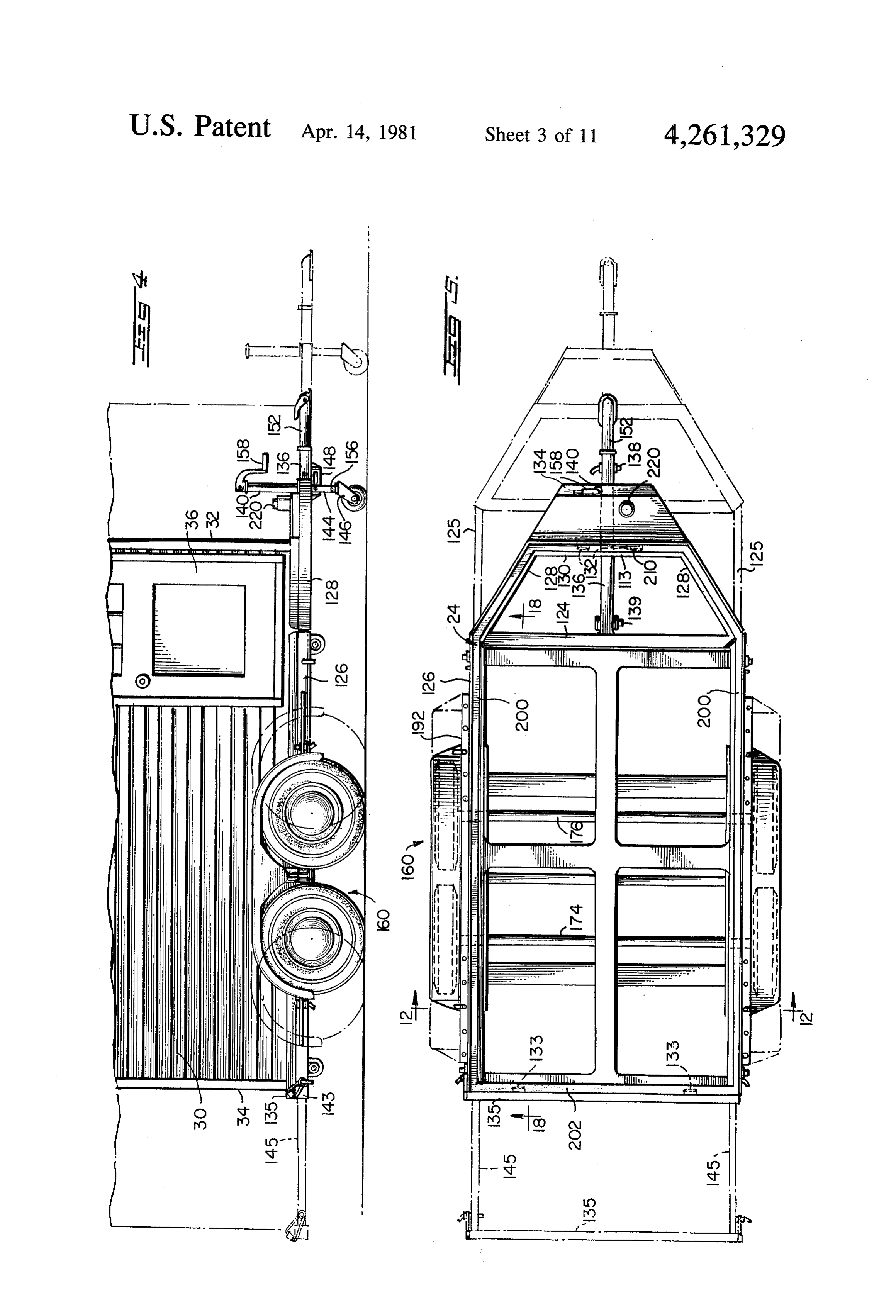
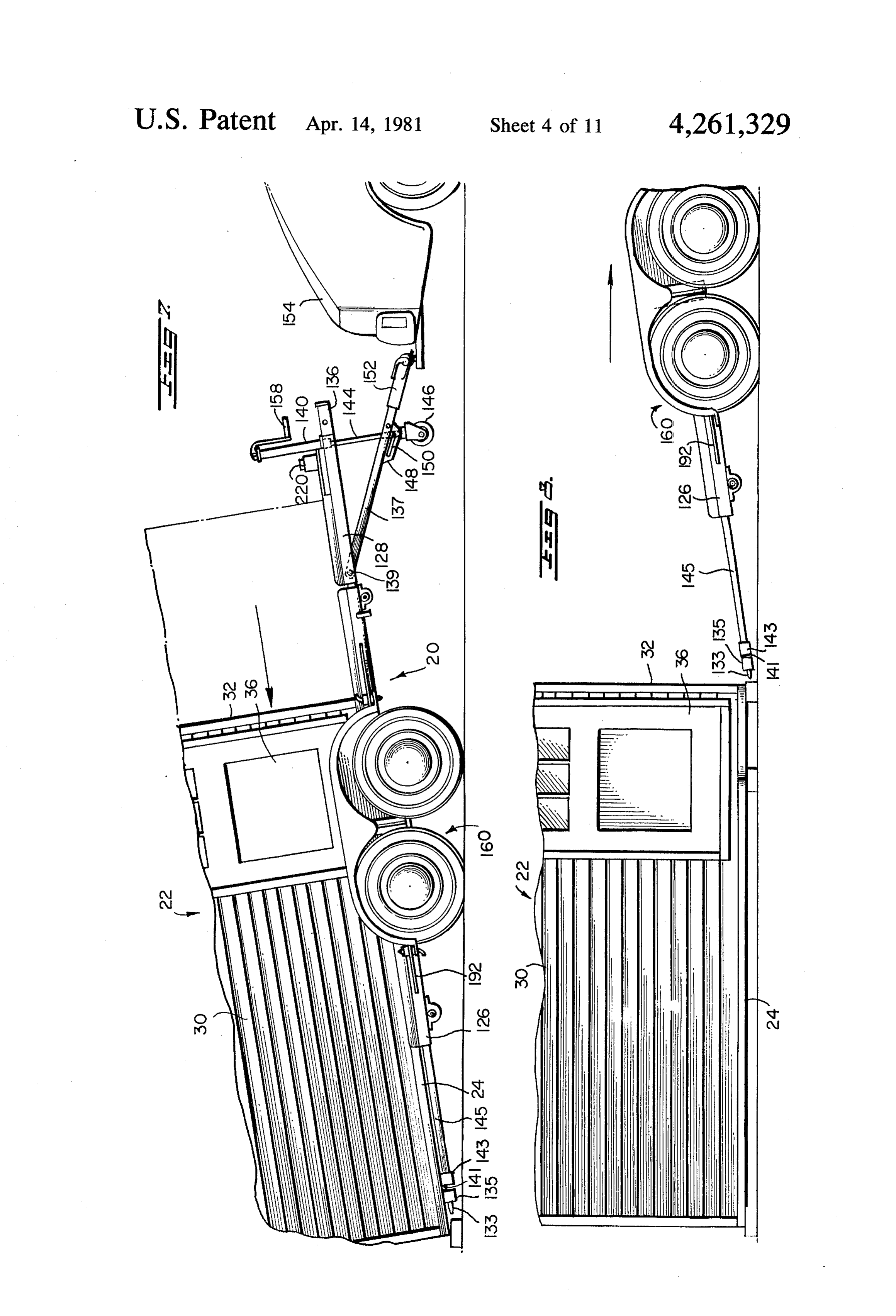
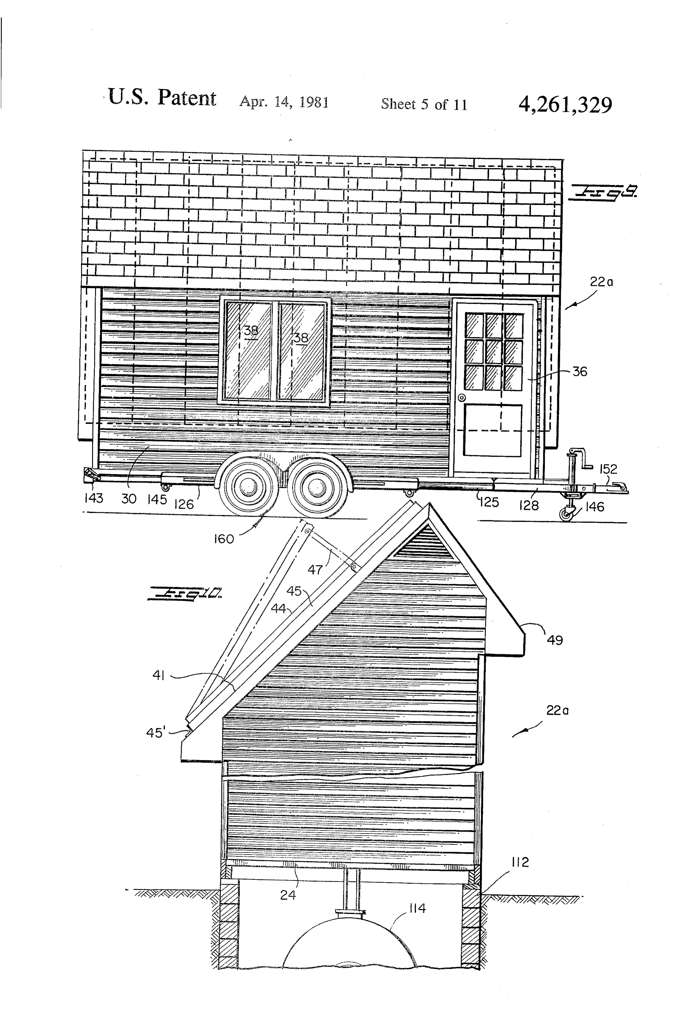
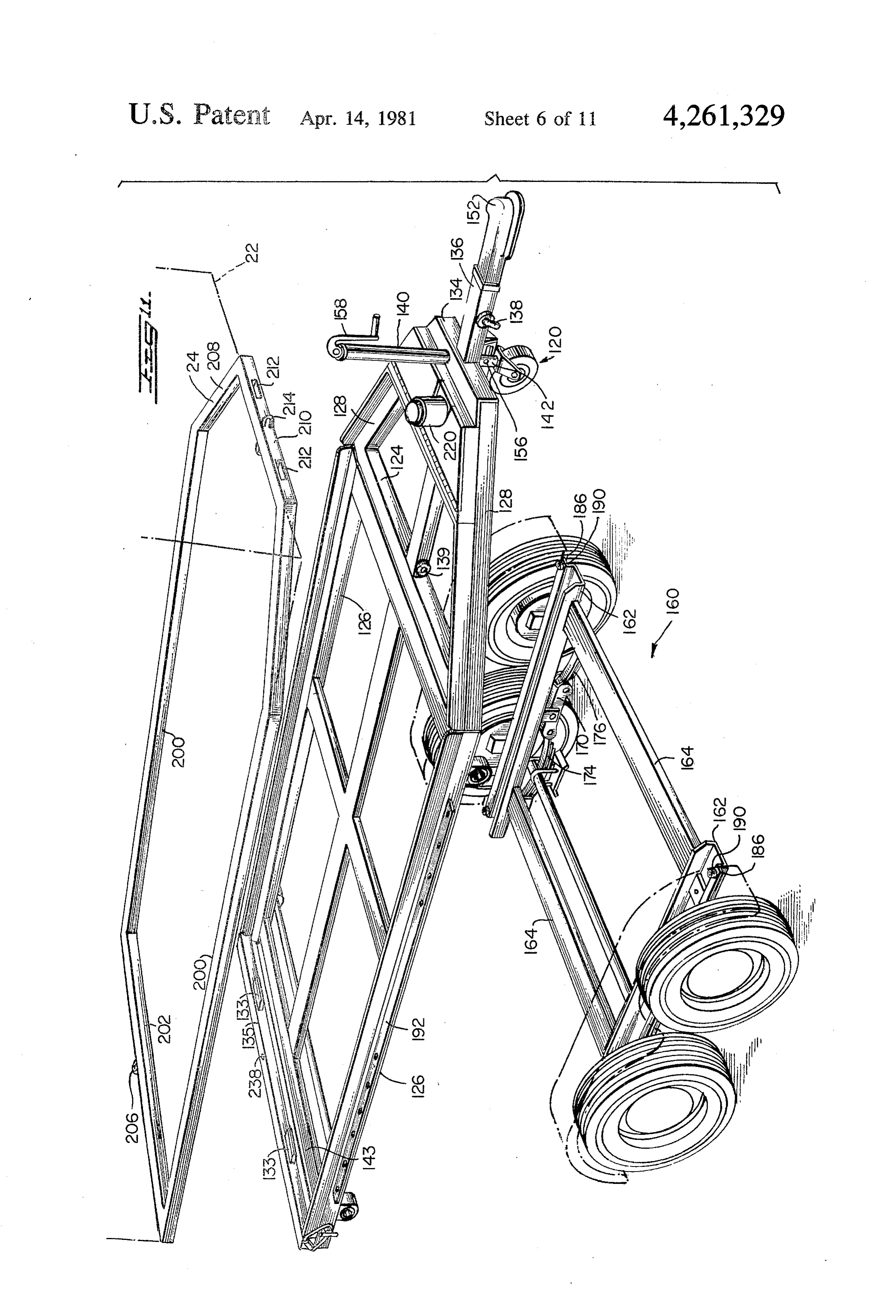
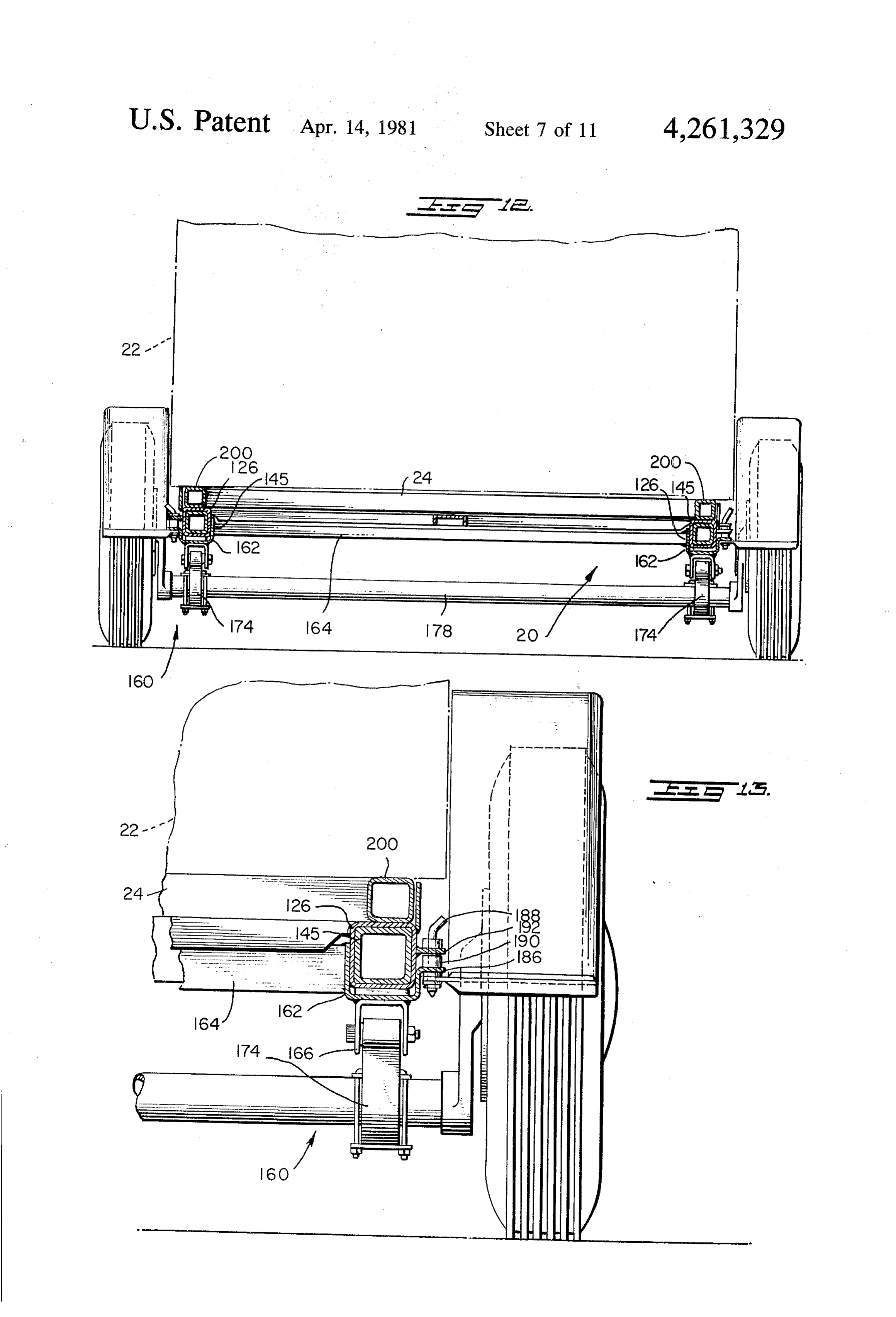
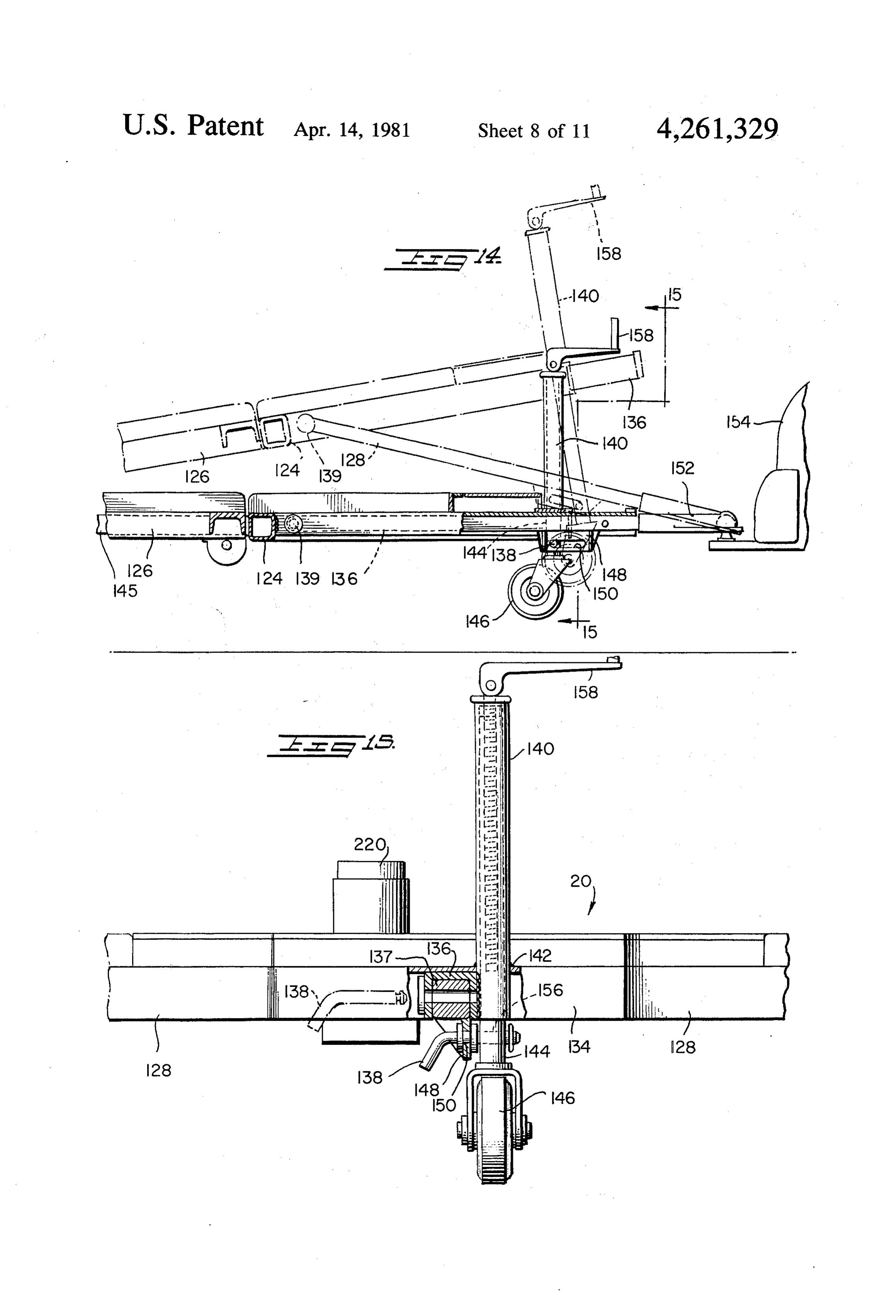
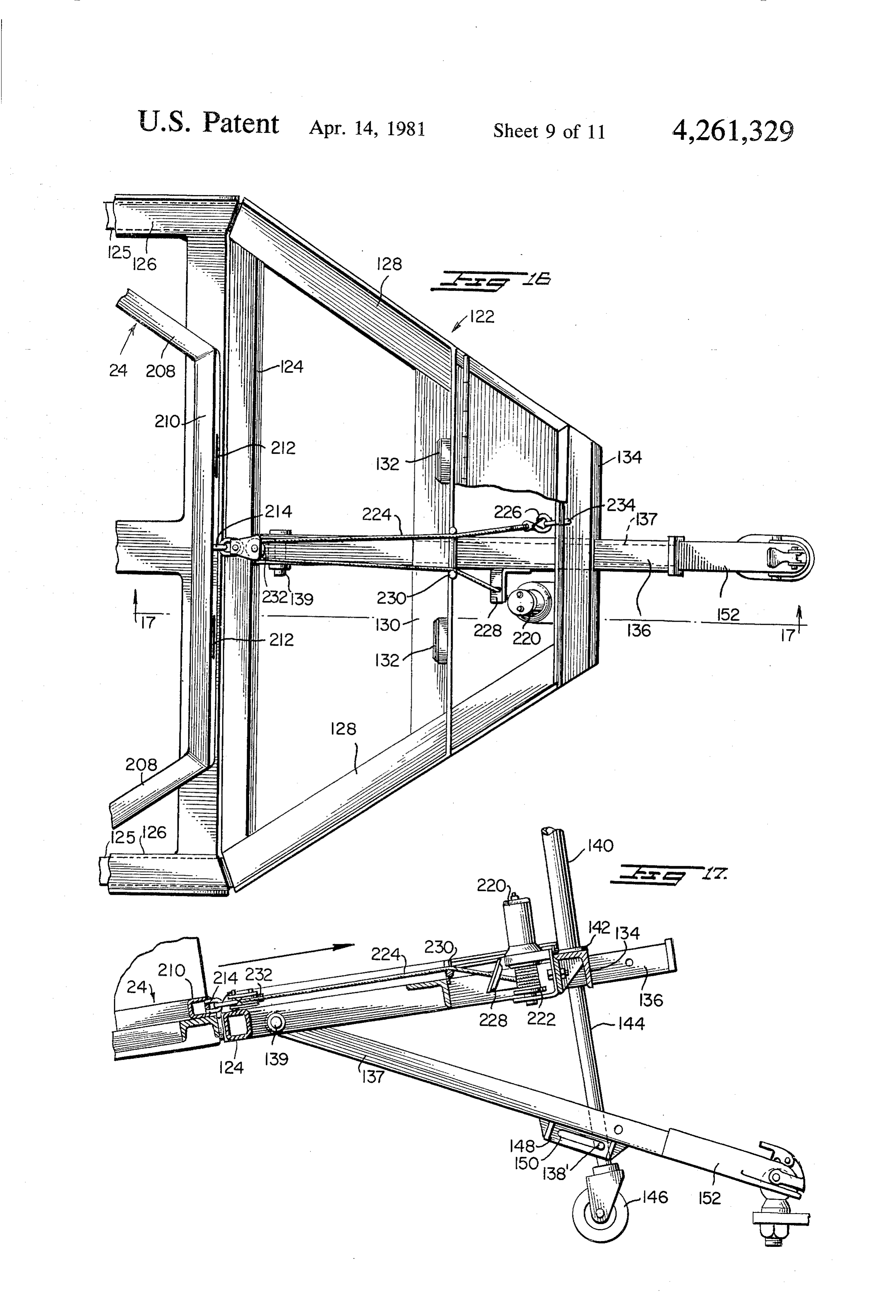
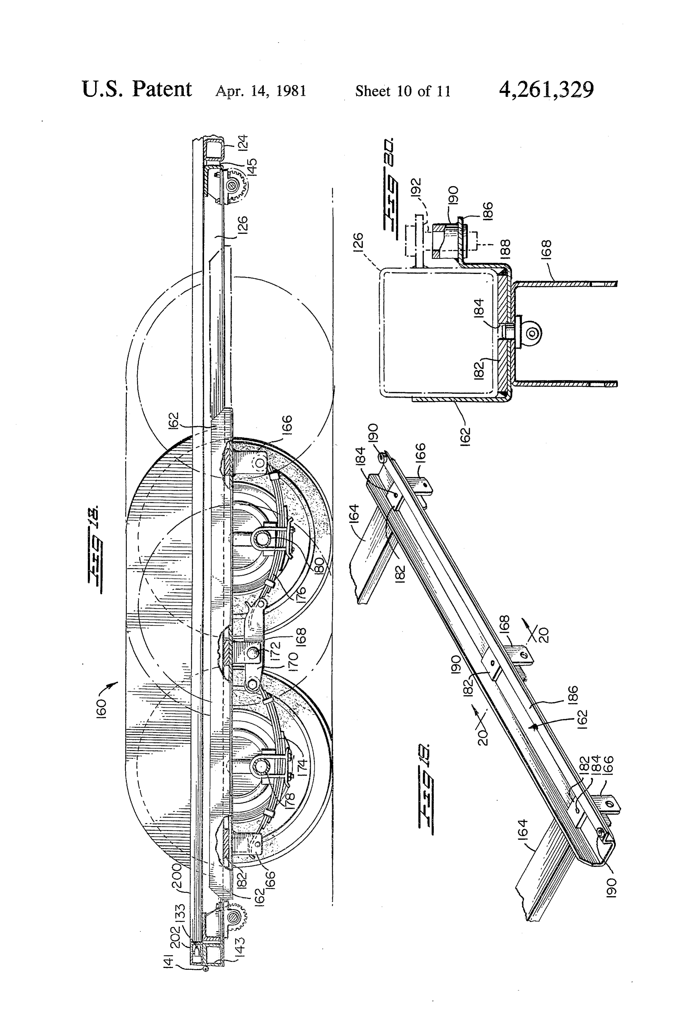
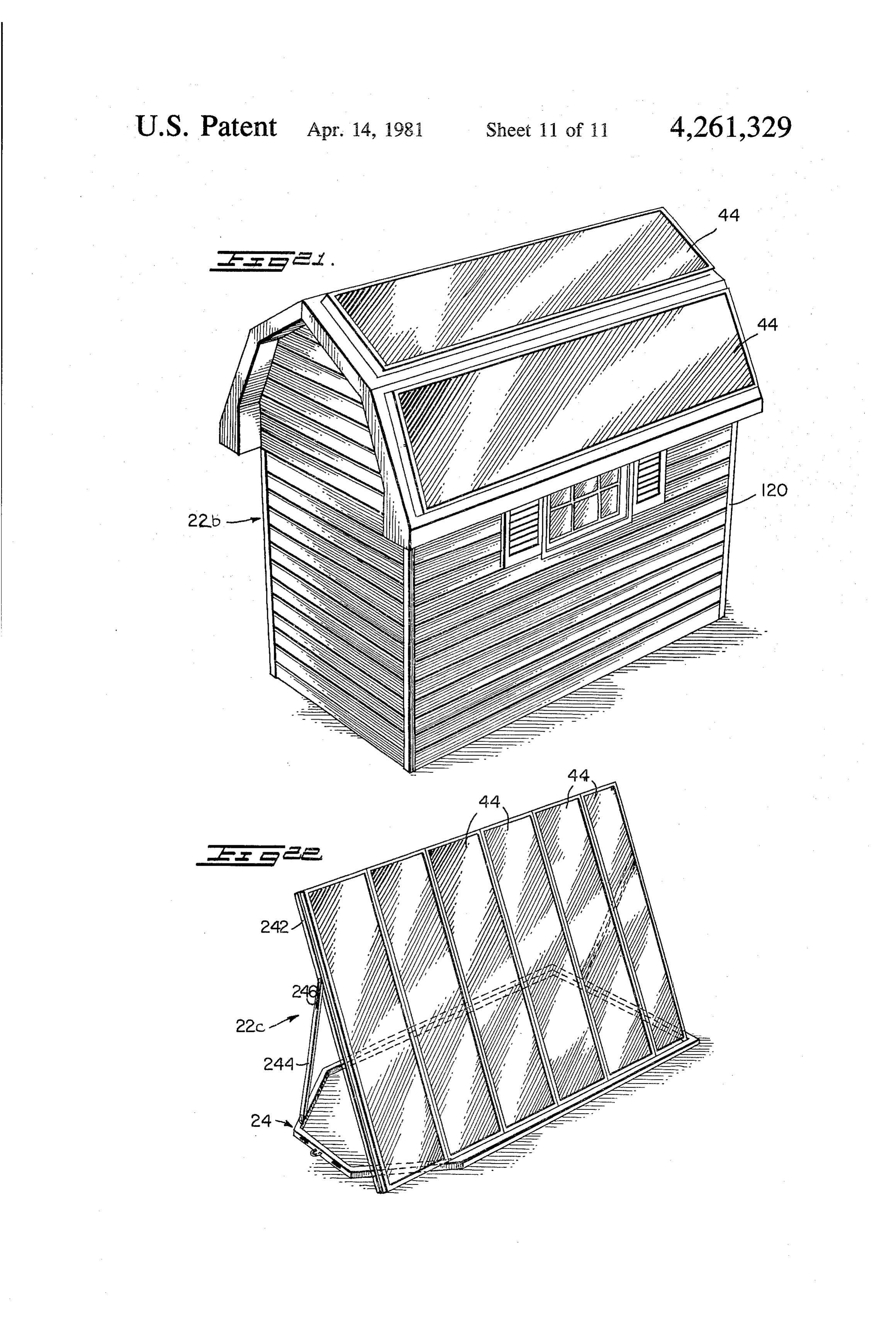
FIG. 3 is a rear elevational view of FIG. 1, partially
Page 2drawing sheetscan →
Page 3drawing sheetscan →
Page 4drawing sheetscan →
Page 5drawing sheetscan →
Page 6drawing sheetscan →
Page 7drawing sheetscan →
Page 8drawing sheetscan →
Page 9drawing sheetscan →
Page 10drawing sheetscan →
Page 11drawing sheetscan →
Page 12drawing sheetscan →
Page 13scan →
MULTI-TRANSPORT MODULAR SOLAR selection of the most desirous system, its most effective
Energy system
location and orientation for solar exposure.
The specific modular structure design consists of an extending angular facing roof dormer, for a southerly
BACKGROUND OF THE INVENTION 5 exposure and having maximum square footage surface It is well known that the application of solar collect area for solar panel mounting. The side wall closures of ing energy and distributing systems of different types the module unit provide a room having sufficient square are in use, and consist of solar collecting panels and footage for housing all of the necessary equipment and associates apparatus as being integrated with an existing energy storage in close proximity to one another, building or dwelling or integrated in the planning and 10 thereby permitting maximum efficiency and mainte erecting of new buildings or dwellings. In the applica nance, along with cost reduction. This modular method, tion of solar collecting and energy distribution to an permits elective types of systems to be installed, such as existing building or dwelling, many problems exist, such hot water heating, space heating, space cooling or com as initially providing for southern exposure and proper 15 binations thereof.
angular inclination of the solar collecting panels. While This system also provides for factory "packaging” at in some instances, an existing southerly facing roof lower cost, along with pre-testing for rating results, dormer may provide a mounting surface for the collect elimination of changes and oversights in design and ing panels, rarely does such a dormer provide the de specification cycling. The integration of the collectors sired angular disposition for maximum efficient perfor and control unit modules, housed within a parent mod mance of the panels. In most instances, a grid system has 20 ule, will shorten installation time dramatically. to be provided for proper panel mounting, resulting in The solar energy modular unit is provided with a increased expense and asthetic unsightliness. The neces structural foundation support frame, when it is "in sary apparatus required in conjunction with the collec place' and interconnected to the structure or dwelling, tor panels, poses another problem, both from the neces 25 to form an operative solar system. The solar module unit support frame also co-acts with a trailer chassis for sary space requirement and remote location from the transportation collection source (such as, storage tanks, pumps, piping cent the structure from a factory, to the elected site adja or ducting, controls etc.) resulting in installation diffi tioning, or dwelling for solar energy condi culties and operational inefficiency due to the impracti thereby permitting orientation of the unit on cal scattered location of the necessary apparatus com the site, so as to direct the solar collectors in a southerly ponents and excessive piping or ducting. While such 30 direction
The for maximum performance.
trailer chassis provides improvements over exist installations will provide a given degree of results, none can achieve maximum performance due to random lo ing U.S. Pat. Nos. 3,703,244 and 3,722,948, in that while attached to a stationary vehicle, the chassis is provided cations, which again result in further costly installa with tilting or ramping capabilities to facilitate easy tions, reduced efficiency and unsightliness. These ran 35 unloading dom types of installations further lend difficulties to the disclosed inofourthe solar unit or any other modular unit as previous patents, from the trailer chas proper maintenance of the systems, since the individual apparatus components co-act with one another to pro sis or conversely, the unit is loaded onto the trailer chassis while in the ramped position, into integral en duce effective results.
gagement with the solar unit foundation support frame
Still another problem existing, is the tie-in with exist to the trailer chassis for transportation. Again, in this ing fuel fired furnaces, hot water heaters, space air heat instance, that while ing, and air conditioning equipment as back up units, to the factory "packaging' previously supply the requirements on low solar days, or when a described offers many benefits, the "package' handling and transportation, provides proven, practical simplic succession of such days result in the ineffectiveness of ity along with modular co-functional structural design stored solar energy. The costly and random installation 45 permitting minimal and safe handling and transporta of a solar energy system becomes a permanent part of an tion.
existing building or dwelling and in cases of property Other and additional advantages and features of the resale, may not meet the desires or needs of a perspec tive purchaser, since, while being suitable for one occu invention lowing become more readily apparent from the fol detailed description of preferred embodiments pant, does not meet the requirements of another in a 50 thereof, when taken practical manner. It is readily understandable that this drawings in which: together with the accompanying entails a very substantial capital investment, also, com FIG. 1 is a perspective view of a solar energy unit in pounding maintenance costs, while greatly decreasing integral the percentage of efficiency and a consequent reduction tation toengagement with a trailer chassis for transpor an installation site.
of return on operation and return on initial investment. 55 FIG. 2 is a side elevational view of a solar energy unit SUMMARY OF THE INVENTION discharged from the trailer chassis.
FIG. 3 is a rear elevational view of FIG. 1, partially
The present invention overcomes the drawback of broken away, showing the solar energy unit in locked known solar installations and for the first time, provides and secured for a transportable, totally self-contained solar energy 60 FIG. 4 is arelationship with the trailer chassis. housing module of varying sizes, designed to provide a opposite side shown in FIG.side fragmentary elevational view of the completely independant energy producing media unit, mounted for transportation on thethetrailer1 of solar energy unit, chassis and separate from, and independant of the existing and out showing the expandable capabilities of the trailer dated equipment. This module permits close proximity sis in phantom line, to accommodate solar energy chas units of all necessary functional solar apparatus housed 65 of varying sizes.
within one modular transportable solar energy unit resulting in maximum efficiency and providing for ease theFIG. solar 5 is a top plan view of the trailer chassis with energy unit support frame in integral locked of installation for desired results. This then permits and secured relationship therewith, (body unit not 14 shown) and the expandable characteristics in phantom elongated slanting dormer 42 for accomodating maxi-. ine of the trailer shown in FIG. 4. mum length solar collecting panels 44. The previously FIG. 6 is an enlarged fragmentary sectional view described offset ridge 40 provides a conventional oppo taken along the line 6-6 of FIG. 3, showing the means site dormer 46 terminating an appropriate distance from by which the solar energy unit is disengaged from 5 the ground to permit installation of doors 36 or win locked and secured engagement with the trailer chassis. dows 38 in a conventional manner. The "A" shaped FIG. 7 is a side elevational view similar to FIG. 4, dormered ridge roof structure is provided with trans showing the solar energy unit partially removed from verse joist members 48 secured to dormer trusses 50 and the ramped trailer chassis. 52 as seen at 54. The side walls 28 and 30 comprise FIG. 8 is a fragmentary side elevational view, further 10 vertical stud members 56 and 58 which have support showing the solar energy unit completely discharged caps 60 and 62 for engagement and support of the super from the trailer chassis. structure comprising the dormer trusses 50 and trans FIG. 9 is a side elevational view of a larger solar verse joist members 48. The interior walls constitute energy unit in locked and secured engagement with the fireproof sheetrock or the like as indicated at 64 and trailer chassis in an expanded condition. 15 exterior sheathing 66 with appropriate effective insula FIG. 10 is a rear elevational view of the modified tion 68 applied therebetween. The sheathing of the solar unit in FIG. 9, as being removed from the trailer outer walls 28, 30, 32 and 34 may be covered with the and secured in place over a storage pit, shown in cross conventional black felt and siding comensurate with the section. choice or accompanying decor that is compatible with FIG. 11 is an exploded perspective view of the trailer 20 the existing structure that the solar unit is to serve. The chassis components and the solar energy unit support same is applicable to the roofing materials. The angular frame. sloping dormers 42 and 46 extend downwardly and FIG. 12 is a transverse sectional view taken along the outwardly from the ridge and beyond the vertical side line 12-12 of FIG. 5, showing the cooperative arrange walls 28 and 30 to form overhangs having facia plates 70 ment of the trailer and solar energy unit body support 25 and 72 with soffit returns 74. The width extremities of frame in integral engagement. the transportable solar modular unit 22 is defined by the FIG. 13 is an enlarged detailed fragmentary sectional facia plates 70 and 72, so as to constitute a federal and view of the right hand side of FIG. 12. state legal limit for transportation purposes without FIG. 14 is an enlarged detailed elevational view par necessitating a "wide load” permit. The enclosure room tially broken away, of the forward part of the trailer, 30 solar equipment placement area indicated by the refer showing the means for ramping the trailer chassis. ence numeral 76, will hereinafter be described. FIG. 15 is an enlarged detailed fragmentary sectional As seen from the foregoing, the solar energy module view taken along the line 15-15 of FIG. 14. 22 constitutes a structurally sound facility of a configu FIG. 16 is an enlarged detailed top plan view of the ration so as to provide an asthetically acceptable struc forward portion of the trailer showing the means for 35 ture designed for functional capabilities for effectively winching the solar energy unit support frame, shown providing maximum solar collecting surface and pro partially conveyed, for locking engagement with the tected equipment installation area.
trailer chassis. Since the equipment required for the various types of FIG. 17 is a detailed fragmentary longitudinal sec installation, i.e., hot water heating, hot water space tional view taken along the line 17-17 of FIG. 16. heating, hot air space heating or combination thereof FIG. 18 is an enlarged detailed fragmentary sectional are variable, the solar room equipment placement area view taken along the line 18-18 of FIG. 5, showing the 76 provides suitable floor space and area for the differ adjustable tandem axle wheel assembly. ent components required, dependant upon the specific FIG. 19 is a perspective view of one of the cradle system to be employed.
units for the adjustable wheeled unit assembly. 45 The solar collector panels 44 may be of the flat plate FIG. 20 is an enlarged detailed sectional view taken type having an inlet port 80 and an outlet port 82. The along the line 20-20 of FIG. 19. solar collector panels 44 may also be of the concentra FIG. 21 is a perspective view of a modified form of a tor type having parabolic or hyperbolic reflective con solar energy unit. centrator surfaces. It may be pointed out, at this time, FIG. 22 is a perspective view of a still further modi 50 that different types of collectors and systems are more fied form, showing a solar collection unit. advantageous under given conditions, whether they be Referring now in more detail to the drawings, a location or climatic. There is no attempt made in this trailer chassis generally indicated at 20 is shown, which application to point out particular integrated compo is adapted to receive a modular solar unit 22 generally nents, such as, collectors, storage, exchangers, boilers, indicated, for transportation to a predetermined site for 55 heatpumps, controls or the like, due to the variances discharge from the trailer 20 onto a site location, as best mentioned above. For the sake of disclosure and opera seen in FIGS. 1 and 2. The trailer 20 and its solar modu bility of the modular solar energy unit of this applica lar unit handling capabilities will be hereinafter de tion, however, indications are made regarding appropri scribed. ate equipment which may be installed in close working Referring now more particularly to the solar energy 60 relationship at the solar collection source and within the module 22 (FIGS. 1-11) is provided with a foundation protected environment of the equipment room 76. support frame structure 24 having flooring 26 secured Referring again, and more particularly, to FIG. 3, the thereto, and vertical upright side walls 28 and 30 and inlet port 80 of the solar collector panel 44 is connected end walls 32 and 34 securely fixed thereto. As best seen to an inlet fluid feed line 84 to a circulating pump 86 and in FIG. 3, the side walls 28 and 30 are of unequal height 65 then to a fluid storage tank 88 by way of feed line 90. to facilitate and effect the support of an offset ridge The outlet 82 of the solar collector 44 is connected to dormered roof generally indicated at 40, and is hereinaf the fluid storage tank 88 by way of outlet line 92. This ter described. The offset ridge roof 40 provides for an type of installation may be of the closed loop variety 15 and may heat the stored fluid by means of an exchanger, able types of trailer bodies.6The individual interchange not shown, within the tank 88. The fluid employed able type trailer bodies are each provided with substan within the collector loop may be of a different type than tially identical foundation support frames and each of that within the storage unit 88 and consequently, oper these support frames is so constructed and interrelated ate by means of a heat exchange method or may form a with the construction of the main chassis frame, so as to continuous recirculation of the stored fluid, until such time that appropriate temperatures are achieved or in be selectively interchangeable, whereby each body type can be utilized with a common modular chassis frame.
the absence of solar rays. A hot water storage tank 94 In accomplishing this result, the main chassis frame 20 is may be employed in conjunction and in series with the extensible, both forwardly and rearwardly, and has a system, or singularly, where hot water storage only is 10. feature, a bed or recess of generally 'A' shape at its required. A program panel 96 is shown, and may be forward portion, employed to regulate in timed sequence, the various support frame to which permits the body foundation components that are used with a particular installation. therein. The foundation supportwholly be mounted and contained
A heat pump 98 is shown which may operate as a mating generally 'A' shape at its forward24end frame includes a portion booster unit to a given installation or may operate and 15 and the configuration serves to provide support function singularly by itself when required. An air con load bearing manner substantially the entire length inanda ditioning unit 100 is shown within the area 76 for em ployment of a particular system and operated by means structure The of a body mounted thereto.
heretofore mentioned ramping effect of the of the control panel 96. The control panel 96 may oper trailer chassis is accomplished by employment of the ate independantly through programming or by means of 20 retracted nose wheel support generally indicated at 120, thermostats within the structure or dwelling. and constitutes one of the improvements over this pa In the instance where a greater number of collector tent. The support nose wheel 120 is located at the for panels are required, a larger solar energy unit 22a, such ward portion of the truncated "A' frame portion gener as that shown in FIG. 9 on the expanded trailer chassis, ally indicated at 122 and having a rear transverse end may be mounted over a pit 112 (FIG. 10) of conven 25 124 adapted for mating engagement with the forward tional structure such as concrete block, having proper ends of the longitudinal trailer chassis frame members insulation and the larger solar energy unit 22a may be 126, and integral with box girders 125, being telescopi anchored thereto in a conventional manner as shown.
The pit 112 contains a large storage 114 and coopera iscally mounted within the members 126. The 'A' frame composed of merging channel members 128, which tively functions in a conventional manner with the solar 30 form an engageing and supporting seat for the leading energy unit. The elongated dormer 41 is shown at a end of a nested and mated foundation support frame 24, greater angle than that shown in FIG. 5 and the solar collector panels 44 are mounted within a unitary grid when mounted on the trailer chassis frame 20. The inner front member of the truncated 'A' frame comprises a support system 45, pivotally mounted as at 45' and an transverse beam 130, having spaced retainer lugs 132 gularly operative by control arm 47 terminating within 35 extending therefrom, of a similar nature to the lugs 133 the solar unit 22a . Means for operating the angular disposition of the control panels 44 may be provided by at the rear, fixedly secured to a transverse member 135 conventional automatic controls, not shown, from pivotally (which supported at 141 to a transverse box beam 143 provides a supporting seat for the rear trans within the solar unit, or by manual operation.
Referring now more particularly to the trailer chassis fixedly secured to the verse member of foundation support frame 24) 20, which is adapted to receive, in engaged nesting and girders 145 being telescopicallybox longitudinal girders 145, said mating relationship, the foundation support frame struc longitudinal trailer chassis frame members within mounted the the ture 24 of the solar energy unit 22 for transporting. The trailer chassis 20, due to its construction, described in trailer chassis frame. The transverse beam member 130, detail hereinafter, is adapted to receive and mount in a 45 verse memberaofsupporting also provides seat for the forward trans secure manner different modular unit types or styles. particulars herein described aresupport the foundation more frame 24. The clearly seen in
Additionally, and of significance in the present inven FIGS. 11-17 and the various components are more fully tion, is the capability of the trailer chassis to be extended described hereinafter. The forward portion of the trun in length, so as to mount, nest and support modular units, not only of different types and configurations, but 50 cated “A” frame structure is provided with a transverse trunction member 134 integral with the converging also of different longitudinal lengths or sizes. Addition channel member ally, the trailer chassis is capable of being inclined while verted “U” shapedends 128. A forwardly extending in channel member 136 is welded or in the stationary towing condition so as to provide a fixedly secured to the previously ramp for facilitating loading and unloading modular member 124 and extends forwardlydescribed transverse units. This capability will be hereinafter described. 55 chassis frame, a substantial distance beyond the of and medially the trans
A further improvement of the trailer chassis is the verse truncation member 134. Approximate the trans ability to longitudinally adjust the tandem axle running verse member 124 and pivotally mounted as at 139 gear and will also hereinafter be described.
For particular structure and understanding without within the inverted “U” shape member 136, an elon the above described improvements of the trailer chassis nested andhitch gated ball extension lever arm 137 is retained in secured position for towing, by means of a frame construction, specific reference is made to our locking prior U.S. Pat. No. 3,722,948, wherein specific detailed mountedpintelescopic 138. The modified conventional vertically support nose wheel 120, is fixedly description of the various components and functions are secured at one end of the outer telescopic tube 140 to made in detail and the necessary understanding of these details may be had by reference to this patent. Briefly, 65 theReferring transverse truncation member 134, as at 142.
now more particularly to FIGS. 14-17, the the trailer provides a multi-use transport system, inner telescopic tube member 144 is provided with a wherein a main chassis for a trailer, can be had for pivotal nose wheel support 146 at its lower end. The multiple usage by association therewith of interchange tube 144 is in the telescoped retracted condition while 16 being towed (FIGS. 14 and 15). A bracket 148 is fixedly - From the foregoing, it is understood that the tandem ecured to the underside of the pivotal ball hitch exten axle wheel suspension system 160 is mounted to inter son are 137 and is provided with an elongated slot 150 connected “U” shaped channel members 162 for nested therein. A conventional heavy duty ball hitch 152 is engagement with and longitudinal movement as a single secured to the outer end of the pivotal extension lever. 5 truck unitywith the longitudinal chassis frame members 137 and is adapted for engagement with a conventional. 126. Positioning of the truck 160 on the chassis is ac ball mounted to the rear of a towing vehicle 154. . . . . complished by locking pins 188 through apertures From the foregoing, it will be understood that when within the flange, rails 192 and spacer elements 190 of the trailer chassis unit is in position and connected to the: the truck unit 160, thus insuring positive positioning and stationary towing vehicle 154 to discharge or receive a 10. effective load bearing distribution to the expandable solar energy unit mounted on a foundation support. trailer chassis 20.
frame 24, a tilting or ramping effect of the trailer chassis The body foundation support frame 24 can be made 20 is accomplished by removal of the pin 138 from its with lengths commensurate with the dimensions of a towing position and inserted in the slot 150 of the body to be secured thereon, but for different lengths, bracket 148 and extends through an opening 156 of the 15 have a substantially identical structure. This structure lower portion of the telescopic tube 144 adjacent the includes longitudinal side rails 200, preferably of box nose wheel 146, at which time, a crank 158, rotatably shape, interconnected at their rear ends by transverse mounted at the upper end of the outer telescopic tube ings members 202 which is provided with elongated open 140, when rotated provides extension of the telescopic 204, therein, formating engagement with retainer members 140 and 144, which effectively causes the 20 lugs 133, when in nested relation with the foundation forward truncated “A” portion of the trailer chassis 20 support frame 24 and trailer chassis bed 20. A hook-eye to rise and separate by means of a pivotal action at 139, member 206 is attached to transverse rear member 202 thereby accomplishing a tilting effect which lowers the and serves to facilitate removal of the foundation sup rear section of the trailer chassis 20 best seen in FIGS. port frame 24 and its accompanying body unit from the 14 and 17. This tilting action provides a ramped surface 25 trailer chassis. The forward end of the foundation sup in close ground or foundation approximation for easy port frame 24 is truncated 'A' frame configured as at and safe discharge of the modular unit onto ground or 208 to the interior of the 'A' frame channel members foundation engagement. . 128 and of substantial equal dimensions therewith. The A further improvement of the present trailer chassis forward end of the 'A' frame consists of a transverse provides for longitudinal positioning of the tandem 30 member 210 having openings. 212 therein for mating axled wheel unit generally indicated at 160. This unit engagement with retainer lugs 132. A hook-eye member 160 constitutes a unitary truck having substantially “U” 214 is also attached to transverse member 210 and shaped channel members 162 which surround the longi serves to facilitate mounting and nesting of foundation tudinal trailer chassis frame members 126 in cup-like support frame 24 in the bed provided by the trailer fashion for longitudinal reciprocal positioning thereon. 35 chassis 20.
The channel members 162 are securely fixed in trans From the foregoing description of the various com verse aligned relationship by spacer members i64 so as ponents comprising an expandable trailer chassis unit to form a single unit. Each “U” shaped channel member and foundation support frame unit, having an accompa 162 is provided with integral bracket members 166 on nying body unit in separated condition, as viewed in the bottom of the “U” shaped channel members 162, FIG. 2 is provided with a power winch 220 securely approximate their outer ends, and central brackets 168 mounted to the forward truncated transverse beam 134 are medially disposed between brackets 166 as best seen by means of bolts or the like (FIGS. 16 and 17) and in FIGS. 18-20. The brackets 168 provide for a pivotal comprises a winch reel 222 for accomodating a length fulcrum member 170 about a pivot pin 172 and said of heavy duty cable 224 having a detachable hook 226 outer ends of the fulcrum member 170 serve as pivotal 45 at its outer end. This means for conveying the body unit keepers for the leaf spring suspension indicated at 174 22 with its accompanying foundation support frame 24 and 176 at one end, which then extend downwardly and into ramped engagement, with the trailer chassis 20 is under the drop axles 178 and 180 and are securely best viewed in FIGS. 16 and 17, with specific reference clamped thereto and then extend upwardly for pivotal made thereto. The cable 224 passes through a cable engagement to the opposite outer brackets 166, for 50 guide 228 fixedly secured to the side wall of the in tandem axle suspension. The upper web face portion of verted forwardly extending “U” shaped channel mem the channel members 162 are provided with thrust wear ber 136 located in the 'A' frame section of the trailer pads 182, located above the brackets 166 and 168 pro chassis 20, and then through a second guide 230, and viding load bearing facial contact with the lower web then rearwardly to a pulley arrangement 232 secured to portion of the trailers longitudinal rails 126. The thrust 55 the hook-eye 214 of the transverse member 210, consti wear pads 182 are provided with apertures 184 which tuting the forward portion of the foundation support supply lubricant from grease fittings on the underside of frame 24. On passing around the pulley 232, the cable the bottom web portion of the “U” shaped...channel 224 extends forwardly and through the opposite side of members 162 (FIG. 20). The outer flanges of each “U” the guide 230 and its hook end 226 is then fastened to a shaped channel member 162 are formed outwardly, 60 link 234 secured to the transverse member 134, thus constituting flanges 186 which provide for longitudinal providing proper alignment and ratios to effect the securement of the truck 160 with the chassis frame side.conveyance of the body unit 22 with its accompanying rail members 126 in the following manner. Each flange. foundation support frame 24 into secure and nested 186 is provided on either end with apertured spacer relationship with the trailer chassis 20. elements 190, which are aligned with a multispaced 65 Referring now more particularly to FIG. 6, which apertured outwardly extending rail member 192, fixedly. shows the particular means for disengaging the founda secured to the outer facing side walls of the chassis. tion support frame 24 and its accompanying body unit frame members 126. :, ; 22 from its locked and secured position on the trailer 17 chassis 20, a pin 236 is inserted into an opening 238 scope of the invention as defined in and limited solely to through the transverse pivotal member 135 of the chas the appended claims.
sis 20 and also through and into the transverse box beam We claim:
143 of the chassis 20. As the pin 236 is inserted through 1. In combination, an independent, self-contained these openings, it engages with the rear hook-eye 206 of 5 solar energy module and a multiple function trailer the foundation support frame 24. The hook-eye 206 chassis for loading, transporting, positioning and un extends interiorly of the pivotal member 135 through a loading said solar energy module at the point of use slot 131 and in alignment with the openings 238 and that comprising, of the box beam 143 for interengagement thereof. While (a) an enclosed housing;
in this condition, the rear telescopic portion of the chas 10 (b) means for mounting at least one solar collecting sis 20 is extended by means of rotation of a crank arm unit on said housing;
240 and effects the extension through the associated (c) heat exchange means located within said housing components shown and thoroughly described in our and connected to said solar collecting units; U.S. Pat. No. 3,722,948. Upon disengagement from the (d) a first support frame attached to the base of said chassis 20 to the phantom line position shown in FIG. 6, 15 housing;
the pin 236 is removed and permits the transverse piv (e) a second, mating support frame integral with said otal member 135 to be rotated to an out-of-the-way trailer chassis for accepting said first support position and allows the trailer 20 to be inclined to its frame;
ramped position as previously described, allowing for (f) means for extending and ramping said trailer chas the rearward discharge of the body unit 22 and its asso 20 sis; and, ciated support frame 24 from the trailer chassis 20. (g) means for lowering the forward support element Referring now more particularly to FIG.21, a further of said trailer chassis to incline said chassis when modified form of a solar energy unit 22b is shown as loading and unloading said housing. having a modified roof configuration wherein solar 2. The combination of claim 1 wherein said enclosed panels 44 are shown as being longitudinally disposed 25 housing comprises a structure having an elongated dor thereon, on a double dormered, southerly facing roof merface that is preferably oriented in a southerly direc side. tion.
Referring now more particularly to FIG. 22, a still 3. The combination of claim 2 wherein a heat storage further modified form 22c is shown wherein the solar unit is located within said housing and connected to said panels 44 are mounted on a pivotal grid 242 connected 30 heat exchange means.
at its bottom end to the foundation support frame struc 4. The combination of claim 3 wherein said first sup ture 24 and having pivotally mounted support arms 244 port frame includes means for securing the housing to secured to the frame 24 as shown, having slots 246 at said second support means.
their upper end to allow for angular disposition of the 5. The combination of claim 4 wherein said securing solar collector panels 44. This unit would be employed 35 means comprises lugs on said second support means and in the case wherein the operational solar apparatus is cooperating apertures on said first support means. remotely located. 6. The combination of claim 5 wherein the means for From the illustrated and described embodiments of extending and ramping said trailer chassis comprises a the invention, it will be seen that great versatility and pair of longitudinal girders that are telescopically practicality of solar energy utilization is provided in 40 mounted for fore and aft movement within the trailer conjunction with a trailer chassis, while substantially chassis and upon which the housing slides during load reducing cost, maintenance etc., and increasing practi ing and unloading.
calities, providing a completely safe operating unit for 7. The combination of claim 6 wherein the means for all combinations which might be effected. lowering the front support element of said trailer chassis Manifestly, minor changes in details in construction 45 comprises a lever arm connected to said chassis. can be effected without departing from the spirit and is is is
Provenance
- Collection
- Patents citing this work
- Pages
- 17
- Method
- pdftotext (the PDF's own text layer) + pdftoppm 300dpi page scans
- Patent office record
- patents.google.com →
- Source
- Google Patents citing-documents table
- Assignee
- Walsh David P
- Published
- 1981-04-14
- Transcribed from
- patentimages.storage.googleapis.com →