

patent · US4261335A
Solar energy apparatus
14 April 1981
Text
Page 1scan →
United States Patent (19)
Ballhorn
(54). solar energy apparatus
(76) Inventor: Alan C. Balhorn, 105 Hidden
Meadow Rd., Apple Valley, Minn.
52 U.S. Cl. .................................... 126/438; 126/437;
1,248,456 12/1917 Clark .................................... 126/451 3,467,840 9/1969 Weiner ..................................... 310/4 3,780,722 12/1973 Swet ...... ... 126/451 3,996,917 12/1976 Trihey.... ... 26/438 3,996,919 12/1976 Hepp ...... ... 126/438 4,026,267 5/1977 Coleman ... 126/436 4,029,519 6/1977 Schertz ...... ... 126/440 4,146,408 3/1979 Nelson ... ... 350/293 4,192,289 3/1980 Clark .................................... 126/438
Primary Examiner-Samuel Scott
Assistant Examiner-G. Anderson
Attorney, Agent, or Firm-Kinney, Lange, Braddock,
Westman and Fairbairn
The solar energy apparatus of the present invention collects, concentrates, and transmits solar radiation to a light converter, which converts solar radiation to an other energy form. The apparatus includes aspheric reflectors which are used in conjunction with azimuth and altitude tracking means, which controls the position of the aspheric reflectors so that each reflector focuses the solar radiation to a proximate a fixed first position as the sun's position changes during the day. Optical waveguides have their first ends located at the fixed first position. The second ends of the optical wave guides terminate at a light converter. Solar radiation received at the first ends of the optical waveguides is transmitted through the optical waveguides to the sec ond ends, where it is converted to thermal energy by the light converter.
21 Claims, 9 Drawing Figures
Drawings
Page 2drawing sheetscan →
Page 3drawing sheetscan →
Page 4drawing sheetscan →
Page 5drawing sheetscan →
Page 6drawing sheetscan →
Page 7drawing sheetscan →
Page 8scan →
the efficiency of the system. For example, in U.S. Pat.
SOLAR ENERGY APPARATUS No. 4,026,267 by Coleman, fixed lenses are used for BACKGROUND OF THE INVENTION directing solar radiation onto the ends of fiber optic bundles. As shown, a significant amount of solar radia 1. Field of the Invention w " .. ,. " . , tion will only be directed onto the ends of the fiber optic The present invention relates to solar energy appara bundles when the sun's position is perpendicular to the tus, in which solar radiation is collected and converted plane of the array of lenses, which occurs only during a to another form of energy. W ' ' relatively short period of any day. 2. Description of the Prior Art
The increasing awareness and concern over energy 10 SUMMARY OF THE INVENTION use and conservation has led to increasing use of solar The solar energy apparatus of the present invention energy apparatus which converts solar radiation to includes optical waveguide means having a first end another form of energy. One widely used type of solar located at a fixed first position and having a second end energy apparatus converts solar radiation to thermal 15 located at a second position. The optical waveguide
One solar energy apparatus of this general type has means transmits at least a first portion of solar radiation reflectors or lenses which collect, concentrate, and received at its first end to the second end. Solar radiation is collected and concentrated onto the direct solar radiation onto an absorber containing a heat transfer medium. The collecting and concentrating op 20 first end of the optical waveguide means by reflector tics, as well as the absorber, are located in the outside trackingwhich means means.
is controlled by azimuth and altitude
The reflector means focuses solar radia environment, such as on the roof of a building. This type of prior art solar energy apparatus has several tion, and the azimuth and altitude tracking means changes the position of the reflector means in first and
First, the collector apparatus in a typical system is second directions to maintain the focused solar radia 60% or less efficient due to reflection losses at primary 25 tionLight proximate the fixed first postion.
conversion means receive the first portion of and secondary reflectors, absorption losses through transparent absorption enclosures, heat losses to the solar radiation from the second end of the optical wave environment, and inefficiencies of the heat transfer sys guide means. The light conversion means converts the tems. 3. solar radiation to thermal energy.
Second, the heat transfer medium is circulated 30 In a preferred embodiment of the present invention, through the outdoor environment. In severe climates, the solar energy apparatus includes a plurality of reflec this limits the selection of the heat transfer medium, and tor means and optical waveguide means arranged in an increases the initial cost. array to further increase the energy receiving and con Third, achievable temperatures are limited by the verting capabilities of the apparatus.
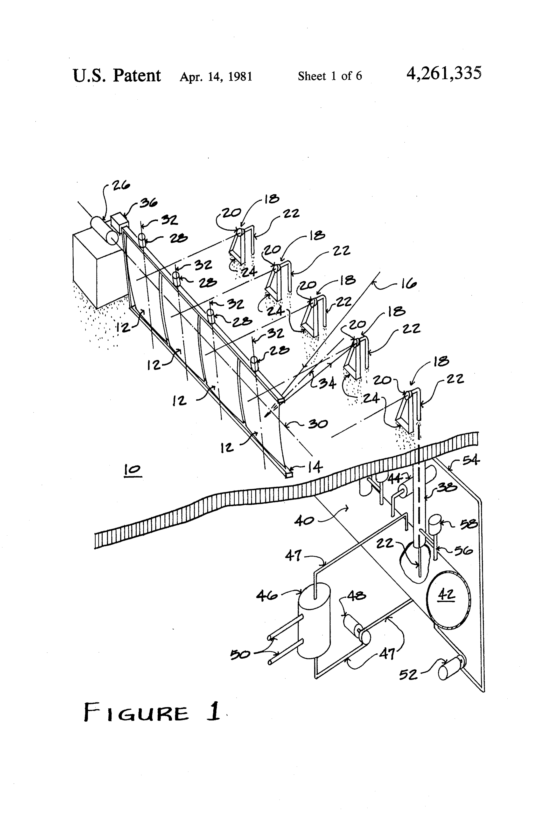
temperature range of the heat medium and by the prin 35 BRIEF DESCRIPTION OF THE DRAWING ciples of heat transfer mechanics. The use/storage appa ratus cannot achieve temperatures any greater than the FIG. 1 is a fragmentary perspective illustration of a temperature of the heat transfer medium. preferred embodiment of the solar energy apparatus of Fourth, energy is consumed in continuously circulat the present invention.
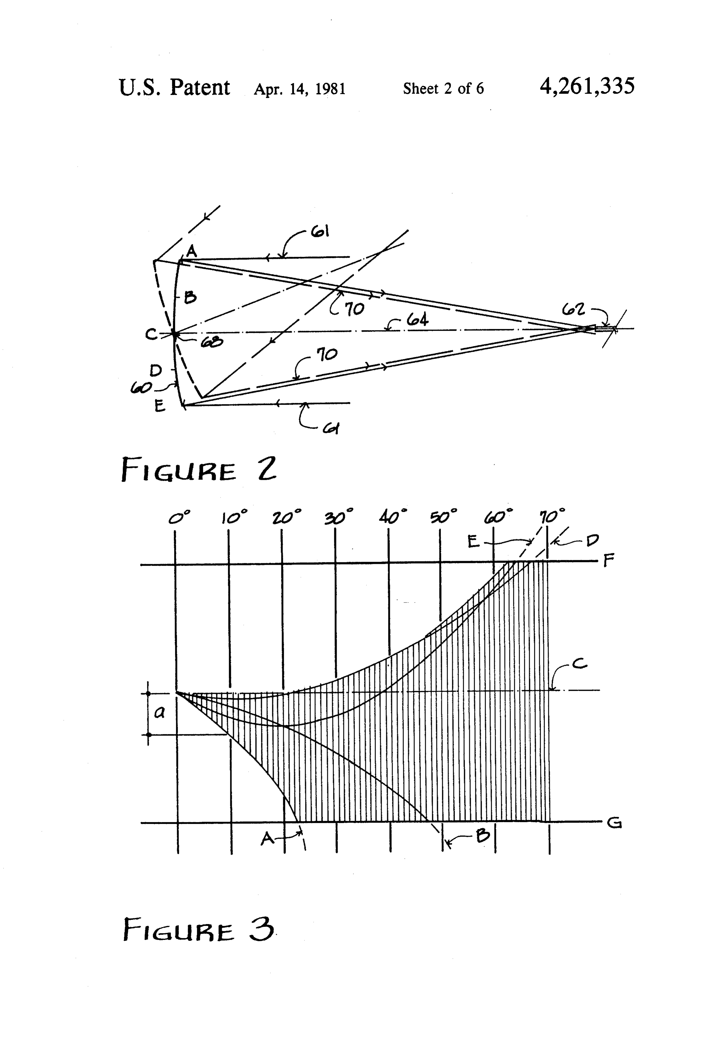
ing the heat transfer medium between the absorber and FIG. 2 is a diagrammatic illustration of the reflected the use/storage apparatus. rays of solar radiation by a tracking parabolic reflector U.S. Pat. No. 3,905,352 by Jahn shows a prior art with the pivot point of the reflector at the apex of the Solar energy apparatus which utilizes an array of mov parabolic curvature. , able flat reflectors to concentrate solar radiation on a FIG.3 is a chart of the pattern of reflected rays on the solar boiler, absorber tube, or similar apparatus. This receiver from selected points A, B, C, D and E on the prior art apparatus requires absorber areas equal in size reflector of FIG. 2 through 70 degrees of rotation of the to the area of the individual reflector, regardless offield sun away from the receiver.
size or focal distance. In addition, it requires a complex FIG. 4 is a diagrammatic illustration of the reflected apparatus for moving the various flat mirrors.
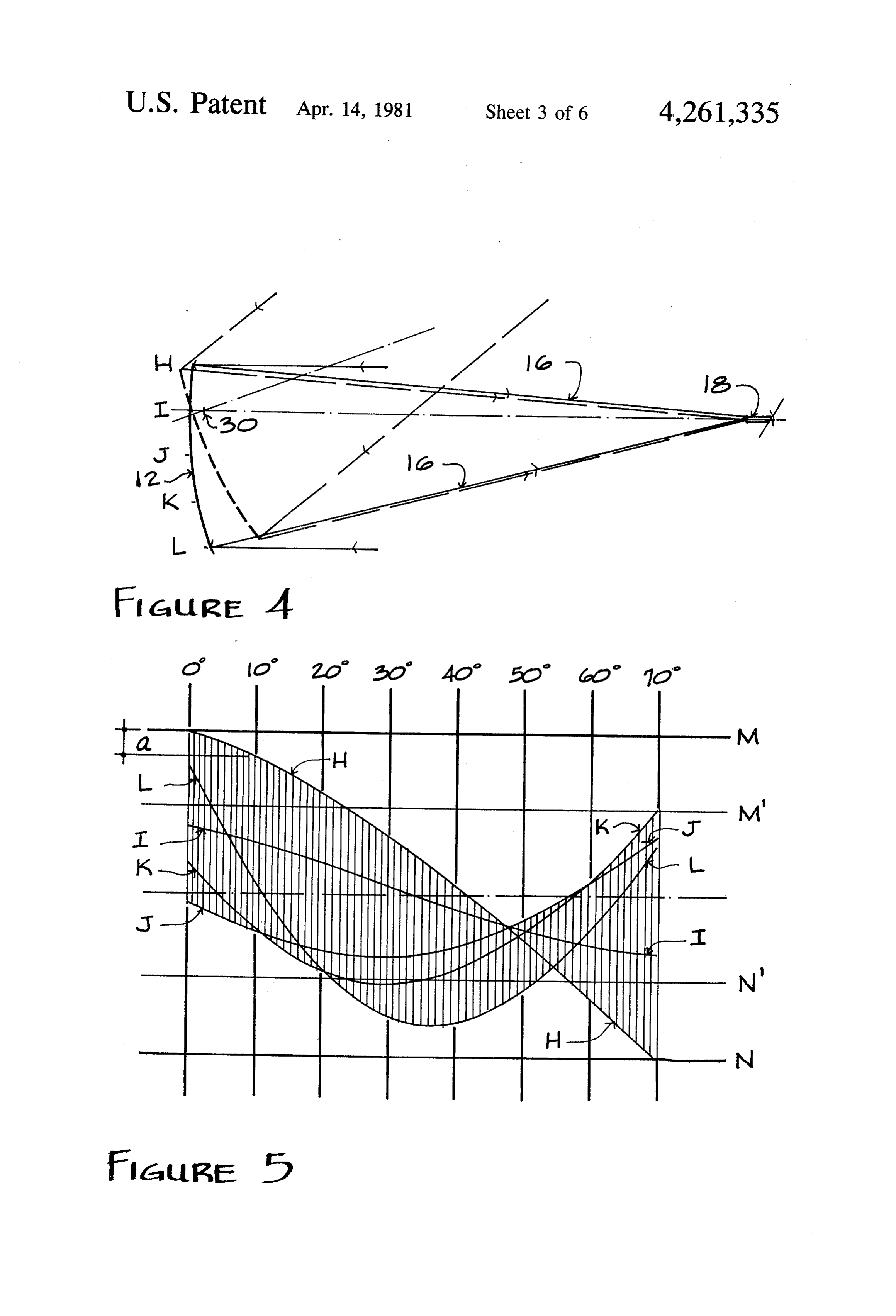
Prior art solar energy apparatus have also used 50 rays of solar radiation by an aspheric reflector of the aspheric reflectors rather than flat mirrors like those preferred embodiment for the vertical section of the shown in the Jahn patent. These aspheric reflectors are present invention, with the pivot axis of the reflector capable of concentrating solar radiation at a focal line forward of the reflector surface.
or focal point of the reflector. The focal line or focal FIG. 5 is a chart of the pattern of reflected rays on the receiver from selected points H, I, J, K and L on the point, however, must remain in the same position rela 55 reflector tive to the reflector. * ,, of FIG. 4 through 70 degrees of elevation of Another type of prior art solar energy apparatus uses the sun away from the receiver.
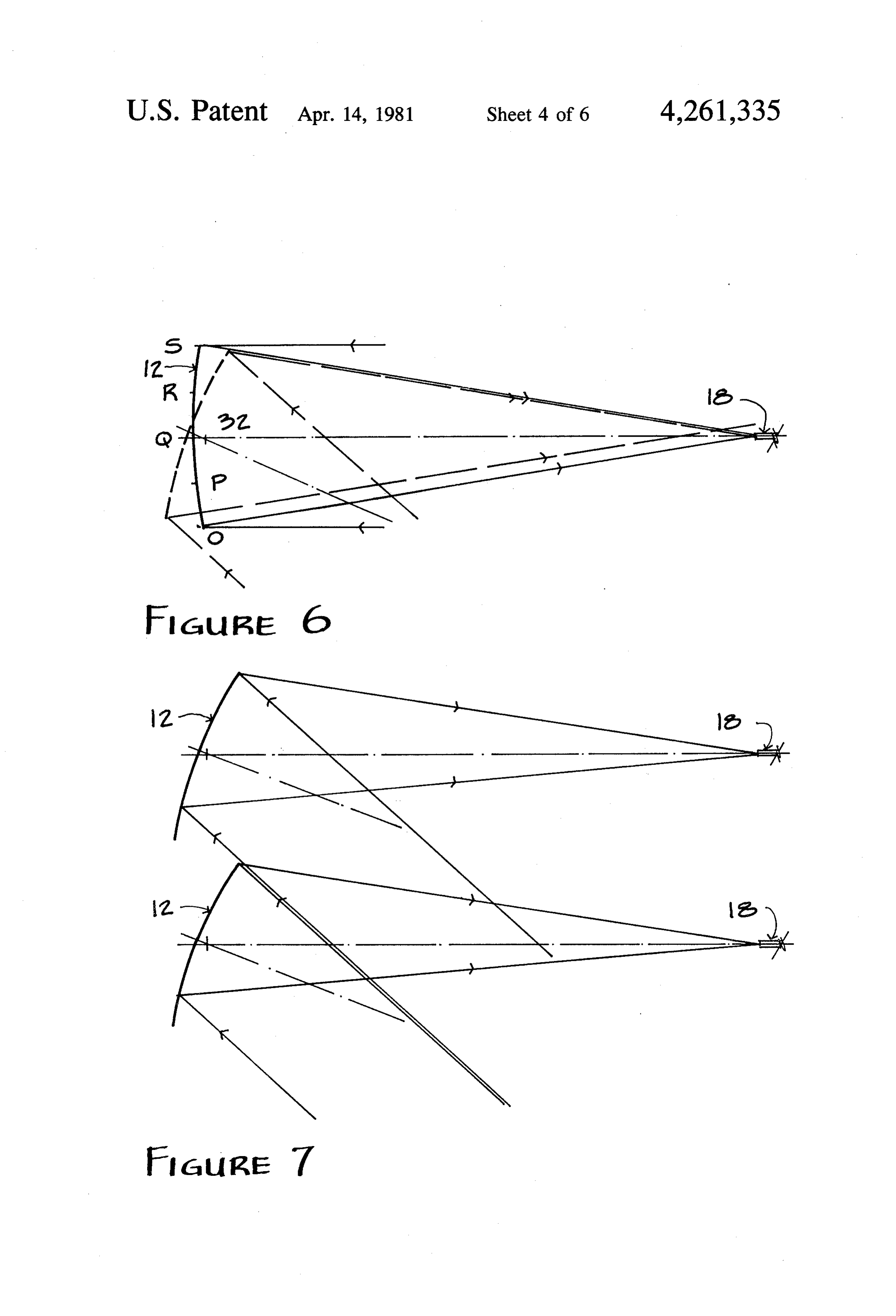
optical waveguides, typically in the form of fiber optic FIG. 6 is a diagrammatic illustration of the reflected bundles, to collect and transmit solar radiation. U.S. rays of solar radiation by an aspheric reflector of the Pat. Nos. 3,467,840 by Weiner; 3,780,722 by Swet; preferred embodiment of the plan section of the present 4,026,267 by Coleman; and 4,029,519 by Schertz et al. invention, with the pivot axis forward of the reflector describe solar energy apparatus using optical wave surface. . .
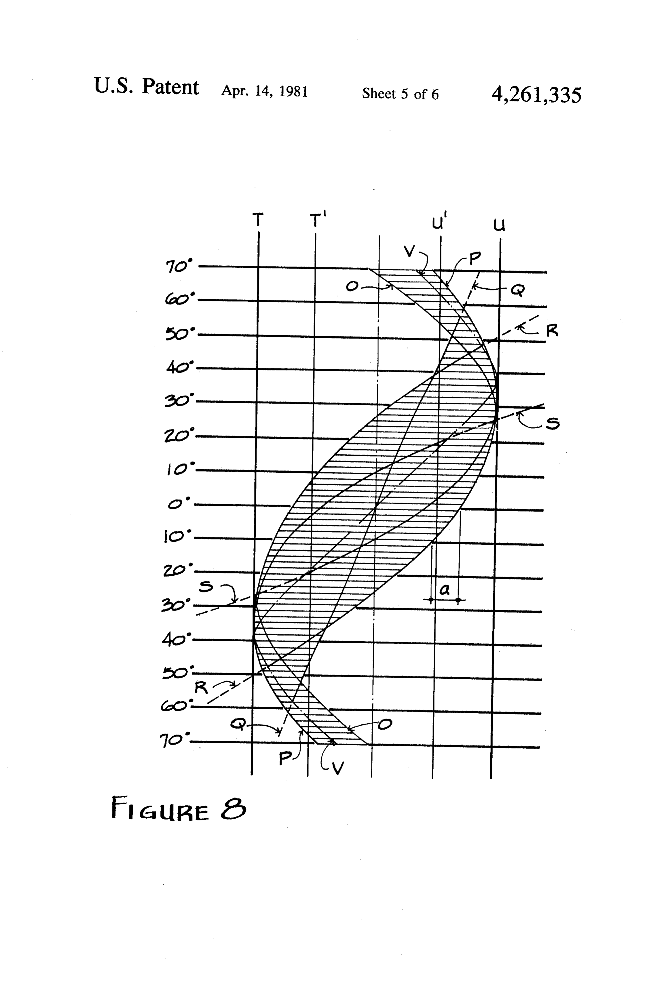
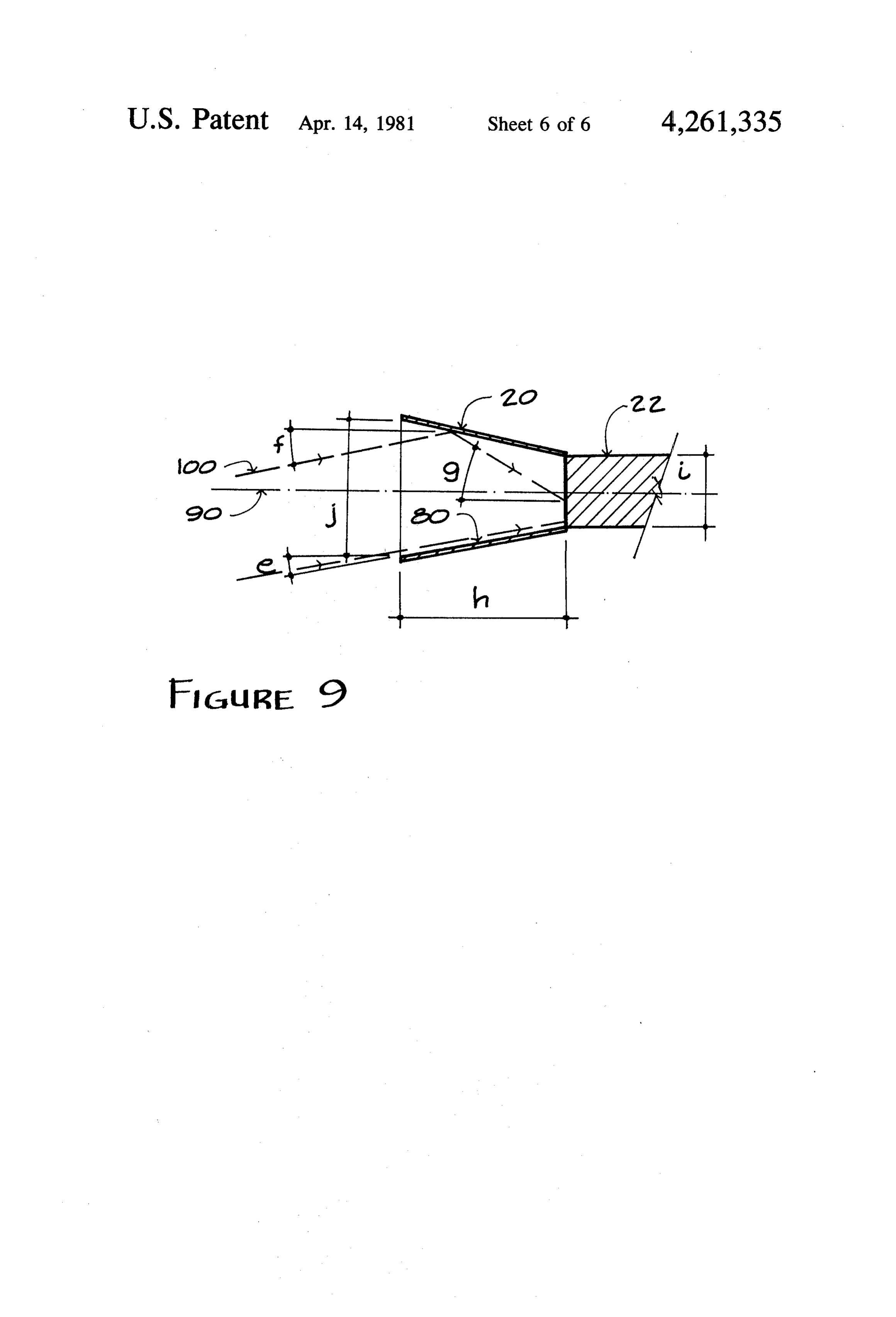
guides. : FIG. 7 is a diagrammatic illustration of adjacent re One difficulty of the prior art solar energy apparatus flectors of the preferred embodiment of the present using optical waveguides is that the optical waveguides 65 invention, and the resultant shading of adjacent reflec typically accept radiation only from a relatively small tors at large angles between the sun and the receiver. angle of incidence. Since the sun's position in the sky. FIG. 8 is a chart of the pattern of reflected rays on the changes throughout the day, this significantly reduces receiver from selected points O, P, Q, R and S on the 9 reflectors of FIGS. 6 and 7 from 70 degrees east of solar In the preferred embodiment of the present invention noon, to solar noon, to 70 degrees west of solar noon. shown in FIG. 1, altitude adjusting means 26 includes FIG. 9 is a diagrammatic illustration of a preferred an electrical motor which is driven by electrical signals embodiment of a secondary concentrator. from control 36. Similarly, azimuth adjusting means 28 DETAILED DESCRIPTION OF THE is shown in FIG. 1 as individual motors controlled by PREFERRED EMBODIMENTS control 36 which pivot each of the reflectors 12 about their respective vertical axes 32. Alternatively, a single
The Solar Energy Apparatus of FIG. 1 motor may drive reflectors 12 about their respective The preferred embodiment of the present invention vertical axes 32 through an appropriate mechanical illustrated in FIG. 1 overcomes many of the problems 10 linkage (not shown).
Altitude adjusting means 28 also preferably inverts which have limited the effectiveness of prior art solar apparatus. The apparatus includes a highly efficient the reflector supporting frame 14, together with reflec system for collecting and concentrating solar energy ergy 12, tors at night and at other times when the solar en and for transferring that solar energy to a location 5 duringapparatus is not in use. This protects reflectors 12 non-operating periods.
within a building or enclosure for conversion to thermal In one preferred embodiment of the present inven energy.
tion, optical waveguide rods 22 have a vacuum depos
As shown in FIG. 1, the solar energy apparatus of the ited, antireflection coating on their solar radiation re present invention includes an energy collection and ceiving first ends. This coating increases the percentage concentration subsystem which collectors and concen 20 of concentrated solar radiation internalized by optical trates the solar energy and which is mounted on a roof waveguide rods 22 from approximately 90% to approxi deck 10 or similar surface. The apparatus of the present mately 98%.
invention also includes a subsystem which converts the In one preferred embodiment, optical waveguide solar energy which has been collected and concentrated rods to thermal energy. This subsystem is located with the 25 lected22forareitsformed ability of a 96% silica glass, which is se to transmit light efficiently and for building or other enclosure. In FIG. 1, roof 10 has been its long term stability under exposure to high concentra broken away to show a portion of the solar energy tions of ultra-violet wavelength portions of solar radia conversion subsystem. tion. Optical waveguide rods 22 of the preferred em The solar energy collection and concentration sub bodiment are approximately 1.50 inches in diameter to system includes an array of aspheric reflectors 12, 30 receive solar radiation reflected directly to optical which are pivotally mounted in reflector support frame waveguide rods 22 by the primary aspheric reflectors 12
Incident solar radiation rays 16 strike each reflector or reflected to rods 22 by secondary concentrators 20. As shown in FIG. 1, each optical waveguide rod 12 and are reflected to a fixed first position 18 associated passes with each reflector 12. Located at each fixed first posi 35 38 andthrough an opening in roof 10, through a shroud tion 18 are a secondary concentrator 20 and the first end second end of rod conversion into a light reservoir or tank 40. The 22 extends into the interior of reser of optical waveguide rod 22. The secondary concentra voir 40 and is immersed in a use/storage medium 42 tor 20 is positioned forward of the first end of optical contained within reservoir 40. waveguide rod 22, and both secondary concentrator 20 Light transmitted by optical waveguide rods 22 im and waveguide rod 22 are supported by a support 24 at pringes upon the use/storage medium 42 and is con the fixed first position 18.
Because the sun's position with respect to roof 10 use/storage medium 42, expansionstorage verted to heat. The insulated tank reservoir 40, and piping 44, changes during the sunlight hours, altitude adjusting heat exchanger 46, piping 47, pump and controls 48, and means 26 and azimuth adjusting means 28 change the use system piping 50 are all located within the building positions of the aspheric reflectors 12 to maintain the 45 enclosure.
concentrated solar radiation on the ends of optical In a preferred embodiment of the present invention, waveguide rods 22. Altitude adjusting means 28 pivots use/storage reflector supporting frame 14 about horizontal pivot HT43, whichmedium 42 is an oil medium of Caloria is selected for its temperature range of up axis 30, thereby pivoting all of the reflectors 12 by an to 375 F. and its comparative low cost. The cost of equal amount. Azimuth adjusting means 28 adjust the 50 filling reservoir tank 40 with a large volume of fluid is respective mirrors 12 about vertical pivot axes 32. further reduced by partially filling reservoir 40 with In the preferred embodiment shown in FIG. 1, each rocks. The oil/rock storage medium 42 provides a reflector 12 is pivoted about axes 30 and 32 to maintain somewhat greater thermal capacity than all oil. its focal axis 34 at a half angle position between the sun The fluid use/storage medium 42 is circulated be and the fixed first position associated with that particu 55 tween reservoir 40 and heat exchanger 46 through pip lar aspheric reflector during a majority of the hours of ing 47 and pump 48. Heat is extracted from the medium sunlight. The operation of altitude adjusting means 26 42 within heat exchanger 46, and this heat is transferred and azimuth adjusting means 28 is controlled by control to the desired end use by piping 50.
36, which supplies control signals which determine the In the preferred embodiment of the present invention, desired location of each reflector 12 about both hori 60 the optical immersion of the ends of optical waveguide zontal axis 30 and its vertical axis 32. In one preferred rods 22 in use/storage medium 42 permits high effi embodiment, control 36 is a microcomputer which has ciency transfer of the solar radiation to the use/storage stored in memory the desired positions of reflectors 12 medium 42. A special optical coating on the second as a function of time for each day of operation. This ends of rods 22 is typically not required. form of control is an open loop control, since it does not Although a significant portion of solar radiation re depend upon sensing of the sun's position, but rather is ceived on the first ends of optical waveguide rods 22 is determined by stored information within the memory of transmitted to the second ends of rods 22 and into me microcomputer 36. dium 42, a second portion of solar radiation is converted 10 to heat along the length of the optical waveguide rods FIG. 3 is a chart which shows the relative distance a 22. This conversion to heat is the result of light trans from the zero angle focal point of the reflected rays 70 mission losses within optical waveguide rods 22. In the of the points A to C of the reflector 60 surface through preferred embodiment of the present invention shown 70 degrees of angular rotation between the sun and the in FIG. 1, an active heat transfer system is also included. fixed receiver 62 as computed by the equation: This active heat transfer system includes shrouds 38, which surround rods 22 from the inner surface of roof 10 to reservoir 40. Use/storage medium 42 is circulated a = b (1 - cos b + b sg.) by pump 52 and piping 54 and 56 from tank 40 through shroud 38 and back to tank 40. Flow control 58 controls 10 and of points C to E as computed by the equation: the flow of the circulating medium 42. The circulating use/storage medium 42 collects heat generated by opti b sin b cal transmission losses in optical waveguide rods 22 and a = -b (1 - cos d - C ) transfers it to reservoir 40.
Preferred Embodiment of the Aspheric Reflectors 12 where:
In the preferred embodiments of the present inven b= distance of the reflecting point from point C on the reflector 60 surface.
tion, the aspheric reflectors 12 are oriented with respect c=focal length of reflector 60. to pivot axes 30 and 32 so that the reflector surface of db=one-half the angle between the sun and the re reflectors 12 are located rearward of the pivot axes. In 20 ceiver 62.
addition, those segments of each reflector that advance toward the fixed location of the first end of waveguide doFor not purposes of simplification, the above equations incorporate the minor effect of the curvature of rod 22 are effectively greater in width than those seg the reflector 60, representing instead, values from a flat ments which retreat from the fixed position of the first 25 plane of parabolically tilted, infinitely numerous seg end. Also, each point of the reflector 12 surfaces is tilted ments.
with the total travel of the reflected rays 16 from that As shown in FIG. 3, a parabolic reflector 60 does not point at the fixed first position 18 centered on the fixed provide the limited pattern of reflected light preferred first position 18. This unique configuration provides for the present greater concentrating efficiency in directing the solar 30 gles between theinvention through sufficiently wide an radiation to the fixed first position 18 of the first ends of limits of 21 mrad from line F receiver sun and the 62. The preferred to G are shown in FIG. 3. .
optical waveguide rods 22.
To appreciate the advantages of this unique reflector focalIt is computed that a parabolic reflector of a size and configuration, a consideration of pivoted parabolic re provide length for the presently preferred invention would flectors, and their limitations in concentrating solar 35 at an angle a pattern or reflected light exceeding 21 mrad radiation onto a fixed receiver is of interest. FIGS. 2 of approximately 23 degrees between the sun and 3 describe the operation of a pivoted parabolic and the receiver, and would provide an even larger pattern at greater angles.
reflector 60.
The preferred embodiment of the present invention
In the following discussion, one criterion of reflector provides performance will be that the focused radiation will fall an aspheric reflector 12 having a different within a 21 mrad angular dimension limit from the re configuration in the vertical cross section than in the flector 2, which is the aperature width of the second horizontal or plan cross section. As a result, a significant ary concentrators 20. This requirement is necessary reduction radiation in the size of the pattern of reflected solar is achieved.
since optical waveguide rod 22 accepts incident radia FIG. 4 shows the vertical cross section of the reflec tion only within a restricted cone of incidence and the 45 aperture width of the secondary concentrators 20 is tor 12. Reflector 12 is an aspheric, nearly parabolic limited by the cone of incidence and the diameter of the rays reflector, that is advantageously configured to reflect optical waveguide rods 22 to 21 mrad. Since the major 16 from each point on the surface of the reflector consideration is to direct as much radiation as possible 12 to the receiver within the preferred angular distance into rods 22, the limitation on angular dimension is of 50 of 21 mrad through at least 70 degrees of angle between the sun and the receiver. As shown in FIG. 4, reflector major importance. The angular dimension of the ends of optical waveguide rods 22 is 11 mrad. 12 has a greater portion that advances toward the re Parabolic reflector 60 focuses the rays 61 of solar ceiver (i.e. secondary concentrator 20 and rod 22) at radiation to a common point at receiver 62 on its focal fixed first position 18 than retreats from the receiver. Horizontal reflector pivot axis 30 is located forward of axis 64 when the solar rays 61 are parallel to the focal 55 the axis 64 as shown in solid lines in FIG. 2. As the para reflector surface.
bolic reflector 60 is rotated about an axis 68 through the The modified equations that encompass the combined apex of the parabolic curvature to maintain a half angle advantages of the configuration of reflector 12 are: position between the sun and the fixed receiver 62, the reflected rays 70 from the A to C portion of the reflec a = b (1 - cos d) -- d sin db + tor 60 moving away from the receiver 62, strike the receiver 62 at increasingly further distances from the
Zero angle focal point as the angle between the sun and for points of the reflector 12 from H to I and the fixed receiver 62 increases. Rays 70 reflected from point C remain focused on the same point on the re 65 ceiver 62. However, rays 70 reflected from the C to E a = -b (1 - cos d) + d sin (b. -- b (b sin d -- d(1 portion diverge from the zero angle focal point in a more erratic pattern. for points on the reflector 12 from i to L where:
Page 11scan →
b = distance of reflecting point from point I on the of 11 mrad and is the preferred width of the optical reflector 12 surface. waveguide rods 22 as shown in FIG. 1. Through the c=focal length of reflector 12. preferred angles of zero degrees to at least 70 degrees d=distance from reflector 12 surface to pivot point between the sun and the receiver, the portion of the 30. concentrated solar radiation focused between T and U' db=one-half the angle between the sun and the re is focused directly on the optical waveguide rods 22 ceiver without an additional reflectance light loss. As before, the above equations do not incorporate the The equations for a are the same as stated above for minor effect of the curvature of reflector 12. the vertical cross section of reflector 12, wherein the The advantageously configured curvature of reflec first equation determines a for points on the reflector 12 tor 12 purposely does not focus all reflected rays 16 to rotating away from the receiver, either left or right, and a common focal point when the angle between the sun the second equation determines a for points on the re and the receiver is zero, as a true parabolic reflector flector does. The curvature is adjusted such that the total tra right. 12 advancing towards the receiver, either left or versed pattern of reflected solar radiation from each 15 The shading of one reflector 12 by the adjacent re point on the reflector 12 surface is centered on the re flector 12 results in a reduction of the effective area of ceiver at fixed first position 18, as is shown in FIG. 5, a row of reflectors as the angle between the sun and the from the preferred angles of zero degrees to at least 70 receiver increases. The reduction occurs as a cosine degrees between the sun and fixed first position 18, and function of the angle, and is the same as the reduction in is within the preferred limit of 21 mrad as shown by 20 other collector configurations such as fixed collectors lines M and N.
The forward horizontal pivot axis 30 of reflector 12 sun to the spaced or closely tracking collectors, as the angle of the reduces the angular dimension of the pattern from the combination with plane common of the collectors decreases. In portion of the reflector 12 that advances toward the reflectors in the present invention,configuration the aspheric the shading of the reduces fixed first position 18 of the receiver, and is advanta 25 the reflected pattern of solar radiation to line V in FIG. geously utilized in the preferred embodiment with a 8.
reflector 12 that provides a major portion of its surface In one preferred embodiment of the collecting and advancing toward the receiver.
concentrating means of the present invention, the re
The preferred limit of 21 mrad of angular dimension flector shown in FIG. 5 by lines M and N is the aperture width 30 F.G. 124 dimensions are as follows: of the secondary concentrator 20 as shown in FIG. 1. H to I-8 inches
M' to N' of FIG. 5 is an angular dimension of 11 mrad I to L-40 inches and is the preferred width of the optical waveguide rod FIG. 6 22 as shown in FIG. 1. Through the preferred angles of zero degrees to at least 70 degrees between the sun and 35 O to Q-24 inches the fixed first position 18, a majority of the reflected Q to S-24 inches solar radiation is focused directly onto the optical These dimensions provide a reflector area of 48 inches waveguide rods 22, and only a small portion is reflected by 48 inches. The focal length c of this preferred exam by the secondary concentrators 20, wherein an addi ple is 136 inches, the dimension d between the pivot axis tional reflectance loss would be incurred. and the reflectors surface is 2 inches, and the distance The preferred embodiment of the horizontal or plan between the edges of the reflectors is 2 inches. The cross section of the reflectors 12, as shown in FIG. 6, collected and concentrated solar radiation from reflec also provides that vertical pivot axis 32 be located for tors 12 of this size is focused on secondary concentra ward of the reflector surface. Reflector 12 has equal tors 20 of 2.84 inches in width, which is 20.9 mrad of portions of its reflector surface on each side of vertical 45 angular width.
pivot axis 32, but in the preferred embodiment, shown It is known that the size, focal length, pivot offset in FIG. 7, one reflector 12 shades the portion of the distance and configuration of the reflectors may be adjacent reflector 12 that rotates away from its associ varied, independently or in combination, to affect the ated receiver, resulting in an effective reduction of the performance of the collecting and concentrating means. retreating reflector area. This effective reduction is 50 FIG. 9 shows a preferred embodiment of secondary similar in effect to the selection of the vertical cross concentrator 20, which is provided at the end of the section of the reflectors 12 in FIG. 4. The distance optical waveguide rod 22. Secondary concentrator 20 is between the reflectors 12 of FIG. 7 determines the conical in shape, and has a maximum angle e of 10 de extent of shading and is selected in the preferred em grees between the reflective surface 80 of the secondary bodiment to maximize the reflector area "seeing' the 55 concentrator 20 and the axis 90 of the optical wave sun without reflecting solar radiation to the receiver guide rod 22. Reflected solar rays 100 do not exceed an outside the preferred angular dimension of 21 mrad. angle f of more than 10 degrees and are reflected onto The preferred embodiment of the horizontal or plan the end of the optical waveguide rod 22 within an angle cross section of the reflectors 12, as shown in FIG. 6, g of about 30 degrees, the maximum allowable inci also provides the same centering of the total traversed 60 dence angle to the optical waveguide rod 22. pattern of reflected solar radiation from each point on The length h of secondary concentrator 20 is limited the unshaded portion on the reflector 12 surface on the to slightly less than 2.5 times the width i of optical receiver at fixed first position 18, as shown in FIG. 8. waveguide rod 22. In the preferred embodiment with The shading effect is shown by line V, and the reflected the example size of the presently preferred primary solar radiation is focused within the preferred limit of 21 65 reflectors given above, a secondary concentrator 20 mrad of angular dimension as shown by lines T and U, equal in size to the above-stated receiver size of 2.84 which is again the aperture width of the secondary inches across its opening j provides secondary concen concentrators 20. T to U' is again an angular dimension tration of the concentrated solar rays 100 to a width of
Page 12scan →
1.50 inches at optical waveguide rod 22, with a magnifi the second end of the optical waveguide means is im cation of over 1,300. mersed in the first use/storage medium. CONCLUSION 4. The solar energy apparatus of claim 1 and further comprising active heat transfer means for collecting,
The solar energy apparatus of the present invention 5 from the optical waveguide means, heat produced by improves upon prior art systems by providing a collec light transmission losses of a portion of the solar radia tor and concentrator of solar radiation with an effi tion in the optical waveguide means.
ciency of up to 80%. It does not require circulation of 5. The solar energy apparatus of claim 4 wherein the the heat transfer medium outside of the building enclo active heat transfer means includes shroud means sur sure and is capable of achieving extremely high temper 10 rounding at least a portion of the optical waveguide atures. The present invention consumes energy for the means, and means for circulating a second use/storage transmission of only a portion of the collected solar medium within the shroud means to collect heat from energy. the optical waveguide means. As described above, the present invention provides a 6. The solar energy apparatus of claim 4 wherein the tracking, aspheric reflector system which is capable of 15 first end of the optical waveguide means is exposed to concentrating radiation to a much smaller, fixed re an outdoor environment and the second end is not ex ceiver in substantially higher concentrations than has posed to an outdoor environment, and in which the heretofore been available through significantly large active heat transfer means is not exposed to the outdoor angles between the sun and the receiver. environment.
Although the present invention has been described 20 7. The solar energy apparatus of claim 1 wherein the with reference to preferred embodiments, workers receiver further includes:
skilled in the art will recognize that changes may be secondary concentrating means proximate the first made in form and detail without departing from the end of the optical waveguide means for receiving spirit and scope of the invention. solar radiation from the reflector means and con What I claim is: 25 centrating the solar radiation on the first end of the 1. A solar energy apparatus comprising: optical waveguide means.
a receiver including optical waveguide means having secondary 8. The solar energy apparatus of claim 7 wherein the a first end and a second end, the optical waveguide reflector fixedly concentrating means comprises a conical means transmitting solar radiation received at the 30 the located with respect to the first end of first end to the second end; optical waveguide means.
aspheric non-parabolic reflector means for concen conical 9. The solar energy apparatus of claim 8 wherein the trating solar radiation, the aspheric non-parabolic approximately reflector reflects solar radiation received within reflector means being pivoted for movement about the optical waveguide a 10' angle of its axis to the first end of first and second pivot axes forward of and proxi 35 30' angle of its axis. means within approximately a mate to an aspheric reflector surface of the 10. The solar energy apparatus of claim 1 wherein the aspheric reflector means, the aspheric reflector optical waveguide means comprises an optical wave surface having a segment which advances toward guide rod.
the receiver and a segment which retreats from the receiver as the aspheric reflector means is rotated the11.opticalThe solar energy apparatus of claim 10 wherein about the first axis, the segment which advances first end towaveguide rod has an optical coating on the having a greater effective width than the segment directed onto the first end. losses of solar radiation reduce reflection which retreats, an angular dimension of reflected 12. The solar energy apparatus of claim 1 wherein the solar radiation from the segment which advances preferred range of angles is between about 0' and about being reduced as the reflector means is rotated 45 70.
about the first axis, and wherein the aspheric reflec 13. In a solar energy apparatus which converts solar tor surface has a curvature which causes a total radiation to another form of energy, an improved appa pattern of reflected solar radiation from the reflec ratus for collecting and concentrating solar radiation at tor surface to be essentially centered on the re a receiver, the improved apparatus comprising: ceiver over a preferred range of angles between the 50 first aspheric non-parabolic reflector means for focus receiver and the sun; ing solar radiation, the first aspheric non-parabolic aximuth and altitude tracking means for rotating the reflector means having an aspheric reflector sur reflector means about the first axis and the second face having a curvature which causes a total tra axis to maintain the concentrated solar radiation versed pattern of reflected solar radiation from the proximate the receiver; and 55 reflector surface to be essentially centered on a light conversion means for receiving the solar radia receiver over a preferred range of angles between tion from the second end of the optical waveguide the receiver and the sun;
means and converting the solar radiation to useful azimuth and altitude tracking means for pivoting the work. first aspheric reflector means about first and second 2. The solar energy apparatus of claim 1 wherein the 60 axes to maintain the concentrated solar radiation light conversion means comprises: proximate the receiver; and a first use/storage medium; wherein the first aspheric reflector means has a seg first heat storage reservoir means for containing the ment which advances toward the receiver and a first use/storage medium; and segment which retreats from the receiver when the first heat dispensing means for dispensing heat from 65 azimuth and altitude tracking means pivots the first the use/storage medium. aspheric reflector means about the first axis and has 3. The solar energy apparatus of claim 2 wherein the a segment which advances toward the receiver and first use/storage medium comprises a fluid, and wherein a segment which retreats from the receiver when 13 the azimuth and altitude tracking means pivots the 19. A solar energy apparatus for concentrating solar aspheric reflector about the second axis, the seg radiation and directing the concentrated solar radiation ment which advances toward the receiver having a to a plurality of receivers comprising: greater effective width than the segment which a plurality of non-parabolic aspheric reflectors for retreats from the receiver, and wherein the first concentrating solar radiation to the plurality of and second axes are positioned forward of and receivers wherein each aspheric reflector has an proximate to the reflector surface at positions aspheric reflective surface having a curvature which cause an angular dimension of reflected which causes a total traversed pattern of reflected solar radiation from the segment which advances solar radiation from the reflector surface to be to be reduced. essentially centered on one of the plurality of re 14. The solar energy apparatus of claim 13 wherein ceivers over a preferred range of angles between the preferred range of angles is between about 0 and the receiver and the sun; about 70'. azimuth and altitude tracking means for pivoting 15. The solar energy apparatus of claim 13 wherein 15 each of the aspheric reflectors about first and sec ond axes to maintain the solar radiation concen the reflector means does not focus all reflected rays to a trated by each aspheric reflector proximate one of common focal point. the plurality of receivers; and 16. The invention of claim 13 further comprising: wherein each aspheric reflector has a segment which second aspheric reflector means for concentrating advances toward the receiver and a segment which solar radiation; 20 retreats from the receiver as the aspheric reflector wherein the azimuth and altitude tracking means is pivoted about the first axis, and wherein the pivots the second aspheric reflector means about segment which advances toward the receiver has axes essentially parallel to the first and second axes greater effective width than the segment which to maintain the concentrated solar radiation from retreats from the receiver. the second aspheric reflector means proximate a 25 20. The solar energy apparatus of claim 19 and fur second receiver; and ther comprising:
wherein the first and second aspheric reflector means a plurality of secondary concentrators, each second are positioned proximate one another and wherein ary concentrator positioned proximate one of the the second aspheric reflector means shades a por 30 receivers for receiving solar radiation from one of tion of the first aspheric reflector means from re the aspheric reflectors and concentrating the solar flecting solar radiation beyond a preferred angular radiation at the receiver. dimension. 21. The solar energy apparatus of claim 19 and fur 17. The invention of claim 13 and further comprising: ther comprising:
secondary concentrating means proximate the re 35 light transmission means having a receiving end posi ceiver for receiving solar radiation from the first tioned at each of the receivers, the light transmis aspheric reflector means and concentrating the sion means transmitting solar radiation received at solar radiation. w the receivers to second positions; and light conversion means for receiving solar radiation 18. The invention of claim 17 wherein the secondary at the second positions and converting the solar concentrating means comprises a conical reflector 40 radiation to thermal energy. fixedly located with respect to the receiver. k . . . .
Provenance
- Collection
- Patents citing this work
- Pages
- 13
- Method
- pdftotext (the PDF's own text layer) + pdftoppm 300dpi page scans
- Patent office record
- patents.google.com →
- Source
- Google Patents citing-documents table
- Assignee
- Balhorn Alan C
- Published
- 1981-04-14
- Transcribed from
- patentimages.storage.googleapis.com →