

patent · US4271823A
Unitary solar collector panel
9 June 1981
Text
Page 1bibliographic recordscan →
United States Patent (19)
Erb
(54) UNITARY SOLAR COLLECTOR PANEL
Inventor: Robert A. Erb, Valley Forge, Pa.
Assignee: The Franklin Institute, Philadelphia,
Related U.S. Application Data
Int. Cl.................................................. F24J 3/02 52 U.S.C. .................................... 126/445; 126/441;
3,239,000 3/1966 Meagher .......... ... 126/448 3,981,294 9/1976 Deminet et al. . ... 126/445 4,018,211 4/1977 Barr...................................... 126/439 4,062,352 12/1977 Lesk ..... ... 126/445 4,078,548 3/1978 Kapany ... 126/44 4,114,597 9/1978 Erb ....................................... 126/901 4,178,914 12/1979 Erb ....................................... 126/449
FOREIGN PATENT DOCUMENTS
Primary Examiner-James C. Yeung
Attorney, Agent, or Firm-Weiser, Stapler & Spivak
An improved unitary, coextruded solar collector panel of the type having an upper, heat insulating region, and a lower, heat absorbing region, each region having ribs which separate the region into channels, for the passage of a fluid therethrough, wherein the heat insulating region is provided with an increased number of chan nels, to decrease radiation and convection losses from the heat insulating region, and the heat absorbing region is provided with oblique ribs which form channels of increased cross sectional area, to improve heat transfer from the heat absorbing region to the fluid circulated therein. Bowing of the unitary collector panel out of its planar configuration is reduced by providing a heat absorbing region which is darkened in a manner such that the heat density is greatest at a point away from the bottom of the collector panel.
40 Claims, 8 Drawing Figures
Drawings
Page 2drawing sheetscan →
Page 3drawing sheetscan →
Page 4drawing sheetscan →
Page 5drawing sheetscan →
Page 6scan →
also capable of being produced in large sizes and quanti
UNITARY SOLAR COLLECTOR PANEL ties, decreasing both the cost of such units as well as the costs of installation and labor.
This application is a continuation-in-part of my co Although the unitary solar collector panels above pending application, Ser. No. 645,648, filed Dec. 31, described are well suited to solving the problems pres 1975, U.S. Pat. No. 4,114,597. ented in converting solar energy into heat, it has been BACKGROUND OF THE INVENTION found that certain aspects of those collector panels are capable of improvement, further enhancing the utility
This invention relates generally to the field of solar and potential for public acceptance of the resulting solar energy collection systems and in particular to an im 10 energy collection system.
proved unitary coextruded solar collector panel of the One such aspect concerns the particular nature and type having an upper, heat insulating region, and a configuration of the ribs used to separate the heat insu lower, heat absorbing region. lating region and the heat absorbing region into chan Recent realizations that alternative energy sources to nels through which a fluid may be uniformly maintained fossil fuels must be developed have caused substantial 15 or circulated.
efforts to be made in developing a commercially accept For example, it has been found that unitary collector able solar energy collection system. An essential com panels exhibit a certain degree of radiation and convec ponent of any solar energy collection system being the tion losses from the heat insulating region. These losses solar collector panel, a substantial amount of effort has can be reduced by suitably modifying the ribs used to been expended in the development of this element of the 20 form the channels of that region. system. Also, the heat absorbing region of such collector Initial efforts to develop a useful solar collector panel panels is capable of certain improvements. Modifica often resulted in heavy, cumbersome structures involv tions to the ribs which form that region can enhance ing the use of several, often incompatible, construction heat conduction from the heat absorbing region to the materials. This problem was particularly acute in the 25 fluid circulated therethrough, and can reduce the bow design of an acceptable flat plate type solar collector ing of collector panels out of their planar configuration, panel. which has been encountered in certain environments. The flat plate type collector panel is generally more compatible with large structures, such as homes or SUMMARY OF THE INVENTION offices, lending themselves well to the solar heating of 30 This invention relates generally to the field of solar air or water for use in the home or office, of water for energy collection systems, and in particular to an im distillation purposes, and even of water for use in heat proved unitary, coextruded solar collector panel of the ing a swimming pool. This compatibility results from type having an upper, heat insulating region, and a the existence on all buildings of large flat areas, such as lower, heat absorbing region, each region having ribs the roof or walls, upon which such flat plate type col 35 which separate both regions into channels, wherein the lector panels may be mounted. ribs are adapted to reduce radiation and convection Although well suited for use in connection with a losses from the heat insulating region, to increase con building, flat plate type collector panels had not yet ductive heat transfer to a fluid circulating through the found wide commercial acceptance for various reasons. heat absorbing region, and to reduce the bowing en Moreover, the cost of producing an efficient and work countered when such solar collector panels are exposed able collector panel often far outweighed its return, to certain environments.
seriously limiting acceptance of such collectors by the In order to convert radiation from the sun into useful public. thermal solar energy, a building structure is provided My patent application, Ser. No. 645,648 now U.S. with a plurality of coextruded unitary solar collector Pat. No. 4,114,597, which is hereby incorporated by 45 panels. First, the panels are affixed to the building using reference herein, discloses a flat plate type solar collec a plurality of battens particularly suited for such pur tor panel which serves to eliminate the above-men pose. Next the collector panels are joined at each end by tioned drawbacks thus enabling production of a com headers which are then connected to a circulating sys mercially acceptable solar thermal energy collection tem capable of directing the converted solar energy system. This is accomplished by providing a solar col 50 produced toward a useful purpose. lector panel which is unitary in construction and which In accordance with the present invention, the ribs is capable of being produced in long, lightweight and which separate the heat insulating region into a plural continuous sections. In this manner entire portions of a ity of channels, capable of retaining therein an insulat structure may be covered with a series of such panels ing fluid, are proportioned so as to reduce the width thereby enabling the conversion of sufficient amounts of 55 and/or cross sectional area of the heat insulating chan solar thermal energy to provide for the heating needs of nels. In this manner, convection currents within the a COSle. channels are reduced by frictional damping, thereby The unitary collector panels disclosed are produced reducing convection losses.
by coextruding a selected combination of synthetic Several alternative embodiments are capable of pro thermoplastics into long panels having heat insulating 60 viding such a result. For example, the width of the and heat absorbing layers along their entire length. In channels may be reduced by providing the collector this manner the previously required combination of panel with an increased number of ribs, and therefore, construction materials is replaced by a single unit re channels. It is also possible to employ oblique ribs, quiring no individual construction or separate parts. thereby creating triangular channels having relatively The resulting units are lightweight which permits easy 65 small cross sectional areas. Combinations of these con installation and also permits large surface areas to be figurations are also possible.
completely utilized without requiring substantial shor Further, in accordance with the present invention, ing of the underlying structural members. The unit is the ribs which separate the heat absorbing region into a 7 plurality of channels capable of passing a fluid there planar configuration when it is subjected to varying through, for heating of the fluid, are obliquely oriented temperature excursions during use. and are proportioned to increase fluid flow through the It is another object of the present invention to pro channels of the heat absorbing region, thereby increas vide an improved unitary solar collector panel which ing heat transfer to that fluid, and the remainder of the has a heat absorbing region, the heat density of which is system. greatest at a point away from the botton of the collec This is accomplished by providing the heat absorbing tor panel, to thereby reduce bowing of the collector region with oblique ribs, the upper end of which are panel out of its normally planar configuration. separated from the upper wall of the heat absorbing These objects and others will become apparent to region by a linear portion which is connected between 10 those skilled in the art from the following disclosure of the oblique ribs and the upper wall. In this manner, the the preferred embodiment of the invention taken in cross sectional area of one group of channels of the heat conjunction with the drawings provided in which like absorbing region is increased relative to the cross sec reference characters refer to similar parts throughout tional area of the remaining group of channels. By so the several views provided, in which: doing, the flow in the larger group of channels is 15 matched to the flow through the smaller group of chan BRIEF DESCRIPTION OF THE DRAWINGS nels, in a manner to be more fully described below, FIG. 1 is a perspective view of a building structure which improves, and thus increases, fluid flow through which has been provided with a solar thermal energy the heat absorbing region. collection system comprising a plurality of improved Also, in accordance with the present invention, the solar collector panels which are in vertical, transverse ribs of the heat absorbing region are darkened in a man ner which places the point of greatest heat density away alignment broken with the structure, and which is partially away to show interior construction details;
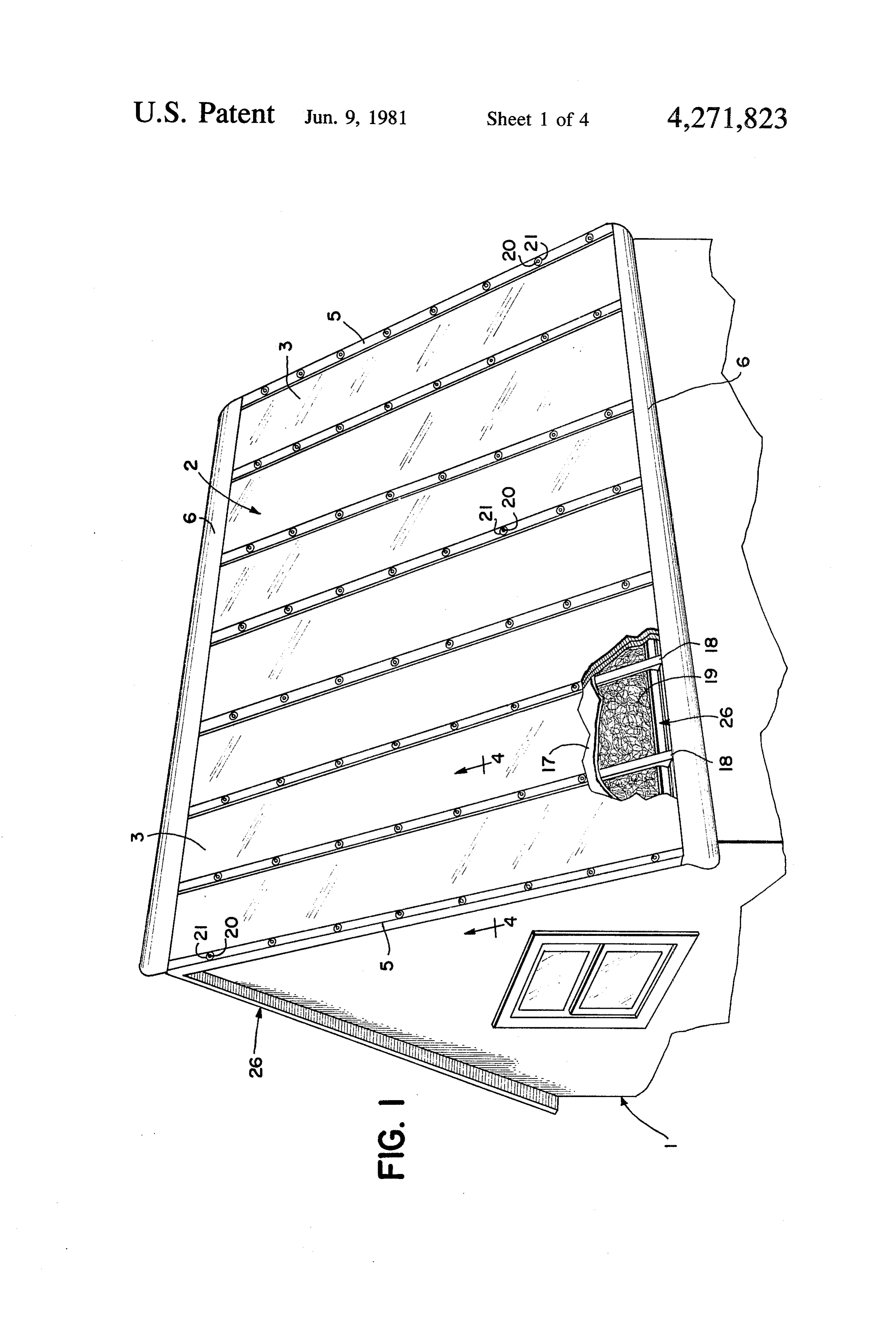
from the base of the collector panel, thereby reducing the potential for bowing of the collector panels out of which has beenperspective
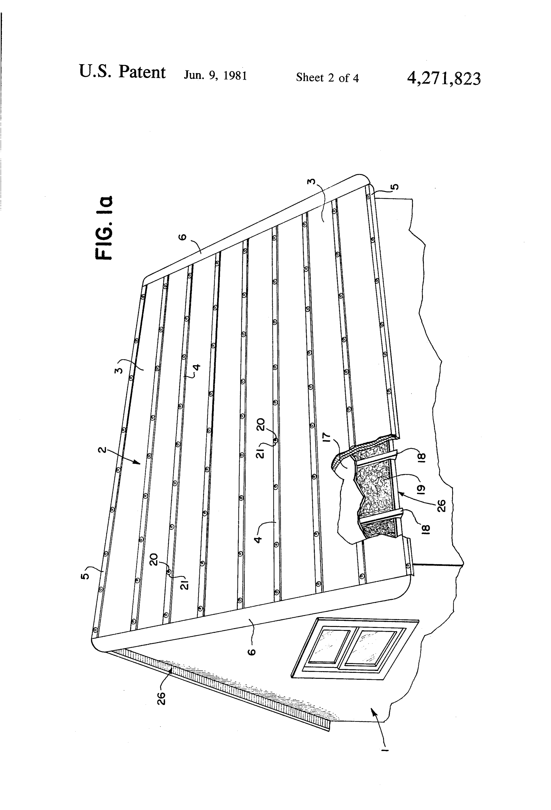
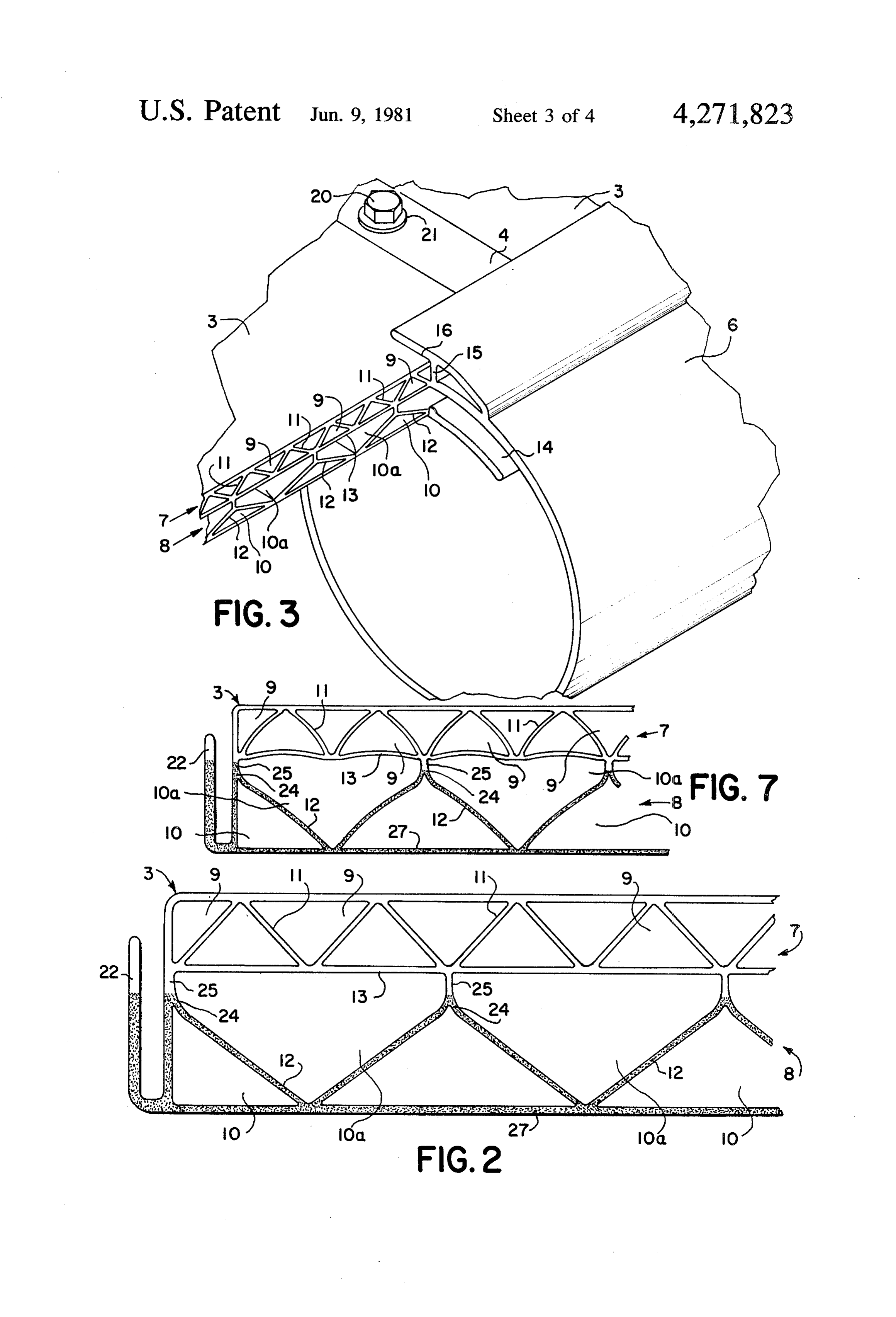
FIG. 1a is a view of a building structure their planar configuration as previously encountered in 25 collection system comprising a aplurality provided with solar thermal energy of improved certain environments. By appropriately darkening the solar ribs, rather than the bottom of the collector panel, the nal alignment with the structure, and which islongitudi collector panels which are in horizontal, partially point of greatest heat density is moved away from the broken away to show interior construction details; bottom of the collector panel, which reduces the expan FIG. 2 is a partial, cross sectional view of the pre sion differential between the clear and dark portions of 30 ferred embodiment of the improved unitary solar col the collector panel, thereby reducing the bowing which lector panel;
would result from such a differential.
It is therefore an object of the present invention to FIG. 3 is a partial, sectional view of the interface provide an improved unitary solar collector panel of between the collector panels, the header and the means increased efficiency. 35 for affixing the collector panels to the structure of the It is another object of the present invention to pro building;
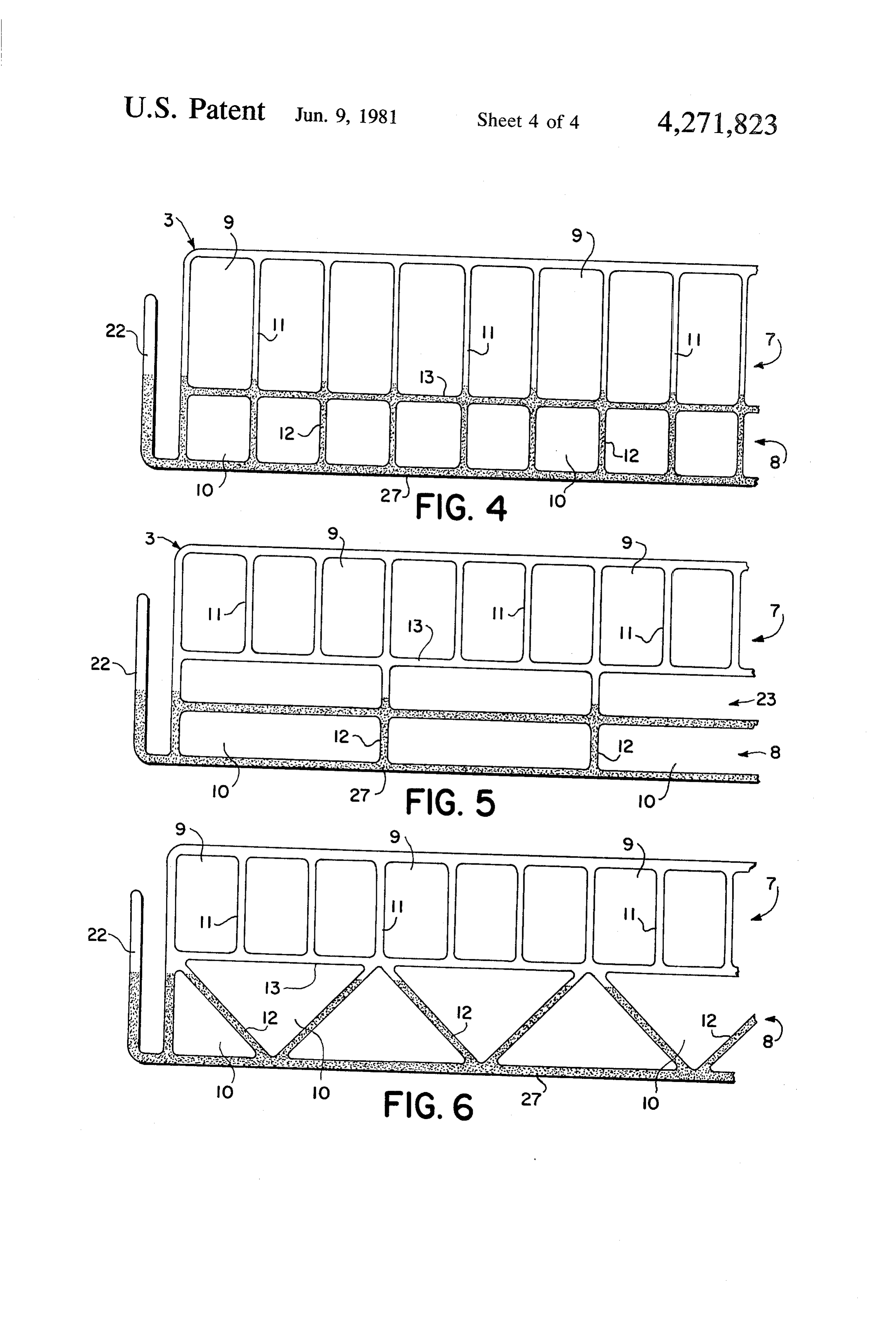
vide an improved unitary solar collector panel wherein FIG. 4 is a partial, cross-sectional view of a first, heat losses, due to radiation and convection, from the alternative embodiment of the improved unitary solar heat insulating region of the collector panel are re collector panel;
duced. 40 FIG. 5 is a partial, cross-sectional view of a second, It is another object of the present invention to pro alternative embodiment of the improved unitary solar vide an improved unitary solar collector panel wherein collector panel;
the heat insulating region of the collector panel has ribs FIG. 6 is a partial, cross-sectional view of a third, which are adapted to reduce convection through the alternative embodiment of the improved unitary solar heat insulating region. 45 collector panel; and
It is another object of the present invention to pro FIG. 7 is a partial, cross-sectional view of the im vide an improved unitary solar collector panel wherein proved unitary solar collector panel of FIG. 2 having the heat insulating region is provided with an increased curved ribs in the heat absorbing the heat insulating number of channels to thereby reduce convection region.
through the heat insulating region and the convective 50 DESCRIPTION OF THE PREFERRED heat losses which would result. EMBODIMENT OF THE INVENTION It is another object of the present invention to pro vide an improved unitary solar collector panel wherein Although specific terms are used in the following heat conduction from the heat absorbing region to the description for the sake of clarity, these terms are in fluid circulated therethrough is increased. 55 tended to refer only to the particular structure of the It is another object of the present invention to pro invention selected for illustration in the drawings, and vide an improved unitary solar collector panel wherein are not intended to define or limit the scope of the in the heat absorbing region of the collector panel has ribs vention.
which are adapted to increase flow of the conducting Referring now to the drawings, there is shown in fluid through the heat absorbing region. 60 FIG. 1 a building structure 1 which has been provided It is another object of the present invention to pro with a solar energy collector system 2. The solar energy vide an improved unitary solar collector panel wherein collector system 2 comprises a plurality of flat plate the heat absorbing region has channels of increased type solar collector panels 3 which are affixed to the cross sectional area to thereby increase fluid flow Structure 1 using a plurality of battens 4, 5, and a pair of through portions of the heat absorbing region. 65 headers 6 attached to the ends of the collector panels 3. It is another object of the present invention to pro The solar collector panels 3 would be generally of the vide an improved unitary solar collector panel which type disclosed in my patent application, Ser. No. resists bowing of the collector panel out of its normally 645,648; a unitary coextruded panel formed of synthetic 8 theremoplastic, having a heat insulating region 7 and a are used to affix adjacent panels 3 to each other and to heat absorbing region 8. the structure 1, or end battens 5 used to affix the outer Each solar collector panel 3 is provided with a heat edges of the outermost panels 3 to the structure 1 and to insulating region 7 and a heat absorbing region 8. The seal the edges of the roof 26 of the structure 1 from the heat insulating region 7 would be transparent and thus 5 outside elements.
capable of transmitting therethrough the major part of The collector panels 3 illustrated in FIG. 1 are affixed solar spectral radiation. The heat absorbing region 8 to the roof 26 in a transverse orientation, the headers 6 will be opaque, black or dark and thus capable of ab extending along the top and bottom of the roof 26. sorbing solar radiation passed through the heat insulat However, as illustrated in FIG. 1a, it is equally possible ing region 7. 10 to orient the collector panels 3 longitudinally, the head As illustrated in FIG. 3 each solar collector panel 3 is ers 6 extending along the edges of the roof 26 rather provided with a plurality of longitudinally, extending than along its top and bottom. Transverse placement of channels 9, 10, 10a defined by ribs 11, 12. The heat the collector panels 3 on the roof 26 is preferred to insulating region 7 and the heat absorbing region 8 are reduce the potential for water to collect along the seams separated from each other by a longitudinally extending 15 between the collector panels 3 and the battens 4, 5, and divider 13. Various fluids may then be provided within thus seep through the seams to the roof 26 below. the channels 9, 10, 10a to utilize the solar thermal en As illustrated in FIG. 1, the solar collector panels 3 ergy absorbed by the collector panels 3. For example, are preferably applied to the structure 1 over a substrate the heat insulating region 7 would generally be pro 17 formed of plywood, or other sheet material, which vided with air. By sealing the ends of the channels 9 20 may be conventionally applied to the rafters 18 of the forming the heat insulating region 7 the air is prevented roof 26 prior to installation of the collector panels 3. from circulating, thereby forming an insulating layer Insulation 19 may be applied beneath the substrate 17 between the heat absorbing region 8 and the outside and between the rafters 18 in known fashion. The solar elements. The heat absorbing region 8 would generally collector panels 3 may then be placed over the substrate be provided with a fluid such as air, a silicone fluid, 25 17 in juxtaposed relationship and retained in place by water or a water-ethylene glycol mixture, which is then the battens 4, 5, which are adapted to engage the collec circulated through the channels 10, 10a of the heat tor panels 3 along their edges and retain them to the absorbing region 8, thereby heating the fluid, which roof 26 of the structure 1. The battens 4, 5 may be at would then be carried away for use with the remainder tached to the substrate 17 and/or the rafters 18 using of the system (not shown). Of course, it is to be under- 30 any of several fastening means, for example, nails, stood that any one of several known fluids could be screws or the bolts 20 illustrated, placed at multiple utilized in connection with either the heat insulating locations along the battens 4, 5. Although not required, region 7 or the heat absorbing region 8 depending upon it is preferred that the fastening means be equally spaced the particular application involved. along the battens 4, 5. The bolts 20 may be provided Each end of the solar collector panel 3 would be 35 with flexible washers 21 in order to absorb some of the provided with a header 6 to permit connection of the stress produced when the bolts 20 are tightened and to collector panel 3 to the remainder of the heating system. prevent water leakage or seepage around the bolts 20. The headers 6 are preferably manufactured in a manner In this manner the collector panels 3 are securely similar to that of the collector panels 3, by extrusion of mounted to the roof 26 of the structure 1. a synthetic thermoplastic. Extrusion permits formation 40 Each solar collector panel 3 would advantageously of the headers 6 as long, unitary structures which may be on the order of 16 inches in width and would be of a quickly and easily be attached to the collector panels 3 length appropriate to cover the entire length or width along the entire length of the interface between those of a structure (e.g. 15-20 feet). A width of 16 inches is elements. . . . . advantageous in that many structures are provided with As illustrated in FIG. 3 the header is preferably, 45 rafters 18 having 16 inch centers. Thus a collector panel essentially circular in cross-section, although headers of 3 may be placed between and firmly attached to a pair other shapes may also be produced, and is provided of rafters 18. Of course, other widths are equally possi with an output channel 14, a fluid blocking portion 15 ble. Many homes presently have rafters 18 placed at 24 and a means for connecting the header 6 to the solar inch intervals. Collector panels having 24 inch widths collector panel 3. The fluid blocking portion 15 is pro- 50 would be appropriate in such cases. Although pre vided to prevent the fluid contained within the heat ferred, a one to one correspondence between rafter insulating region 7 from circulating, thus providing centers and collector panel width is not required, and insulation between the heat absorbing region 8 and the collector panels 3 having any appropriate width may be outside elements. The output channel 14 is adapted to utilized, if desired.
communicate with the channels 10, 10a of the heat 55 Collector panels 3 of the type above described are absorbing region 8 in a manner which improves the readily produced by the extrusion process, having uniformity of flow of the fluid as it flows between the widths preferably on the order of one to two feet. Such collector panels 3 and the headers 6, thus improving the panels may be produced in long sections, the length over-all efficiency of the system. As a means for con generally being limited only by convenience and bulk. necting the header 6 to the solar panels 3, the header 6 60 Fifteen foot sections have been found useful in many is provided with upper and lower brackets 16 which are applications, however other lengths are clearly possi adapted to overfit the collector panels 3 either friction ble. Several such panels 3 may be laid adjacent to each ally, by use of a suitable bonding agent, or by use of a other upon the roof 26 of the building structure 1, suitable mechanical means, e.g. blind rivets. In this man thereby enabling the complete coverage and usage of ner, the header 6 may be readily connected to one or 65 existing space.
more collector panels 3 as desired. After affixing the collector panels 3 to the roof 26th The solar collector panels 3 are affixed to the struc headers 6 may be attached to the ends of the collector ture 1 using a plurality of battens, either battens 4 which panels 3. The headers 6 may then be connected to the 9 remainder of the circulatory system as desired. The It has been determined that such currents could be above discussion illustrates the manner in which a plu appreciably reduced by increasing the frictional damp rality of solar collector panels 3 may be affixed to a ing between these currents and the walls of the channels structure 1 to combine to form a solar energy collection 9 of the heat insulating region 7. Such a result may be system 2. The collector panels 3 which combine to form obtained by providing an increased number of channels such a system 2 will now be described in greater detail. 9 in the heat insulating region 7, thereby reducing the FIG. 2 illustrates the preferred embodiment of the width and/or the cross sectional area of the channels 9, solar collector panel 3. As illustrated, the collector which increases the proportionate surface area of the panel 3 essentially comprises an upper, heat insulating walls contacted by a given current. region 7, and a lower, heat absorbing region 8, each of 10 FIG. 4 illustrates a first embodiment of a collector which is separated into a plurality of channels 9, 10, 10a panel 3 capable of producing such a result. In FIG. 4 adapted to accept fluids therein as will be further de there is shown a collector panel 3 which resembles in scribed below. many respects my earlier unitary collector panels. The collector panel 3 is particularly suitable for pro However, in this configuration there is one noteable duction as a unitary, coextruded panel, having no sepa 15 distinction: an increased number of channels 9 are uti rate parts, which serves to solve many of the problems lized per unit width in the upper, heat insulating region encountered with previous collector panels. Accord 7.
ingly, the heat insulating region 7 and the heat absorb In my application, Ser. No. 645,648, there is shown in ing region 8 may be formed as a unitary structure sepa FIG. 2 a unitary collector panel having twice as many rated by an integrally formed divider 13. channels in the heat absorbing region as are provided in To facilitate mounting the collector panel 3 to the the heat insulating region. Although such a configura building structure 1 an interlocking lip 22 may be pro tion provides excellent results, it has been found that a vided as part of the collector panel 3. The interlocking certain degree of heat loss is exhibited due to convec lip 22 is particularly adapted for use with the battens 4, 5 serving to provide a secure means of mounting the 25 tionIn currents in the heat insulating region. accordance with the present invention, the collec collector panels 3 to the roof 26. The battens 4, 5 are tor panel provided with corresponding means for engaging the channels 93 atis least provided with a number of heat insulating equal to the number of channels 10 of interlocking lip 22, forming an interlocking structure capable of providing adequate support for the collector each the heat absorbing region 8. In so doing, the width of panels 3. The interlocking lip 22 may advantageously be 30 channel 9 is decreased which increases frictional formed as an integral part of the collector panel 3, if damping between the walls of the channels 9 and the desired. currents circulating therein. In this manner heat loss due The collector panels 3 are preferably constructed of a to convection is decreased.
synthetic thermoplastic. Coextrusion of the panels 3 FIG. 4 shows a collector panel 3, provided with a permits their formation using either the same or differ 35 heat insulating region 7 and a heat absorbing region 8 ent materials for various sections of the collector panel having equal numbers of channels 9,10, which will ex 3, in particular the heat insulating region 7, and the heat hibit the above described insulating effect. Also to be noted in connection with the collector absorbing region 8. The heat insulating region would preferably be formed of a material which is transparent panel 3 of FIG. 4 is that, by decreasing the width of the or translucent in nature. The heat absorbing region 8 channels 9, those channels 9 are now rectangular in would generally be formed of a material which is form, having a height in excess of their width. Such a opaque, dark or black in nature. Such a structure is well configuration serves to further increase collector effi suited to the formation of long, lightweight, unitary ciency by increasing the space provided for trapping collector panels thus providing a significant advance in heat absorbed by the collector panel 3, thereby reduc the art. 45 ing radiation losses from the heat insulating region. Both the upper, heat insulating region 7, and the Although such a configuration is preferred, it is not lower, heat absorbing region 8, are divided into a plural required for proper execution of the foregoing inven ity of channels 9,10,10a, by ribs 11,12. The channels tive technique.
9,10,10a extend longitudinally through the collector The collector panel 3 illustrated therefore serves well panel 3 serving to guide and direct the fluids contained 50 to reduce convection currents within the channels 9 of therein through the collector panel 3 in a uniform flow, the heat absorbing region 7. It is, of course, to be under thus contributing to the efficiency of the system 2. stood that many configuration are possible which are In my application, Ser. No. 645,648, the unitary col capable of producing similar results. For example, the lector panels disclosed were provided with ribs which insulating effect above described may be further in preferably extended vertically, perpendicular to the 55 proved upon by further increasing the number of chan base of the collector panel, such vertical ribs being used nels 9 in the heat insulating region 7 with respect to in both the heat insulating and heat absorbing region. those in the heat absorbing region 8. Increasing the Although such a configuration serves well in convert number of channels 9 is readily accomplished by pro ing solar thermal energy into heat, it has since been viding an additional number of ribs 11 per unit width determined that a certain degree of heat absorbed during manufacture of the collector panel 3. FIG. 5 within the heat absorbing region was being lost as a illustrates one such configuration, having three times as result of convection currents which were present in the many channels 9 in its heat insulating region 7 as are upper, heat insulating region of such panels. These cur found in its heat absorbing region 8. Other ratios are rents are present even though the ends of the collector similarly possible.
panels 3 are sealed by the fluid blocking portion 15 of 65 The ribs 11 of the heat insulating region 7 and the ribs the header 6. Thus it became desirable to reduce such 12 of the heat absorbing region 8 are preferably formed losses by reducing the convection currents produced in in registration, as illustrated, to provide increased the heat insulating region 7. strength to the collector panel 3, however such registra 10 tion is not required for satisfactory results to be ob those areas. Since expansion occurs nearer the center of tained. the collector panel 3 the bowing which resulted from FIG. 2 illustrates another, preferred, configuration the uneven expansion previously encountered is re which may be used to decrease convection currents in duced.
the heat insulating region 7. In this configuration the FIG. 4 illustrates a first embodiment of a collector ribs 11 are oblique, forming triangularly shaped chan panel 3 capable of producing the above result. As previ nels 9 rather than the more conventional rectangular ously mentioned, the collector panels 3 are well adapted shape. The oblique ribs 11 serve to reduce the cross for manufacture by coextrusion of one or more syn sectional area of the channels 9 which form the heat thetic thermoplastics. During such manufacture the insulating region 7, thereby increasing the proportion 10 lower, heat absorbing region 8 is darkened using a suit ate surface area contacted by the fluid circulated able material, for example carbon black, to pigment the therein. Accordingly, as a result of frictional damping thermoplastic material used. By controlling the extent between the fluid and the walls of the channels 9, con of the area of the collector panel 3 that is so darkened vection currents are decreased. the point of greatest heat density may be readily moved Utilizing oblique ribs 11 serves to provide yet addi 15 to various points within the heat absorbing region 8 tional improvements. For example, the collector panel 3 which are away from the base 27 of the collector panel which results when oblique ribs 11 are used creates a 3. Thus, the collector panel 3 of FIG. 4 has been pro heat insulating region 7 having essentially two sub vided with a darkened area which surrounds the chan regions, one upon the other. In this manner those chan nels 10 of the heat absorbing region 8, extending nels 9, the base of which face upwardly, act as a first 20 through the divider 13 to a point just at the base of the insulating region, and those channels 9, having bases heat insulating region 7. The point of greatest heat den which face downwardly, act as a second insulating sity would therefore occur just below the divider 13 region between the outer, first region and the heat ab rather than at the base 27 of the collector panel 3, as is sorbing region 8. In this manner additional insulation is preferred.
provided reducing heat losses to the elements. 25 FIG. 5 illustrates an alternative embodiment of the Moreover, the triangular channels 9 not only serve to collector panel 3 of FIG. 4. In this configuration, the provide a heat insulating region 7 having two sub collector panel 3 is provided with a third, intermediate regions, but they also permit the formation of such region 23. The intermediate region 23 may be used to sub-regions in a collector panel 3 having essentially the provide either additional heat insulation, as previously same height as a collector panel 3 having only a single 30 mentioned, or may be used to provide additional surface heat insulating region 7. Such a configuration is clearly area for the transfer of heat absorbed by the collector advantageous for use in connection with a collector panel 3 to the fluid circulated therethrough. For exam panel 3 which will be visible, as a physical part of a ple, the intermediate region 23 illustrated is provided structure, where large, bulky collector panels 3 would with a darkened portion which extends approximately be undesirable. - 35 half-way into the intermediate region 23. The interme The above configurations therefore serve to signifi diate region 23 would then be well suited for operation cantly improve collector efficiency by reducing heat as a heat absorbing region, a suitable fluid being passed losses due to convection currents produced in the heat therethrough, for heat transfer to the remainder of the insulating region 7. By reducing heat lost to the ele solar thermal energy collection system (not shown). ments it naturally follows that additional heat will be Again the point of greatest heat density would be lo absorbed and retained witin the heat absorbing region 8, cated away from the base 27, at a point near the top of for subsequent use with the remainder of the system the heat absorbing region 8.
(not shown). Thus two further considerations directly In addition to reducing bowing, it may be seen that follow; how to effectively transfer heat absorbed by the the collector panel 3 of FIG. 5 also serves to increase heat absorbing region 8 to the fluid circulating there 45 the transfer of heat absorbed by the collector panel 3 to through, and how to prevent the heat retained by the the fluid circulated therethrough, thus addressing the heat absorbing region 8 from causing the collector panel second of the two considerations previously mentioned. 3 to bow out of its normally planar configuration in a By increasing the volume of fluid passed through the longitudinal concave fashion, in a loosely restrained channels 10 of the heat absorbing region 8, heat transfer system or free-standing position, during significant heat 50 from the collector panels 3 to the remainder of the excursions encountered in use. system is increased. Thus, the collector panel 3 of FIG. Turning first to the problem of bowing, it has been 5 is well suited to providing the three essential functions found that collector panels 3 of the type above de previously mentioned: reduced convection losses in the scribed, in which the darkened, heat absorbing areas are heat insulating region 7, increased heat transfer capabili placed along the base 27, have a certain tendency to 55 ties in the heat absorbing region 8, and reduced bowing. bow out of their planar configuration when subjected to FIG. 6 illustrates another embodiment of the collec significant temperature excursions, often encountered in tor panel 3, in this case providing still further improve areas in which such panels could advantageously be ments. The collector panel 3 of FIG. 6 is provided with used. Such bowing is clearly undesirable from both a a heat absorbing region 8 having oblique ribs 12 rather functional and esthetic standpoint. than the vertical ribs 12 illustrated in FIG. 5. In this It has been determined that such bowing may be manner, the heat absorbing region 8 is divided essen significantly reduced by modifying the point at which tially into two sub-regions, each sub-region being de the greatest heat density occurs within the heat absorb fined by correspondingly oriented triangular channels ing region 8. By moving this point of greatest heat den 10. Such channels 10 provide all the advantages of the sity away from the base 27 of the collector panel 3 the 65 corresponding channels 10,23 of the collector panel of expansion differential encountered between the upper, FIG. 5. Increased heat transfer is provided by having clear region 7 and the lower, darkened region 8 is re two heat absorbing regions, both of which serve to duced, despite the temperature differential between transfer heat to the fluid circulated therethrough. Bow 11 ing is reduced by appropriately darkening the oblique nels 10,10a. These losses may be reduced by properly ribs 12 thereby moving the point of greatest heat density balancing the size of the channels 10,10a. away from the base 27 of the collector panel 3. Reduced Thus the collector panel 3 of FIG. 2 provides all the convection losses are provided by the heat insulating advantages of a four tiered collector panel, two tiers region 7 which is essentially the same as illustrated in being used in both the heat insulating region 7 and the FIG. S. m heat absorbing region 8. However, as a result of the In addition to providing all the advantages of the oblique configuration of the ribs 11, 2 this structure is collector panel 3 of FIG. 5, the collector panel 3 of provided in a collector panel 3 having outer dimensions FIG. 6 also permits the construction of a collector panel equivalent to those of a panel having only two tiers, 3 of lower profile, the triangular regions 10 combining O providing a significantly improved collector panel 3. to provide a double region in a space equivalent to that The resulting collector panel 3 has a mass equivalent to normally occupied by a single region. that of a two tiered collector panel, reducing the mass FIG. 2 illustrates yet another, preferred, embodiment of the resulting panel below that which an equivalent of the collector panel 3. The heat insulating region 7 is 15 four tiered panel would ordinarily exhibit. provided with oblique ribs 11 creating triangular chan As may be seen from the above discussion, an im nels 9. As previously mentioned such a configuration proved collector panel may be constructed which is approximates a collector panel having two heat insulat capable of reducing convective heat losses from the ing regions, one on top of the other. Convection cur heat insulating region 7, increasing effective heat trans rents are correspondingly reduced, thereby reducing fer from the heat absorbing region 8 to the fluid circu heat losses to the outside elements. lated therethrough, and reducing bowing. Several em This triangular heat insulating region 7 is then used in bodiments of such a collector panel have been illus connection with a modified, essentially triangular heat are trated. Clearly, other similarly effective embodiments absorbing region 8, the heat absorbing region 8 being possible, by combining features of the several panels particularly well adapted to handle the increased heat 25 disclosed, inclination and by further varying the size, number, and of the ribs 1,2 which form the channels provided by the improved heat insulating region 7 just
9,10,10a of the collector panel 3. For example, the chan
The heat absorbing region 8 is provided with oblique nels 9,10,10a that result when oblique ribs are utilized need not be triangular. Other polygonal, or curved ribs 12 which extend upwardly, terminating at a linear shapes extension 25. The oblique ribs 12 can either directly 30 tion of may result as the length, curvature, and inclina the ribs 11,12 are varied.
meet the linear extension 25, or may be separated from FIG. 7 is illustrative of one such collector panel 3, the linear extension 25 by a curved section 24 as is illus having trated in FIG. 2. In this manner, the heat absorbing region 7curved ribs 11, 12 in both the heat insulation and the heat absorbing region 8, and a curved region 8 is divided into two groups of channels, one divider 3. Curving the ribs 1,2 and divider 13 as group of channels 10a being larger in cross sectional 35 shown serves to increase contact between the walls of area than the other group of channels 0. the uppermost channels 9 of the heat insulating region 7 Further, the enlarged channels 10a are darkened, and the fluid circulating therethrough, thereby decreas preferably as illustrated (along the entire length of the ing convection losses by increasing frictional damping ribs 12 and the curved section 24, to a point along the near the collector panel surface. Moreover, the cross linear extension 25). In this manner the point of greatest 40 sectional area of the channels 10a is increased, allowing heat density is moved away from the base 27 of the increased volumetric flow through the channels 10a and collector panel 3 thereby serving to reduce the potential therefore increasing heat transfer from the heat absorb for bowing. ing region 8 to the remainder of the system 2. Accord Moving the darkened portions of the heat absorbing ingly, as illustrated, a curvature of the ribs 15, 12 in a region 8 to a point away from the base 27 divides the 45 convex fashion with respect to the base 27 of the collec heat absorbing region 8 into two regions, one above the tor panel 3 is preferred. However, a concave curvature heated surface, which is exposed to the sun, and one is also possible, as is utilization of curved ribs in only the below the surface, which is not. It has been found that heat insulating region 7 or the heat absorbing region 8, a greater temperature is exhibited in those regions if desired.
which are directly exposed to the sun, hence the chan 50 Moreover, although the above improvements have nels 10a. been discussed in connection with a unitary type solar The channels 10,10a are configured to take advantage collector panel, it is equally possible to utilize similar of this effect; the larger, exposed channels 10a being improvements in connection with other, conventional placed over the smaller, covered channels 10. In this collector panels, for example modular solar panels or manner greater volumetric flow is accommodated 55 solar panels which are constructed from a plurality of through the channels 10a, improving heat transfer from separate components, whether formed of plastic, glass the warmer portions of the heat absorbing region 8 to or some other combination of materials. the fluid circulating therein. Moreover, by increasing It may therefore be seen that the above disclosed heat transfer to the fluid, the temperature of the region invention serves well to accomplish the objects previ defined by the channels 10a, which is higher than that of 60 ously stated. It may also be seen that the above de the channels i0, is reduced to a point approaching the scribed invention may be embodied in other specific temperature of the smaller channels 10. Ideally, the forms in addition to those above disclosed and therefore temperatures of the fluids exiting the channels 10,10a the disclosure made should be interpreted in an illustra are the same, providing a uniform fluid distribution into tive and not a limiting sense.
the header 6. Varying the size of the channels 10,10a 65 I claim:
permits regulation of this balance. Temperature mis 1. In a unitary, coextruded solar collector panel of the match between the channels 10,10a tends to cause radia type having a first heat insulation region, divided into a tion losses, due to heat being trapped within the chan plurality of first channels by a plurality of first ribs 12 extending from the top of the heat insulation region to 9. The collector panel of claim 8 wherein the the bottom thereof, and a second, heat absorbing region, obliquely oriented ribs combine to form triangular divided into a plurality of second channels by a plurality channels.
of second ribs extending from the top of the heat ab 10. The collector panel of claim 9 wherein the sorbing region to the bottom thereof, wherein the sec- 5 obliquely oriented ribs combine to form two groups of ond region is adapted to absorb heat produced by solar triangular channels, which intermesh, the bases of the radiation impinging thereupon, and the first region is triangular channels of one group being substantially adapted to insulate the second region to prevent the parallel to a line joining the apexes of the triangular heat absorbed by the second region from being lost to channels of the other group.
the external elements, an improved collector panel 10 11. The collector panel of claim 8 wherein the first which comprises: channels are capable of passing solar radiation there a heat insulating region having at least as many first through.
channels as their are second channels in the heat 12. The collector panel of claim 11 wherein the first absorbing region, whereby convection currents channels are clear.
which occur within the first channels are reduced, 15 13. The collector panel of claim 8 wherein the second thereby reducing the heat losses so created; and channels are partitioned by a plurality of obliquely ori wherein the second ribs extend along substantially ented ribs to divide said second channels into two the entire length of the heat absorbing region and groups of polygonal channels that intermesh for en are obliquely oriented to separate the second chan hancing heat transfer.
nels into two groups of polygonal channels that 20 14. In a unitary, coextruded solar collector panel of intermesh for enhancing heat transfer, the ends of the type having a first heat insulation region, divided said second ribs lying in substantially the same into a plurality of first channels by a plurality of first plane, ribs extending from the top of the heat insulation region 2. The collector panel of claim 1 which has a greater to the bottom thereof, and a second, heat absorbing number of first channels in the heat insulating region 25 region, divided into a plurality of second channels by a than the number of second channels in the heat absorb plurality of second ribs extending from the top of the ing region. heat absorbing region to the bottom thereof, wherein 3. The collector panel of claim 1 wherein the height the second region is adapted to absorb heat produced by of the first channels is greater than their width. solar radiation impinging thereupon, and the first region 4. The collector panel of claim 1 wherein the first 30 is adapted to insulate the second region to prevent the channels are rectangular. heat absorbed by the second region from being lost to 5. The collector panel of claim 4 wherein portions of the external elements, an improved collector panel the walls of the second channels are darkened. which comprises:
6. The collector panel of claim 1 wherein the a heat insulating region having at least as many first obliquely oriented ribs combine to form triangular 35 channels as their are second channels in the heat channels. absorbing region, said first channels being parti 7. The collector panel of claim 6 wherein the tioned by a plurality of oblique ribs; whereby con obliquely oriented ribs combine to form two groups of vection currents which occur within the first chan triangular channels, which intermesh, the bases of the nels are reduced, thereby reducing the heat losses triangular channels of one group being substantially 40 . so created;
parallel to a line joining the apexes of the triangular said second channels being partitioned by a plurality channels of the other group. of obliquely oriented ribs, said obliquely oriented 8. In a unitary, coextruded solar collector panel of the ribs that partition the second channels being con type having a first heat insulation region, divided into a nected, at their uppermost end, to the lower end of plurality, of first channels by a plurality of first ribs 45 a substantially vertical portion, the upper end of extending from the top of the heat insulation region to which is connected to the upper wall of the second the bottom thereof, and a second, heat absorbing region, channels.
divided into a plurality of second channels by a plurality 15. The collector panel of claim 14 wherein the verti of second ribs extending from the top of the heat ab cal portion is linear.
sorbing region to the bottom thereof, wherein the sec 50 16. The collector panel of claim 14 wherein the verti ond region is adapted to absorb heat produced by solar cal portion is perpendicular to the upper wall of the radiation impinging thereupon, and the first region is second channels.
adapted to insulate the second region to prevent the 17. The collector panel of claim 14 wherein the heat absorbed by the second region from being lost to obliquely oriented ribs combine to form two groups of the external elements, an improved collector panel 55 second channels, one group having a cross sectional which comprises: area greater than that of the other group. a heat insulating region having at least as many first 18. The collector panel of claim 17 wherein the group channels as there are second channels in the heat of channels having the greater cross sectional area is absorbing region, said first ribs being obliquely located at a point substantially raised from the group of oriented to divide the first channels into two 60 channels having the smaller cross sectional area. groups of intermeshing polygonal channels 19. The collector panel of claim 17 wherein the group whereby convection currents which occur within of second channels having the smaller cross sectional the first channels are reduced, thereby reducing the area are essentially triangular.
heat losses so created; and 20. The collector panel of claim. 19 wherein the bases wherein the second ribs extend along substantially 65 of the triangular group of second channels correspond the entire length of the heat absorbing region, the to the base of the heat absorbing region. ends of such second ribs lying in substantially the 21. The collector panel of claim 14 wherein portions same plane. of the heat absorbing region are darkened.
Page 13scan →
22. The collector panel of claim 21 wherein the dark 35. The collector panel of claim 33 wherein the cur ened portions of the heat absorbing region include por vature of the ribs is convex with respect to the base of tions of the obliquely oriented ribs. the collector panel.
23. In a unitary, coextruded solar collector panel of 36. In a unitary, coextruded solar collector panel of the type having a first heat insulation region, divided 5 the type having a first, heat insulating region, divided into a plurality of first channels by a plurality of first into a plurality of first channels by a plurality of first ribs extending from the top of the heat insulation region ribs extending from the top of the heat insulating region to the bottom thereof, and a second, heat absorbing to the bottom thereof, and a second, heat absorbing region, divided into a plurality of second channels by a 10 region, divided into a plurality of second channels by a plurality of second ribs extending from the top of the pluralityheat of second ribs extending from the top of the absorbing region to the bottom thereof, wherein heat absorbing region to the bottom thereof, wherein the second region is adapted to absorb heat produced by the second region is adapted to absorb heat produced by solar radiation impinging thereupon, and the first region solar is radiation impinging thereupon, and the first region adapted to insulate the second region to prevent the is adapted to insulate the second region to prevent the 15 heat absorbed by the second region from being lost to heat absorbed by the second region from being lost to the external elements, an improved collector panel the external elements, an improved collector panel which comprises:
which comprises: a heat absorbing region having second ribs, portions a heat insulating region having at least as many first of which are darkened, the darkened portions of channels as their are second channels in the heat 20 the ribs being positioned so that the point of great absorbing region, whereby convection currents estheat density is at a point away from the base of which occur within the first channels are reduced, the collector panel, thereby reducing the heat losses so created; thereby reducing bowing of the collector panel out of said second channels being partitioned by a plurality its normally planar configuration, in either a concave or of oblique ribs, said oblique ribs being connected, at 25 COVX acT.
their uppermost end, to the lower end of a substan tially vertical portion, the upper end of which is of37. The collector panel of claim 36 wherein portions the base are also darkened.
connected to the upper wall of the second chan 38. The collector panel of claim 36 wherein portions nels. of the upper wall of the second channels are also dark 24. The collector panel of claim 23 wherein the verti 30 ened.
cal portion is linear. 39. The collector panel of claim 36 wherein the dark 25. The collector panel of claim 23 wherein the verti ened portions completely surround the second chan cal portion is perpendicular to the upper wall of the nels.
second channels. 40. In a unitary, coextruded solar collector panel of 26. The collector panel of claim 23 wherein the 35 the type having a first heat insulation region, divided obliquely oriented ribs combine to form two groups of into a plurality of first channels by a plurality of first second channels, one group having a cross sectional ribs extending from the top of the heat insulation region area greater than that of the other group. to the bottom thereof, and a second, heat absorbing 27. The collector panel of claim 26 wherein the group region, divided into a plurality of second channels by a of channels having the greater cross sectional area is 40 plurality of second ribs extending from the top of the located at a point substantially raised from the group of heat absorbing region to the bottom thereof, wherein channels having the smaller cross sectional area. the second region is adapted to absorb heat produced by 28. The collector panel of claim 26 wherein the group solar radiation impinging thereupon, and the first region of second channels having the smaller cross sectional is adapted to insulate the second region to prevent the area are essentially triangular. 45 heat absorbed by the second region from being lost to 29. The collector panel of claim 28 wherein the bases the external elements, an improved collector panel of the triangular group of second channels correspond which comprises:
to the base of the heat absorbing region. a heat insulating region having at least as many first 30. The collector panel of claim 23 wherein portions channels as their are second channels in the heat of the heat absorbing region are darkened. 50 absorbing region, whereby convection currents 31. The collector panel of claim 5, 21 or 30 wherein which occur within the first channels are reduced, the darkened portions are positioned such that the point thereby reducing the heat losses so created; of greatest heat density is at a point away from the base said second ribs extending along substantially the of the heat absorbing region. entire length of the heat absorbing region, the ends 32. The collector panel of claim 5, 21 or 30 wherein 55 of such second ribs lying in substantially the same the darkened portions are black. plane, portions of the walls defining the second 33. The collector panel of claim 1, 7, 13, 14 or 23 channels being darkened, said darkened portions wherein portions of the ribs are curved. being positioned such that the point of greatest heat 34. The collector panel of claim 33 wherein portions density is at a point away from the base of the heat of the wall separating the first channels from the second 60 absorbing region.
channels is also curved.
Provenance
- Collection
- Patents citing this work
- Pages
- 13
- Method
- pdftotext (the PDF's own text layer) + pdftoppm 300dpi page scans
- Patent office record
- patents.google.com →
- Source
- Google Patents citing-documents table
- Assignee
- The Franklin Institute
- Published
- 1981-06-09
- Transcribed from
- patentimages.storage.googleapis.com →