

patent · US4618477A
Uniform plasma for drill smear removal reactor
21 October 1986
Text
Page 1scan →
United States Patent (19)
Babu et al.
54 unform plasma for drill smear
Removal reactor
(75) Inventors: Suryadevara V. Babu, Potsdam;
Ronald S. Horwath, Binghamton;
Neng-hsing Lu, Endwell; John A.
Welsh, Binghamton, all of N.Y.
(73) Assignee: International Business Machines
Corporation, Arnonk, N.Y.
(51) Int. C. ........................ B01J 19/08; B01J 19/12;
52) U.S. C. .......................... 422/186.29; 422/186.04;
58 Field of Search ...................... 422/186.05, 186.06,
3,461,054 8/1969 Vratny ............................ 204/298 X
3,860,507 1/1975 Vessen, Jr. ...................... 2O4/298 X
4,285,800 8/198 Welty ......................... 422A186.04 X 4,292, 153 9/1981 Kudo .......................... 422/186.05 X Primary Examiner-John F. Terapane
Assistant Examiner-S. Wolffe
Attorney, Agent, or Firm-Mark Levy
A system for generating a substantially uniform plasma for processing a substrate having two major surfaces. Each of the substrate major surfaces may have electri cally conductive portions. Two electrodes are oppo sitely disposed with respect to one another on either side of the substrate. A first r.f. power source is electri cally connected to the first electrode and a second r.f. power source is electrically connected to the second electrode. The first and second r, f. power sources are out of phase with respect to one another, resulting in the generation of a substantially uniform plasma field. 31 Claims, 8 Drawing Figures
Drawings
Page 2drawing sheetscan →
Page 3drawing sheetscan →
Page 4drawing sheetscan →
Page 5drawing sheetscan →
Page 6drawing sheetscan →
Page 7scan →
nonuniformity of an electric field in proximity to an
UNIFORM PLASMA FOR DRILL SMEAR electrically floating printed circuit board results in non REMOVAL REACTOR uniform plasma treatment thereof.
Normally, oppositely charged electrodes are pro
RELATED APPLICATIONS vided in a vacuum chamber to initiate a plasma reaction. This application is related to the following concur Such apparatus is shown, for example, in copending rently filed patent applications assigned to the present patent application, Ser. No. 587,098 filed Mar. 7, 1984 assignee: Ser. No. 692,143, for "Reactor for Plasma for "Shield for Improved Magnetron Sputter Deposi Desmear of High Aspect Ratio Hole" by Lo, et al and tion into Surface Recesses,' and assigned to the present Ser. No. 692,144, for "Side Source Center Sink Plasma O assignee.
Reactor' by Babu, et al. For desmearing via holes and through holes, one
Background of the invention
technique is disclosed in U.S. Pat. No. 4,230,553, issued to Bartlett, et al. This technique uses plasma etching
The present invention relates to a system for treating wherein the conductive surface layers of drilled boards substrates by plasma and, more particularly, to a system 15 are themselves the electrodes that help generate plasma. for generating uniform plasma for processing a sub The plasma forms directly within the holes to remove strate having two major surfaces. the smear. A radio frequency (r.f.) generator is electri In the manufacture of many electronic components, cally connected to one surface of each of the boards such as integrated circuits, there is a need to deposit 20 being processed. The other surface of each of the metallic films on substrates. Materials such as copper boards is grounded. The plasma generated in this sys may be deposited on ceramic or glass substrates and tem is thus present only in the through holes. One r.f. then etched or otherwise fabricated into the electrical source supplies power to the system. circuits and/or components. It should be noted, however, that, while in a uniform In the field of plasma deposition, an atom may be electric field relatively low radio frequencies can drive displaced from the surface of a target connected to a 25 cathode by a process called sputtering or sputter deposi ions through the substrate's through holes, this practice tion. In this process, the target is most often constructed effect:innonunifornity used a nonuniform electric field has the opposite of the etching process is exacer of electrically conductive material such as copper or the bated.
like. The cathode to which the target is attached is subjected to a relatively high voltage, either DC or 30 gasU.S. Pat. No. 4,285,800, issued to Welty, discloses a plasma reactor for treatment of printed circuit radio frequency, in an inert atmosphere such as argon. boards. Included in the reactor is a rack assembly hav The inert gas is ionized, forming an excited gaseous ing a plurality state (plasma) from which positive ions escape to bom strates. A pairofofspaced apart bars for holding the sub electrodes is positioned outside the bard the exposed surface of the target. By momentum rack assembly. The rack assembly is maintained at transfer, the atoms or clusters of atoms of the target 35 ground potential and the electrodes are energized with material are thereby dislodged. It is this dislodging of the target atoms that is known as sputtering. By repeat r.f. energy to form plasma between the electrodes and ing this process, a number of these primarily neutral theThe rack bars.
aforementioned references are not appropriate atoms move through the space in front of the target, in a relatively high vacuum. Eventually these atoms strike for etching large substrates on both major surfaces or and condense on the surface of a receiver, known as a for generating uniform plasma fields over a large area. sample or substrate, which is generally in close proxim system It would be advantageous to provide a plasma reactor ity to the target. A coating of atomic or molecular lay for generating uniform plasma fields. ers of target material can thus be built on the substrate. system It would further be advantageous to provide a plasma The coating, which is generally less than 1 um, is called 45 for uniformly processing the major surfaces as a thin film. It is generally sufficient for the metallization Strates. the via holes and through holes of large sub well as of integrated circuits.
Through holes or viaduct holes (commonly called Moreover, it would be advantageous to provide a vias) are paths for electrical interconnections between a plasma reactor in which the substrate is maintained at a first-level conductive pattern and a second or higher 50 fixed voltage potential relative to r.f. power supplies. level conductive pattern. In order to electrically con It would also be advantageous to maintain a substrate nect circuits on different substrate levels to each other, to be plasma processed at zero volts in a reactor system. precious metal (e.g., palladium) seeding and electroless It would further be advantageous to provide a plasma metal deposition have been used to coat the walls of the reactor in which tworf, power sources are out of phase vias, often followed by electroplating. Most recently, 55 with respect to one another to attain a more uniform however, plasma technology has been applied to this plasma field.
problem. It would further be advantageous for the plasma In the field of plasma processing of substrates for use reactor r.f. power sources to be 180° out of phase with as printed circuit boards and cards, nonuniformity of a one another.
plasma field can result in nonuniform etching, nonuni 60 SUMMARY OF THE INVENTION form deposition and/or nonuniform cleaning of via holes and through holes, the latter being referred to as In accordance with the present invention, there is desmearing. In the etching process, for example, a more provided a system for generating a substantially uni intense plasma field in the center of a board results in a form plasma for processing a substrate having two higher etching rate for that portion of the board, 65 major surfaces. Each of the substrate major surfaces whereas a relatively sparse plasma density at the edges may have electrically conductive portions. Two elec of the board results in a proportionally and predictably trodes are oppositely disposed with respect to one an low etch rate for those sections. It has been found that other on either side of the substrate. A first r.f. power 8 source is electrically connected to the first electrode thereto, is a substrate 32 which is grounded or main and a second r.f. power source is electrically connected tained at zero electrical potential. to the second electrode. The first and second r.f. power An r.f. source of power or generator 34, such as sources are out of phase with respect to one another, Model No. PM 145 manufactured by the Branson IPC resulting in the generation of a substantially uniform Co., is electrically connected to the upper electrode 28. plasma field. A second r.f. source of power 36 is electrically con BRIEF DESCRIPTION OF THE DRAWINGS nected to the lower electrode 30. In order to match impedance, an impedance matching network 38 is con
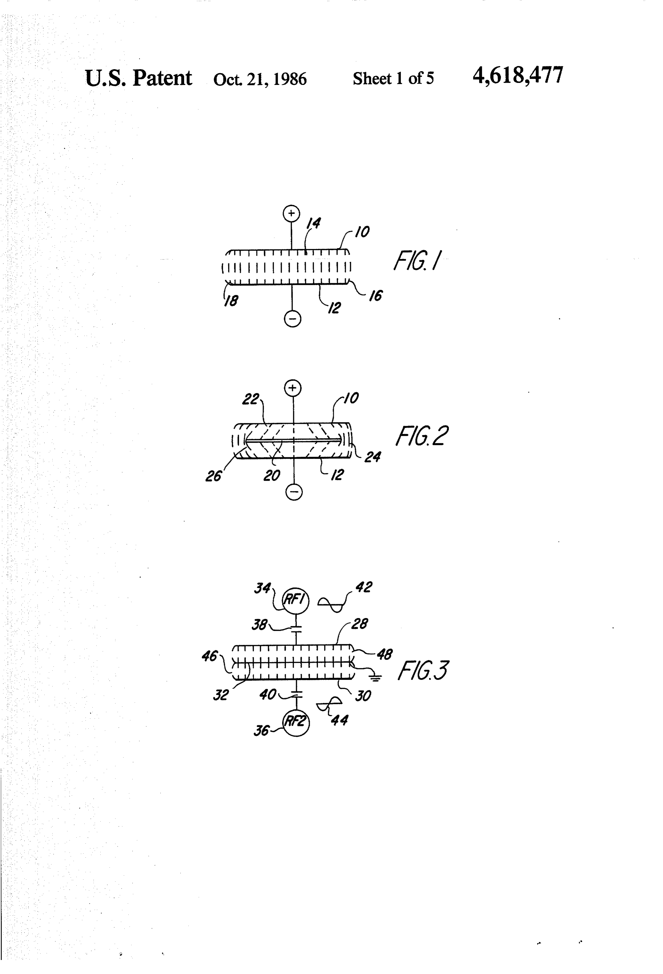
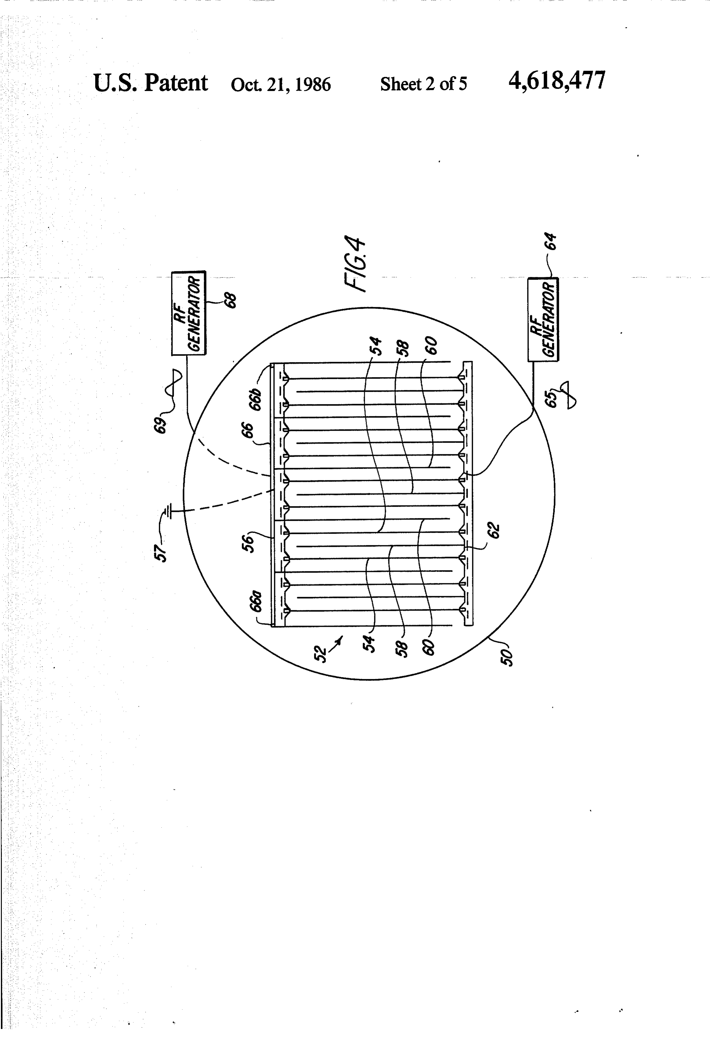
A complete understanding of the present invention nected to the upper r.f. power source 34 in series with may be obtained by reference to the accompanying 10 the upper electrode 28. The impedance matching net drawings, when taken in conjunction with the detailed work includes fixed and variable capacitors. A second description thereof and in which: impedance matching network 40 is connected to the FIG. 1 is a schematic representation of prior art appa second r. f. power source 36 in series with the lower ratus for producing a plasma field; electrode 30.
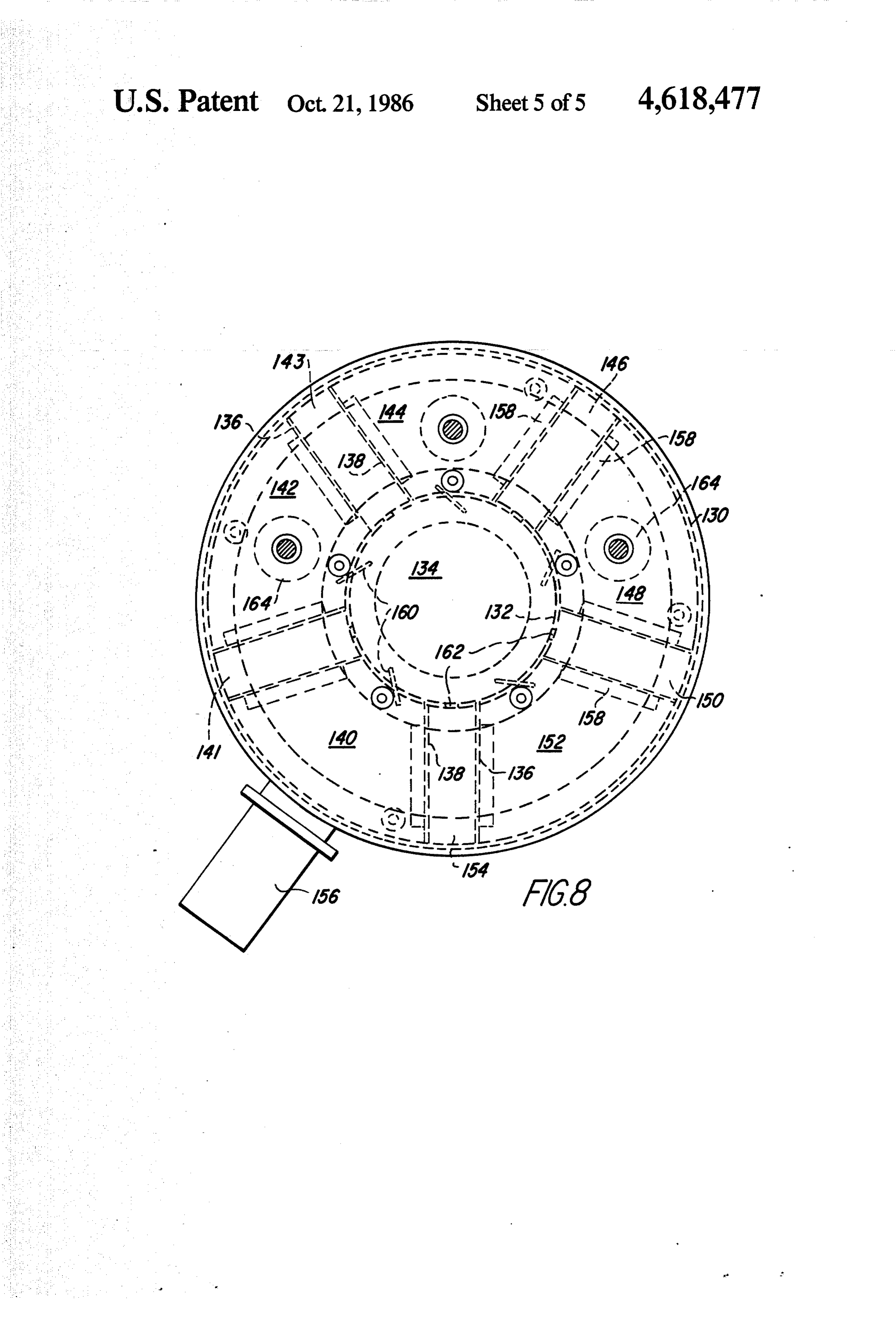
FIG. 2 is a schematic representation of prior art appa 15 Alternating current phase diagrams 42 and 44 indi ratus for creating a plasma field surrounding a substrate; cate the phase differential between r.f, power sources 34 FIG. 3 is a schematic representation of apparatus in and 36. It can be seen that the r.f, power sources 34 and accordance with the present invention for creating a 36 are 180 out of phase with one another at all times. It uniform plasma field; can also be seen that the electrical field generated be FIG. 4 is a sectional schematic representation of a 20 tween the upper and lower electrodes 28 and 30, respec reactor chamber; tively, is substantially uniform along the length of the FIG. 5 is a perspective view of a plurality of sub substrate 32, including the end portions 46 and 48 strates and hollow electrodes showing gas distribution thereof.
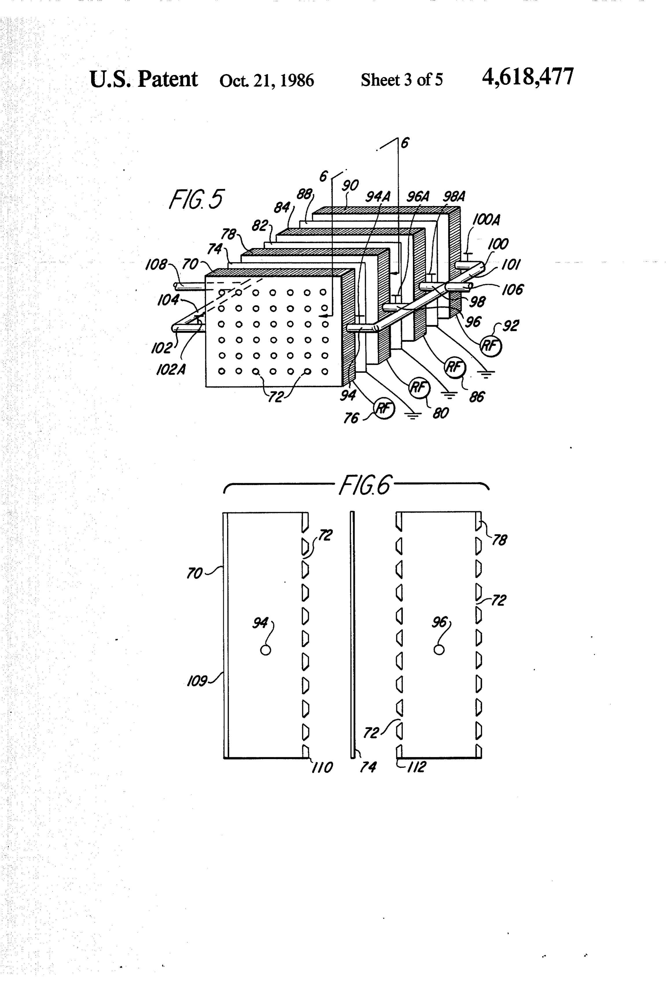
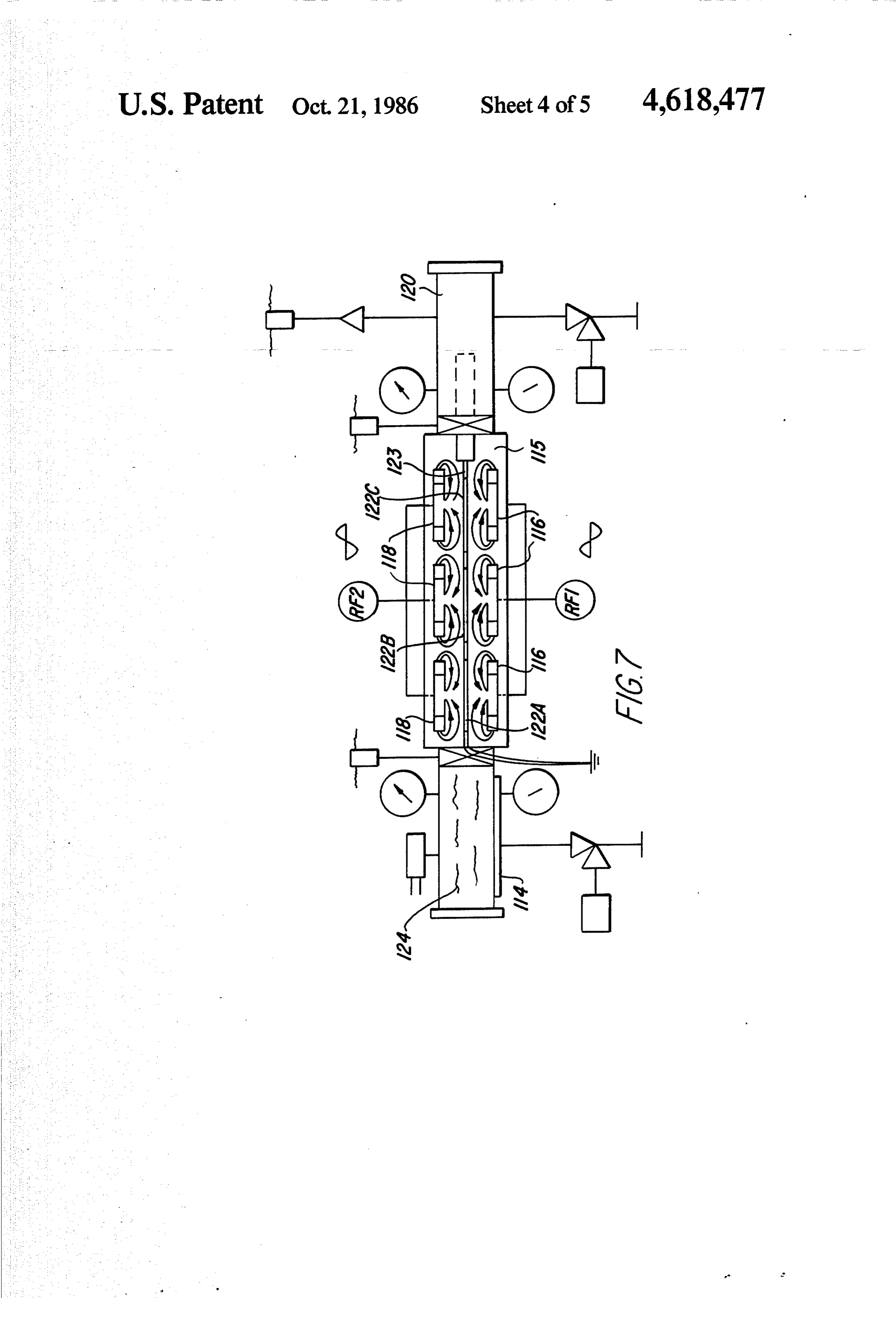
for use therewith; Referring now also to FIG. 4, there is shown a reac FIG. 6 is a cross-sectional view taken along line 6-6 25 tor chamber 50 suitable for maintaining a high vacuum of FIG. 5; for use in plasma processes. Such a chamber 50 can be FIG. 7 is a top sectional view of a continuous appara obtained from the Branson IPC Co., for example, as tus in accordance with the present invention; and Model No. 7415. The chamber 50 is evacuated and then FIG. 8 is an alternative embodiment of a continuous argon and oxygen or CF4 and oxygen are introduced apparatus for plasma processing. 30 thereto. A housing 52 is disposed within the reactor DETALEED DESCRIPTION OF THE chamber 50. In the housing 52 are mounted a plurality PREFERRED EMBODIMENT of cards or boards 54 suitable for having electrical cir cuits printed thereon. The boards 54 are electrically
Referring now to FIG. 1, there is shown a cross sec connected to one another by means of a bus structure 56 tional view of a conventional upper panel electrode 10 35 which, in turn, is grounded 57.
and a lower panel electrode 12, as is well known in the Electrodes 58 and 60 are placed alternately on either prior art. Both electrodes 10 and 12 have major axes side of the substrates 54. Electrodes 58 are electrically parallel to one another. This configuration is referred to connected to one another by means of a bus structure as parallel plate panel electrodes. 62. The bus structure 62 is electrically connected to an A power supply, not shown, is connected to each of 40 r.f, power generator 64 which is adapted, in the pre these electrodes 10 and 12. A positive charge is applied ferred embodiment, to operate at 13.5 MHz. It has been to the upper electrode 0 and a negative charge is ap discovered that for high aspect ratio through holes (i.e., plied to the lower electrode 12, as shown in FIG. 1 at a those whose ratio of hole length to diameter is greater given instant of time. The electrical field between paral than 6:1), an r.f. power generator operating at a much lel electrodes 10 and 12, identified by reference numeral 45 lower frequency (e.g., 50 KHz) prevents creation of 14, is substantially uniform in the center region. The polymer species from feed gas. U.S. Pat. No. 4,425,210 electrical field is more intense at both edges of the elec issued to Fazlin, for example, discloses relatively low trodes 10 and 12, however, as shown by reference nu frequency r.f. values. Thus the ionic plasma species merals 16 and 18, respectively. Accordingly, neither the etchants respond to the rif, field to reach the through electrical field 14 nor the resulting plasma, not shown, is 50 hole interior, providing uniform etch thereof. Phase uniform at all locations proximate the electrodes 10 and diagram 65 represents the phase of the r.f. generator 64 12. at a given moment of time.
Referring now also to FIG. 2, there is shown a cross Similarly, remaining electrodes 60 are connected to sectional view of the same parallel plate panel elec one another by means of another bus structure 66. Bus trodes 10 and 12 with a substrate 20 therebetween. The 55 structure 66 is electrically isolated from, although phys substrate 20 has a major axis substantially parallel to the ically supported by, bus structure 56 by means of insu major axis of the electrodes 10 and 12. The electrical lating members 66a and 66b. This second bus structure field at a given instant of time has relatively low inten 66 is electrically connected to a second r.f. power gen sity in the center region 22 proximate the electrodes 10 erator 68 also adapted to operate at 13.5 MHz. Phase and 12 and relatively high intensity at the outer edge 60 diagram 69 represents the phase of second r.f. generator regions 24 and 26 proximate the electrodes 10 and 12. It 68. The electrical signal from the first r.f. generator 64 can be seen that conventional parallel plate panel elec is 180° out of phase with the electrical signal generated trodes 10 and 12 with a substrate 20 intermediate them by the second rf generator 68 in the preferred embodi results in a nonuniform electrical field. ment. A comparison of AC phase diagrams 65 and 69 Referring now also to FIG.3, there is shown a plasma 65 indicates this phase differential relationship. reactor system having an upper electrode 28 and a It has also been discovered that a phase differential lower electrode 30 parallel thereto. Intermediate these between the rif. power generators 64 and 68 results in a two electrodes 28 and 30 and substantially parallel more uniform electric field than can be obtained either 9 by a single r.f. power generator or by a plurality of r.f. with hollow electrodes 78, 84 and 90 are not shown in generators, all being in phase with one another. The FIG. 5. All of the gas outlet pipes are connected to their phase differential need not be 180°. Thus, it should be associated hollow electrodes and to an outlet manifold understood that any phase differential between r.f. 104 for allowing gas to be exhausted from the hollow power generators 64 and 68 is within the scope of the electrodes uniformly.
present invention. It should also be understood that in A main gas feed line 106 is connected to the inlet another embodiment only one r.f. generator need be manifold 101. Similarly, a main gas exhaust line 108 is used in conjunction with the reactor chamber 50, pro connected to the outlet manifold 104. vided that two or more electrical output signals are It should be understood that the function of the gas independently created thereby, each being out of phase 10 inlet lines 106,94, 96, 98, 100 and manifold 101 and the with one another. function of the gas outlet lines 108, 102 and manifold Gas inlet and gas outlet pipes or tubes, not shown, are 104 can be reversed, if desired. That is, when appropri connected to the reactor chamber 50 to introduce gas ate, gas may be introduced by means of the main gas thereto or to remove gas therefrom as required. In oper exhaust line 108 and exhausted by means of the main gas ation, continuous gas introduction and exhaust can be 15 feed line 106. ---------- - accomplished by one or more of such lines connected to The use of inlet and outlet pipes in direct conjunction the chamber 50. with hollow electrodes maximizes gas distribution and Referring now also to FIG. 5, there is shown a hol flow across the substrates, thus ensuring uniformity of low electrode plasma system. This hollow electrode gas flow as well as uniformity of electric field. The plasma system is surrounded by a plasma chamber, not 20 advantage of these combined uniformities is a more shown, the interior of which is covered and protected accurate and uniform etching or deposition during the by nonconductive material such as Teflon material. plasma process.
(Teflon is a registered trademark of E. I. duPont de The function of valves 94a, 96a, 98a, 100a, 102a and Nemours Co.). those not shown should also be described for a clear A first hollow electrode 70 has a plurality of holes 72 25 understanding of the hollow electrode plasma system. drilled or punched in one major surface thereof. The When gas is introduced under pressure from the main holes are shown in phantom in FIG. 5. The holes 72 are gas feed line 106 through the inlet manifold 101, valves also shown in a rectilinear, uniform matrix pattern in the 94a,96a, 98a and 100a are placed in an open position to preferred embodiment. But it should be understood that allow the gas to reach and enter the hollow electrodes any pattern of holes 72 that ensures uniform gas distri 30 70, 78, 84 and 90 respectively. When the outlet pipe bution may be used. valves 102a and others, not shown, are placed in a In spaced apart relationship to this first hollow elec closed position, the gas is forced through the hollow trode 70 is a substrate 74, the major axis of which is electrode holes 72. In this manner, gas introduced into parallel to the major axis of the electrode 70. Connected the hollow electrodes 70, 78, 84, 90 under pressure by to the electrode 70 is an r.f, power supply 76. The sub 35 means of the corresponding gas inlet ports 94, 96, 98, strate 74 is grounded. 100 is distributed through the electrode holes 72 to Immediately adjacent and substantially parallel to the impinge on the substrates 74, 82, 88 in a substantially substrate 74 is a second hollow electrode 78 having a uniform manner.
plurality of holes, not shown, drilled or punched It can be seen that suitable settings of inlet valves 94a, through both major surfaces thereof. A second rif. 96a,98a and 100a and outlet valves 102a and others, not power supply 80 is electrically connected to this hollow shown, can result in gas flowing through the hollow electrode 78. In a like manner, another substrate 82 is electrodes 70, 78, 84, 90 in any one of a number of gas positioned substantially parallel to the hollow electrode flow patterns. Individual substrates or groups of sub 78 and is also grounded. strates can be processed by appropriately setting the A third hollow electrode 84 is positioned substan 45 inlet and outlet valves and selecting the main gas feed tially parallel to the substrate 82. This electrode 84 also line 106 and main gas exhaust line 108. It should also be has a plurality of holes, not shown, drilled or punched understood that any number of hollow electrodes and completely therethrough. Another r.f. power supply 86 alternating substrates may be used in accordance with is connected to this hollow electrode 84. Another sub this invention.
strate 88 is placed substantially parallel to the third 50 The gas inlet lines 94, 96, 98 and 100 are used to hollow electrode 84 and is also grounded. introduce gas with which a plasma reaction may be Finally, a fourth hollow electrode 90 having holes, maintained. Such gases are commonly CF4, O2, ammo not shown, drilled or punched therethrough on one nia, freon and the like. A gas composition having a major surface only is placed substantially parallel to the mixture of any of the aforementioned molecules can substrate 88 and is, in turn, electrically connected to a 55 also be used. Moreover, as previously mentioned, a last r.f. power supply 92. mixture of argon and oxygen can be used with relatively Gas inlet pipes 94, 96, 98 and 100 are connected to the low r.f, power generator frequencies to clean high as hollow electrodes 70, 78,84 and 90, respectively. Inde pect ratio through holes.
pendently operable valves 94a, 96a, 98a and 100a are In the preferred embodiment, the phase differential placed in corresponding inlet pipes 94, 96, 98 and 100 to 60 among rif. power sources is as follows. R.f. power shut off the flow of gas therethrough. Connected to the supplies 76 and 86 are in phase with one another. R.f. inlet pipes 94, 96, 98, 100 is an inlet manifold 101 for power supplies 80 and 92, while being in phase with one distributing gas evenly to the hollow electrodes 70,78, another, are 180 out of phase with the aforementioned 84, 90. r.f. power supply pair 76 and 86. Typical frequencies On the side of the electrodes opposite the gas inlet 65 are in the range of 50 KHz to 13.5 MHz. manifold 101 are gas outlet pipes, one of which being Referring now also to FIG. 6, there is shown a cross 102, having independently operable valves 102a corre sectional portion of hollow electrodes 70 and 78 and sponding to each pipe. The gas outlet pipes associated substrate 74 therebetween, taken along line 6-6 of
Page 10scan →
FIG. 5. The hollow electrode 70 has two walls: a left, description hereinabove presented in conjunction with solid wall 109 and a right wall 110 with holes 72. The FIG. 5. The flow of gas through the hollow electrodes holes 72 of the right wall 110 of electrode 70 are tapered116 and 118 and around and through the substrates in such a way as to allow a dispersion of gas from the 122a, 122b, 122c is shown in FIG. 7 as arrowed lines. left portion of the reactor chamber 50 (FIG. 4) to the 5 The hollow electrodes 116 and 118 have apertures on right portion thereof. Thus, the holes 72 in electrode 70 both sides as well as a series of holes forming a center have a smaller diameter on the left side of wall 110 and sink intermediate the walls facing the substrates 122a, a larger diameter on the right side of wall 110 of the 122b, 122c.
electrode 70. In an alternate embodiment, not shown, the reactor The orientation of the tapered holes 72 is reversed on 10 chamber 115 can be divided into two or more sections, the left wall 112 of the hollow electrode 78 so as to each being isolated from one another and each being allow uniform gas distribution to the rightmost major adapted to process substrates with a different gaseous surface of the substrate 74. It should be understood that composition. Alternatively, one or more secondary tapering of the holes 72 in the manner shown is useful reactor chambers can be placed between the primary for one substrate 74 shown in this example placed inter 15 reactor chamber 115 and the vacuum lock 120 in each of mediate two hollow electrodes 70 and 78. Alternative which a different plasma process can be maintained, arrangements and orientations of electrode holes 72 can each independently from one another. Such a series of easily be designed for modifications to the plasma pro plasma treatment stages can be useful, for example, in cess, depending on gas flow direction and number of etching, hole cleaning, board preparation and deposi substrates to be processed concurrently. 20 tion or any combination of the above. Referring now also to FIG. 7, there is shown a top Referring now also to FIG. 8, there is shown a circu view of a system adapted for use in a continuous plasma lar reactor chamber for continuous or semi-continuous treatment process having uniform gas flow and uniform plasma processing. The unit comprises essentially two electric field. A vacuum lock 114 is connected to a cylindrical elements 130 and 132 at the upper and lower linear reactor chamber 115. The vacuum lock 114 is 25 ends of which are secured upper and lower closure used to permit substrates 122a, 122b, 122c or other arti plate members, not shown in this top cross sectional cles to enter the reactor chamber 115 and move along a view.
transport track 123 without affecting the atmosphere or The inner cylinder 132, which forms the vacuum , vacuum therein. manifold 134, provides for connecting into a central Within the reactor chamber 115 and on one side of 30 vacuum pump.
the centerline thereof are three hollow electrodes 116 Between the outer and inner cylinders 130 and 132, which are electrically connected to an r.f, power sup numerous suitable radial partition assemblies such as ply, RFI. These three electrodes 116 are thus in electri 136 and 138, extending generally radially, divide the cal phase with one another. apparatus into a number of separate processing regions Three other hollow electrodes 118 are disposed on 35 or chambers, such as 140 through 154, inclusive. These the opposite side of the reactor centerline, each of separate chambers are constructed so that a ring-like which corresponding to one of the aforementioned platform, not shown, may be suitably rotated within and electrodes 116. The electrodes 118 are electrically con through them to carry substrates. nected to a second r.f. power supply RF2 and are in A conventional air lock or vacuum lock element 156 phase with one another, but 180° out of phase with leads into one of the chambers 140 and provides for respect to electrodes 116. loading and unloading the substrates carried on the A second vacuum lock 20 is attached to the reactor rotary ring platform. The control provides essentially a chamber 115 on the side opposite the first vacuum lock vacuum locking device which isolates the load and 114. Vacuum lock 120 is used to remove substrates unload chamber 140 from all other portions of the unit. 122a, 122b, 122c from the reactor chamber 115 without 45 Isolation of the vacuum processing chambers 140 affecting the atmosphere or vacuum therein. through 154 is achieved and effected by providing an In FIG. 7, substrates 122a, 122b, 122c are shown in a extremely close tolerance between the substrate carrier vertical orientation. It should be understood that the platform and a differentially pumped isolation compart orientation of the electrodes 116 and 118 may likewise ment 141.
be parallel to one another and horizontally disposed, 50 The carrier platform is arranged to pass from one similar to the schematic orientation shown in FIG. 3. chamber, such as 142 into an adjacent chamber 144, The substrates 122a, 122b, 122c are grounded in the through openings provided in the walls of the radially preferred embodiment, but may be maintained at a fixed extending partition assembly members 136 and 138. voltage potential throughout the plasma process. These openings are usually arranged in a rectangular In operation, the substrates 122a, 122b, 122c are ad 55 form through the use of a series of right angled duct-like vanced along the transport track 123 from the initial elements 158 to provide a controlled leakage path at vacuum lock 114 through the reactor chamber 115, both the top and the sides through which the platform between hollow electrodes 116 and 118 and through moves. One side of the angled elements 158 is fastened second vacuum lock 120. A drive mechanism, not to the partition wall 136, while the other side is free, shown, advances each substrate on the transport track 60 except for the connection at the abutting edges which 123 linearly from one location in the reactor apparatus are welded or soldered to make a tight fit. This con to another sequentially and continuously. Heating ele trolled leakage path provides efficient isolation of one ments 124, disposed within the initial vacuum lock 114, process environment from another. can be used to preheat the substrates 122a, 122b, 122c The ring platform may be driven from any desired before plasma etching or deposition occurs. 65 form of prime mover such as a motor and appropriate Provision is made, not shown, for introducing and gears, not shown. The outer edge of the ring-like plat exhausting gas used in plasma treatment through the form may be formed as a toothed member, for example, hollow electrodes 116 and 118 in accordance with the with the teeth adapted to mesh with the teeth of a driv 11 ing pinion so that rotation is readily achieved. Of cessing chambers makes necessary only a single pump course, other forms of drives such as frictional members out unit.
may be utilized. The apparatus described here is purely With the circular reactor arrangement, the loading of for convenience. substrates as well as the unloading thereof is achievable As can be appreciated from the showing of FIG. 8, by any desired form of simple automatic method and the central vacuum manifold 134 is common to all of the permits a continuous or semi-continuous operation formed chambers, 140 through 154. without causing the environment to vary. It is also A valve element 160 of the generally butterfly type readily controllable by computer control for different leads from each formed processing chamber into this types of processing and purely automatic operation. central manifold 134. By suitable rotation of the valve O It should be understood that the circular reactor 160, the specified processing chamber can be opened to apparatus, as well as the longitudinal reactor apparatus the manifold 134 or can be closed off therefrom. In this described in FIG. 7, can be used with boards or sub way, a single high speed vacuum pumping system, such strates transported either vertically or horizontally. as a diffusion or turbo pump, when connected to lead to An oxygen plasma can be used in the continuous vacuum manifold 134, can provide the necessary vac 15 plasma device hereinabove described to improve adhe uum to all of the different formed processing chambers sion between copper, the most commonly used elec and radial partition assemblies. The pumping system trical,conductor, and epoxy, a nonconductive material. can be further connected to various mechanical pumps Since other modification and changes varied to fit for establishing desired vacuum level. particular operating requirements and environments Each of the separate valves 160 constitutes a control 20 will be apparent to those skilled in the art, the invention lably variable conductance element which is supported is not considered limited to the examples chosen for in the inner cylindrical wall. It is thus possible to have purposes of disclosure, and covers all changes and mod a multiplicity of differentially pumped processing ifications which do not constitute departures from the chambers because of the radial partition assemblies true spirit and scope of this invention. separating each from the central vacuum manifold 134. 25 What is claimed is:
The vacuum manifold communication to the radial 1. An apparatus for generating a substantially uniform partition assemblies between the separate chambers, plasma for processing a substrate having two major such as 144 and 148, is provided by a fixed or controlla surfaces, each of said major surfaces having electrically ble conductance entrance port 162 connected to corre conductive portions disposed thereon, comprising: sponding isolation compartments between walls such as 30 (a) two electrode means oppositely disposed with 136 and 138, so that the pressure therein is almost as low respect to one another on either side of said sub as that within the manifold 134 leading to the vacuum strate;
pump. Because of leakages and similar effects, this iso (b) a first radio frequency power source operatively lating region or compartment is usually at a slightly connected to the first of said electrode means; and higher pressure than that of the vacuum manifold 134. 35 (c) a second radio frequency power source opera The highest system pressure is, of course, found within tively connected to the second of said electrode such chambers as 140, 142, 144, 148, etc. It is these means, said second radio frequency power source regions or compartments which constitute the various being out of phase with respect to said first radio processing component volumes. frequency power source.
The ring platform successively moves within the 2. The apparatus in accordance with claim 1 wherein different processing chambers and, as this occurs, the said first and second radio frequency power sources are supported substrates which may be included within an 180 degrees out of phase with respect to one another. appropriate atmosphere introduced in any appropriate 3. The apparatus in accordance with claim 1 wherein and desired manner may be sputter treated by r.f. excita said substrateis maintained at a fixed voltage potential. tion of sputtering cathode elements 164 positioned 45 4. The apparatus in accordance with claim 3 wherein within the various chambers or other vacuum pro said fixed voltage potential is zero volts. cesses. If desired, and in order that the relative pressures 5. The apparatus in acordance with claim 3 wherein in the different chambers shall be separably controlla said fixed voltage potential is less than zero volts. ble, it is apparent that each of the control mechanisms 6. The apparatus in acordance with claim 1 wherein conventionally represented for turning the valves 160 50 said electrically conducive portions of said substrate are may be automatically operated. The directly pumped electrical lines.
controlled leakage slots in the radial partition assembly 7. The apparatus in accordance with claim 2 wherein 136, 138 eliminate process chamber contamination from said substrate is maintained at a fixed voltage potential. one compartment to that adjacent to it. 8. The apparatus accordance with claim 7 wherein, In operation, the substrate carrier platform is con 55 during said plasma processing, material is deposited fined to the vacuum environment. This reduces out onto said substrate.
gassing. The directly pumped radial partition assem 9. The apparatus in accodance with claim 7 wherein, blies, as already noted, serve substantially to eliminate during said plasma processing, material is etched from compartment contamination. said substrate.
A 4 ft. diameter circular processing chamber is ap 60 10. The apparatus in accordance with claim 7 proximately the equivalent of an 11 ft. length linear, wherein, during said plasma processing, material on said in-line section. The circular processing system provides substrate is oxidized.
for substrate loading and unloading in adjacent areas, as 11. The apparatus in accordance with claim 7 contrasted with the in-line system which requires load wherein, during said plasma processing, material dis ing and unloading at opposite ends of the system, as 65 posed on said substrate is reduced. previously described. 12. The apparatus in accordance with claim 7 In addition, the circular arrangement (FIG. 8) with wherein said plasma is used to clean material disposed the centrally located pumping system beneath the pro on said substrate.
Page 12scan →
13. The apparatus in acordance with claim 7 wherein (b) a first electrode means and a second electrode said substrate is a printed circuit board. means in electrically operative relationship with 14. The apparatus in accordance with claim 7 said substrate; and wherein said substrate is a printed circuit card. (c) a first source of radio frequency power opera 15. The apparatus in acordance with claim 7 wherein tively connected to said first electrode means and a said substrate is a component of a printed circuit board. second source of radio frequency power opera 16. The apparatus in accordance with claim 7 tively connected to said second electrode means, wherein said electode means are substantially parallel to said first and second sources of radio frequency one another. power having a phase differential with respect to 10 one another.
17. An apparatus for generating a substantially uni form plasma for processing a printed circuit board hav whereinThe25. apparatus in accordance with claim 24 said phase differential is 180 degrees.
ing thru holes therein, comprising: 26. The apparatus in accordance with claim 24 (a) two electrode means oppositely disposed with wherein said predetermined voltage potential of said respect to one another on either side of said printed 15 electrically conductive portions of said substrate is zero circuit board; volts.
(b) a first radio frequency power generator opera 27. The apparatus in accordance with claim 24 tively connected to the first of said electrode wherein said predetermined voltage potential of said means; and f electrically conductive portions of said substrate is less (c) a second radio frequency power generator opera 20 than zero volts.
tively connected to said second electrode means, 28. The system in accordance with claim 25 wherein said second radio frequency power generator being said electrically conductive portions of said substrate out of phase with respect to said first radio fre are electrical lines.
quency power generator. 29. The apparatus in accordance with claim 25 wherein said electrode means are substantially parallel 18. The apparatus in accordance with claim 17 25 to one another.
wherein said first and second radio frequency power 30. Apparatus for processing a printed circuit board generators are 180 degrees out of phase with respect to having a plurality of thru holes therein in a plasma field, one another. comprising:
19. The apparatus in accordance with claim 18 30 (a) means for maintaining said printed circuit board at wherein said printed circuit board is maintained at a zero voltage potential invariant over the time of fixed voltage potential. processing;
20. The apparatus in accordance with claim 19 (b) a first electrode means in operative relationship wherein said fixed voltage potential is zero volts. with a first portion of said printed circuit board; 21. The apparaus in accordance with claim 19 35 (c) a second electrode means in operative relationship wherein, during said plasma processing, material resid with a second portion of said substrate, said second ing in said thru holes is etched. electrode means being substantially parallel to said 22. The apparatus in accordance with claim 19 first electrode means; . wherein, during said plasma processing, material resid (d) a first means for creating radio frequency power ing in said thru holes and proximate thereto is cleaned. operatively connected to said first electrode means; 23. The apparatus in accordance with claim 9 and wherein said electrode means are substantially parallel (e) a second means for creating radio frequency to one another. power operatively connected to said second elec 24. Apparatus for processing a substrate having elec 45 trode means, the respective frequencies created by trically conductive portions thereon in a plasma field, said first and second means for creating radio fre comprising: quency power having a phase differential of 180 (a) means for maintaining said electrically conductive degrees with respect to one another. 31. The apparatus in accordance with claim 24 portions at a predetermined voltage potential, said wherein said substrate comprises a portion of a semicon potential being invariant over the time of process 50 ductor device.
1ng; k k 3k sk k
Provenance
- Collection
- Patents citing this work
- Pages
- 12
- Method
- pdftotext (the PDF's own text layer) + pdftoppm 300dpi page scans
- Patent office record
- patents.google.com →
- Source
- Google Patents citing-documents table
- Assignee
- International Business Machines Corporation
- Published
- 1986-10-21
- Transcribed from
- patentimages.storage.googleapis.com →