

patent · US4274395A
Solar energy absorber
23 June 1981
Text
Page 1scan →
United States Patent (19)
Bangs
54 solar energy absorber
(76 Inventor: John R. Bangs, 12 Randall Rd.,
Princeton, N.J. 08540
51 Int. C. ........................ e o sa a see so was as to as F24J 3/02 52 U.S. Cl. ..................................... 126/432; 126/450
3,974,822 8/1976 Patil ..... 26/90 X
3,996,918 12/1976 Quick .................................. 126/432
4,078,548 3/1978 Kapany . 126/441X 4,130,108 12/1978 Patil ..................................... 26/901 4,136,669 1/1979 Lane .................................... 126/450 4, 75,542 11/979 Duchene .............................. 126/449 4,201,196 5/1980 Zani ................................. 26/449 X Primary Examiner-Samuel Scott
Assistant Examiner-Randall L. Green
Attorney, Agent, or Firm-Gary M. Nath
A solar heat collector is disclosed having a cover plate mounted in spaced relation with a solar energy absorber and having interposed between said cover plate and solar absorber an infrared absorber material.
7 Claims, 3 Drawing Figures
Azzzzzzyz
Drawings
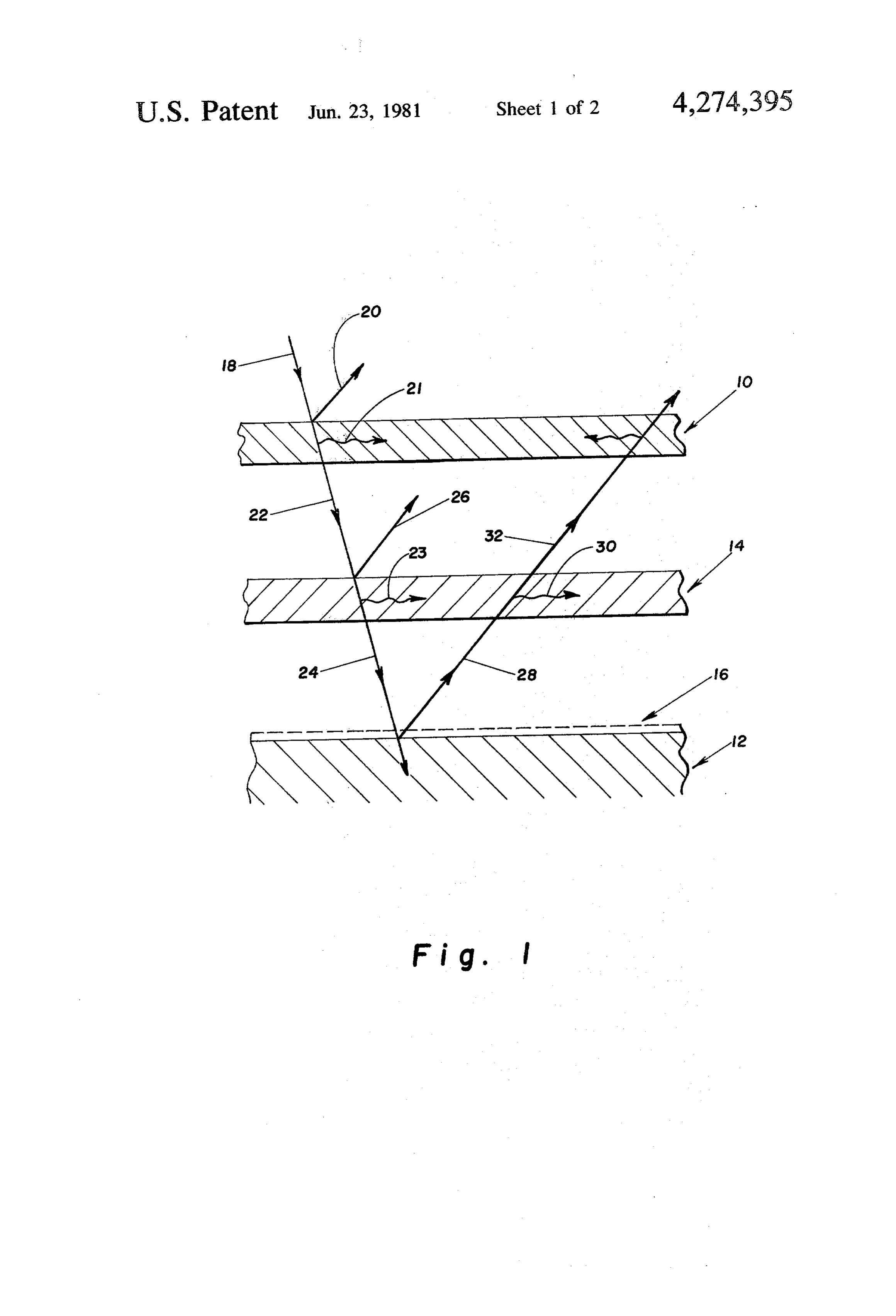
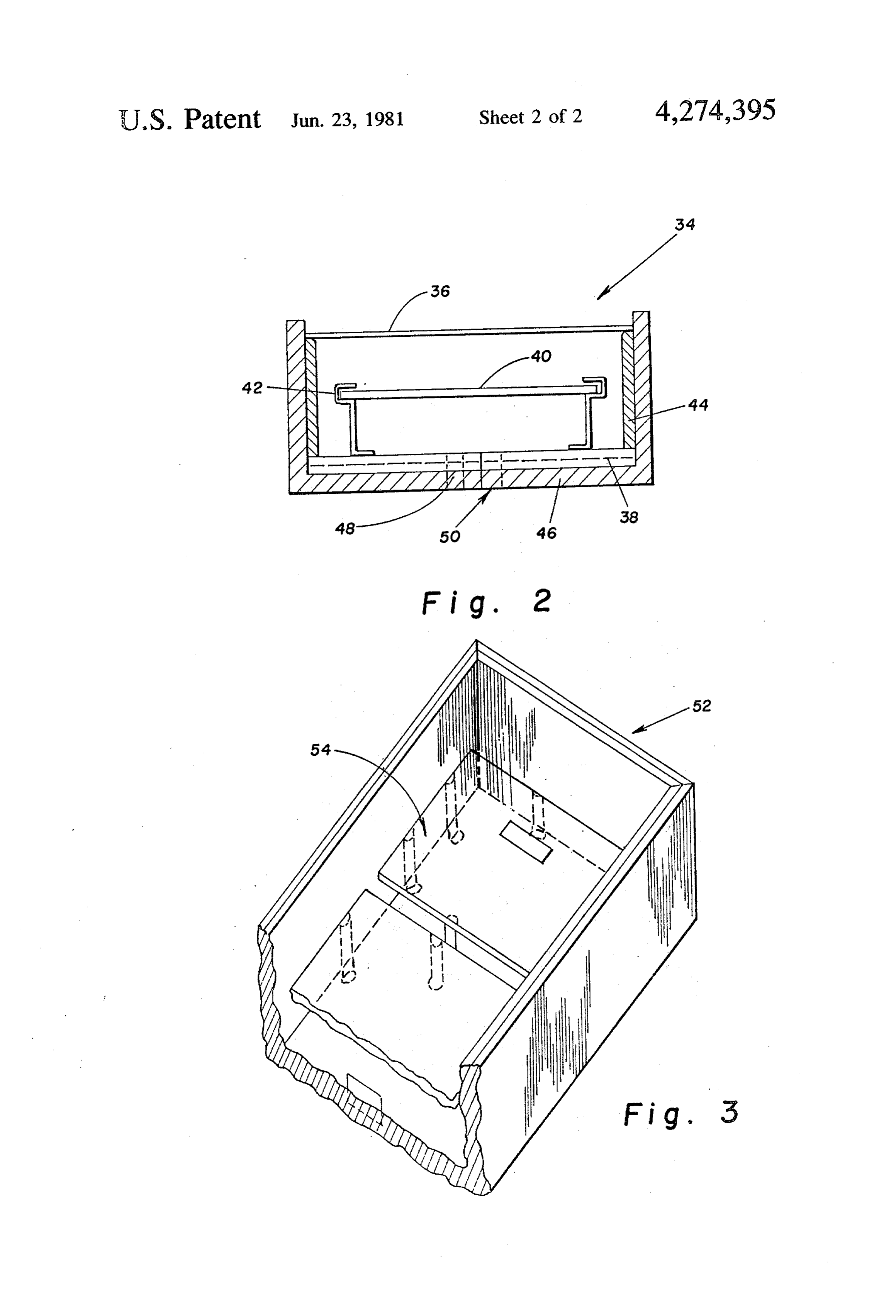
FIG. 1 is an illustrative view of the radiation energy
Page 2drawing sheetscan →
Page 3drawing sheetscan →
Page 4scan →
Brief description of the drawings
Solar energy absorber
FIG. 1 is an illustrative view of the radiation energy
FIELD OF THE INVENTION balance of a solar heat conductor in accordance with the teachings of the invention;
This invention relates to solar energy absorbers and FIG. 2 is a side elevation, in section, showing a solar in particular to a solar heat collector. More especially, heat collector embodying the invention; and this invention relates to a low cost solar heat collector FIG. 3 is an isometric view of a solar heat collector in for heating homes, farm buildings, greenhouses, swim accordance with the teachings of the invention, having ming pool enclosures, and the like, or for supplementing 10 portions removed for purposes of clarity. heat from conventional fuel sources which is provided with means for reducing heat loss and maximizing heat DETALED DESCRIPTION OF THE transfer from the heat absorbing materials to the heat INVENTION transfer media. With reference to FIG. 1, this invention, in general, 15 relates to a solar heat collector including a cover plate
Description of the prior art
10 mounted in spaced relation to a solar heat absorber
Conventional flat-plate collectors generally consist of 12 having interior disposed therebetween an infrared a black radiation-absorbing surface backed by insulation absorbing member 14.
and covered by one or more layers of transparent cov Cover plate 10 can be comprised of any suitable mate ers. See for example Yu U.S. Pat. No. 3,943,911, Gillery 20 rial which will readily allow solar rays to be transmitted U.S. Pat. No. 3,981,293 and Rosenberg U.S. Pat. No. rather than reflected. It may comprise a transparent 4,056,094. plastic material, preferably an acrylic material resistant Solar radiation is transmitted through the transparent to ultraviolet rays, or other material such as ultraviolet cover and absorbed by the black surface. The absorbed resistant mylar, or glass. If desired, multiple transparent solar heat can be removed by air, water, or other suit 25 members can be employed in generally laminar con able heat transfer fluid passed in heat exchanging rela struction with a void space between each member. For tionship with the heated surface. As described in a pub purposes of achieving greatest efficiency within a rea lication entitled "Solar Energy Utilization for Heating sonable economic limit, however, it is preferred that and Cooling' compiled by John Yellot, Arizona State 30 one member be provided, that is merely an exterior University and referenced as NSF 74-41, the prior art exposed The cover plate.
infrared absorbing material may be selected from approaches to solar heat collectors have been numer ous, with each possessing deficiencies affecting the aarewide range of commercially available materials which overall operation and efficiency of the solar heat collec totalcapable of transmitting at least 40 percent of the tor. In some of the prior art designs, the heat transfer 35 least 45 percentand solar ray preferably 45 to 65 percent, and at the total visible light ray and prefera media flows in tubes or along troughs, which devices bly 50 to 70 percent entering the collector. Use of an result in heat loss by convection, reflection or evapora infrared absorbing material having such properties per tion into the environment. If the tube design, the entire mits the efficient transmittance of visible energy rays to absorber surface is exposed and thus radiates heat up the absorber; maximizes infrared absorportion; and con wards and outwards. In the trough design, those por 40 comitantly minimizes radiant energy loss. As such, tions of the absorber which are exposed will radiate infrared absorber serves to pass the solar radiationthe to heat upwards and cause evaporation. absorber 12 while absorbing significant amounts of in One effort to reduce heat loss and accordingly im prove operation efficiency is described by Gillery in frared energy which was previously trapped between the cover plate and absorber in prior art devices.
U.S. Pat. No. 3,981,293. This patent discloses use of a 45 The absorber 12 has a surface 16 that has a high ab solar energy absorber and a cover plate, wherein the sorptive potential. If desired, absorber 12 may be dark latter has a preselected transmittance coefficient for ened so as to absorb solar energy radiation up to 1.5 solar radiation in the wavelength range of 0.3 to 2.1 microns in wavelength and transmit heat, primarily as microns and a reflectance coefficient for infrared radia reradiated infrared rays, to the air flowing above. The tion in the wavelength range of about 2 to 15 microns. 50 absorber may optionally contain a heat insulative base, Although heat loss is reduced by using such coatings, formed from conventional insulating materials, such as similar approaches are not completely satisfactory be asbestos board, fiber board, cellular glass, foamed and cause of the increased weight and/or cost which makes cellular polymeric material such as freon blown ure the already expensive collector even more expensive to thane foam, polystyrene, polyurethane and the like. purchase and difficult to construct. 55 When used, a sheet or layer of surface 16 material over SUMMARY OF THE INVENTION lies the insulative base. The surface 16 may be rigid or flexible preferably in the form of a blackened plate or
This invention relates to an improved heat collector film such as a painted metal sheet or dyed or pigmented of the type having at least one cover plate for transmit polymer rigid or semi-rigid sheet or film. ting solar radiation mounted in spaced relation to means 60 The solar heat collector is characterized by the en for absorbing solar radiation and having interior dis ergy balance diagraned in FIG. 1 which approximates posed between both means, at least one infrared absorb using a solar energy ray 18 having a total solar radiation ing member having peripheral dimensions smaller than of 100% (49% visible and UV-below 0.7 microns said cover plate and absorber means. The improvement wavelength and 51% IR-above 0.7 microns wave includes facilities for permitting turbulant flow of a heat 65 length.) When solar energy ray 18 impinges on the transfer fluid through solar collector in close proximity outer surface of cover plate 10, a portion of the energy to said absorber and infrared absorbing member to max of ray 18 is lost due to reflectance ray 20 (5% with 5 imize heat transfer and efficiency. mm. thick glass) and absorption ray 21 (3% with 5 mm.
Page 5scan →
thick glass). The remaining energy, 92% of ray 18 necessary to achieve effective heat transfer by ensuring passes through the cover plate 10 as transmitted solar turbulent flow of the heat transfer fluid. The random energy ray 22 which then impinges on infrared absorber eddies, i.e. swirling motion of the fluid, which occur in material 14. turbulent flow, serve to minimize the thickness of the The infrared absorber material 14 absorbs a signifi- 5 still air layer next to any solid surface by a scouring cant amount of infrared rays (about 34%) as well as action. The thermal conductivity through the still air some solar radiation (about 10%) as ray 23 while trans layer is thus increased and thus transfer of energy to the mitting ray 24 to absorber 12. A portion of ray 22 is heat transfer fluid is enhanced.
reflected toward the inner surface of cover plate 10 and FIG. 3 shows in isometric view a solar heat collector is shown as internal ray 26. 10 in accordance with the teachings of the invention. The As absorber 12 absorbs the solar energy from ray 24 solar heat collector is similar in construction to the solar (35% solar radiation and 13% infrared radiation), it heat collector of FIG. 2 except that FIG. 3 depicts begins to heat up and emit infrared energy ray 28 back toward infrared absorber 14 which absorbs a portion of multiple infrared absorbing materials 54. The use of ray 28 as absorbed energy ray 30. About 43% of the 15 and inducement of materials multiple absorbing aids in air flow circulation turbulent flow.
infrared energy is re-radiated from absorber 12, of which a substantial portion was heretofore lost. By thatTheminor invention being thus described, it will be obvious variations may be made without departing employing infrared absorber 14, approximately 31% of from the spirit and scope of the invention. Such varia the total entering solar ray is reabsorbed as infrared tions are intended radiation. The remaining portion of infrared energy 20 tion as set forth in tothebeclaims. within the scope of the inven (about 12%) is lost to the solar heat collector due to What is claimed is:
absorption and transmittance through cover plate 10 as 1. A solar heat collector, comprising: ray 32. This results in a net energy efficiency of approxi (a) at least one cover plate capable of passing solar mately 78% whereas in the absence of an infrared ab energy having a major surface with predetermined sorber material maximum efficiency is merely about 25 peripheral dimensions and shape;
FIGS. 2 and 3 show various views of a solar heat (b) a solar energy absorber having peripheral dimen collector embodying teachings of this invention. As can sions and shape similar to said cover plate; be appreciated, the solar heat collectors are presented (c) at least one infrared absorbing member interiorly for illustration purposes only. 30 supported, disposed and spaced between said cover Shown in FIG. 2 is a solar heat collector 34 including plate and solar energy absorber and having periph cover plate 36 mounted at the parameters in spaced eral dimensions smaller than said cover plate and relation to absorber 38, each having the same peripheral said solar energy absorber; dimensions and shape. Interposed between them is in (d) means for mounting said cover plate and solar frared absorber material 40 having peripheral dimen- 35 energy absorber in spaced relation with said infra sions smaller than said cover plate and said absorber. red absorbing member;
- Cover plate 36 and absorber 38 are fastened at their (e) inlet means defining an area through which a heat perimeters by suitable cement of other fastening means transfer fluid may pass into said collector under, which are selected to be leak proof, chemically resis above, and around the infrared absorbing member tant, non-volatile and able to withstand expansion and 40 to permit turbulent flow of the heat transfer fluid contraction. Infrared absorber material 40 is preferably through the collector in close proximity to said fastened approximately equaldistance from cover plate absorber and infrared absorbing member; and 36 and absorber 38 with any means suitable for main (f) outlet means defining an area through which the taining the infrared absorber in place without sealing its heat transfer fluid passes out of said collector. perimeter. Suitable means include clamp-type means 45 2. The solar heat collector of claim 1 wherein said such as 'clamps 42, flexible clamps with rivets, screw mounting means is a rigid spacer frame having periph grommet means or mechanical designs that maintain eral dimensions and shape similar to said cover plate, their bonding and locking characteristics in tension, and and solar energy absorber, said frame mounting mar compression. ginal edge portions of the major surfaces of said cover The distance between the cover plate, infrared ab- 50 plate and said solar energy absorber to provide a com sorber and absorber is not critical to practice the inven partment therebetween.
tion. To reduce heat loss by conduction, it is preferred 3. The solar heat collector of claim 2 wherein said to have a distance of inch to 4 inches between each infrared absorbing member is mounted by supporting material. means between said cover plate and said solar energy To reduce heat losses due to conduction, the cover 55 absorber.
plate and absorber may be mounted in a heat insulating 4. The solar heat collector of claim 3 which includes box, such as to provide insulation on sidewalls 44 and clamping means for supporting said infrared absorbing bottom 46. member between said cover plate and said absorber. The heat transfer fluid, which is preferably in gaseous 5. The solar heat collector of claim 1 wherein said form and most preferably air, is caused to flow in one 60 cover plate is glass.
direction in turbulent form from inlet trough 48 to out 6. The solar heat collector of claim 1 wherein said let trough 50. The flow must be fast enough to permit heat transfer fluid is air.
turbulent flow of the heat transfer fluid through the 7. The solar heat collector of claim 1 wherein said collector in close proximity to the absorber and infrared cover plate is a transparent plastic material. absorber material. Air speed is critical only to the extent 65 ak sk x :k 2k
Provenance
- Collection
- Patents citing this work
- Pages
- 5
- Method
- pdftotext (the PDF's own text layer) + pdftoppm 300dpi page scans
- Patent office record
- patents.google.com →
- Source
- Google Patents citing-documents table
- Assignee
- Bangs John R
- Published
- 1981-06-23
- Transcribed from
- patentimages.storage.googleapis.com →