

patent · US4286578A
Solar energy absorbing panel
1 September 1981
Text
Page 1bibliographic recordscan →
United States Patent (19)
McArthur
(54). SOLAR ENERGY ABSORBING PANEL
76 Inventor: William H. McArthur, P.O. Box 236,
Forest City, N.C. 28043
Related U.S. Application Data 62 Division of Ser. No. 827,948, Aug. 26, 1977, Pat. No.
51 Int. Cl. ................................................. F24J 3/02 52 U.S. Cl. .................................... 126/429; 126/447;
3,089,670 5/1963 Johnson ....... . 126/449 3,863,621 2/1975 Schoenfelder ... 126/429 4,016,861 4/1977 Taylor .......... ... 126/446 4,019,494 4/1977 Safdari ................................. 126/449 4,019,496 4/1977 Cummings ........................... 126/449 4,074,706 2/1978 Hadju et al. ......................... 126/447
4,083,360 4/1978 Couruoisier et al. ................ 26/450 4,088, 117 5/1978 Keyes ................................... 126/449 4.088,266 5/1978 Keyes ................................... 26/449 4,120,283 10/1978 Eder . - - - -a a - - - - - -- -- - - - 126/449
4,126,014 11/1978 Kay ...................................... 126/449 4,150,661 4/1979 Callegari et al. .................... 26/445 4,178,912 12/1979 Felter ................................... 126/449 4,186,722 2/1980 Muessig ............................... 126A450 Primary Examiner-Daniel J. O'Connor
Attorney, Agent, or Firm-Bell, Seltzer, Park & Gibson
A solar energy absorbing panel is provided which may be integrally incorporated into a conventional building structure so that it does not protrude from the normal contour of the building, and which utilizes components of the building structure as a part of the collecting appa ratus to thereby minimize the cost thereof. The panel is composed of a plurality of interconnected side-by-side, generally U-shaped sections, with the adjacent sides of adjacent sections forming parallel fins which facilitate transfer of heat to air passed therealong. Also, slot means are provided at one end edge of the panel which is adapted to receive the other end edge of another like panel therein, whereby the panels may be joined in an end-to-end arrangement.
7 Claims, 12 Drawing Figures
Drawings
Page 2drawing sheetscan →
Page 3drawing sheetscan →
Page 4drawing sheetscan →
Page 5drawing sheetscan →
Page 6scan →
of each panel for receiving the other end edge of an
SOLAR ENERGY ABSORBING PANEL other like panel therein, whereby a number of the panels may be readily joined in an end-to-end arrangement.
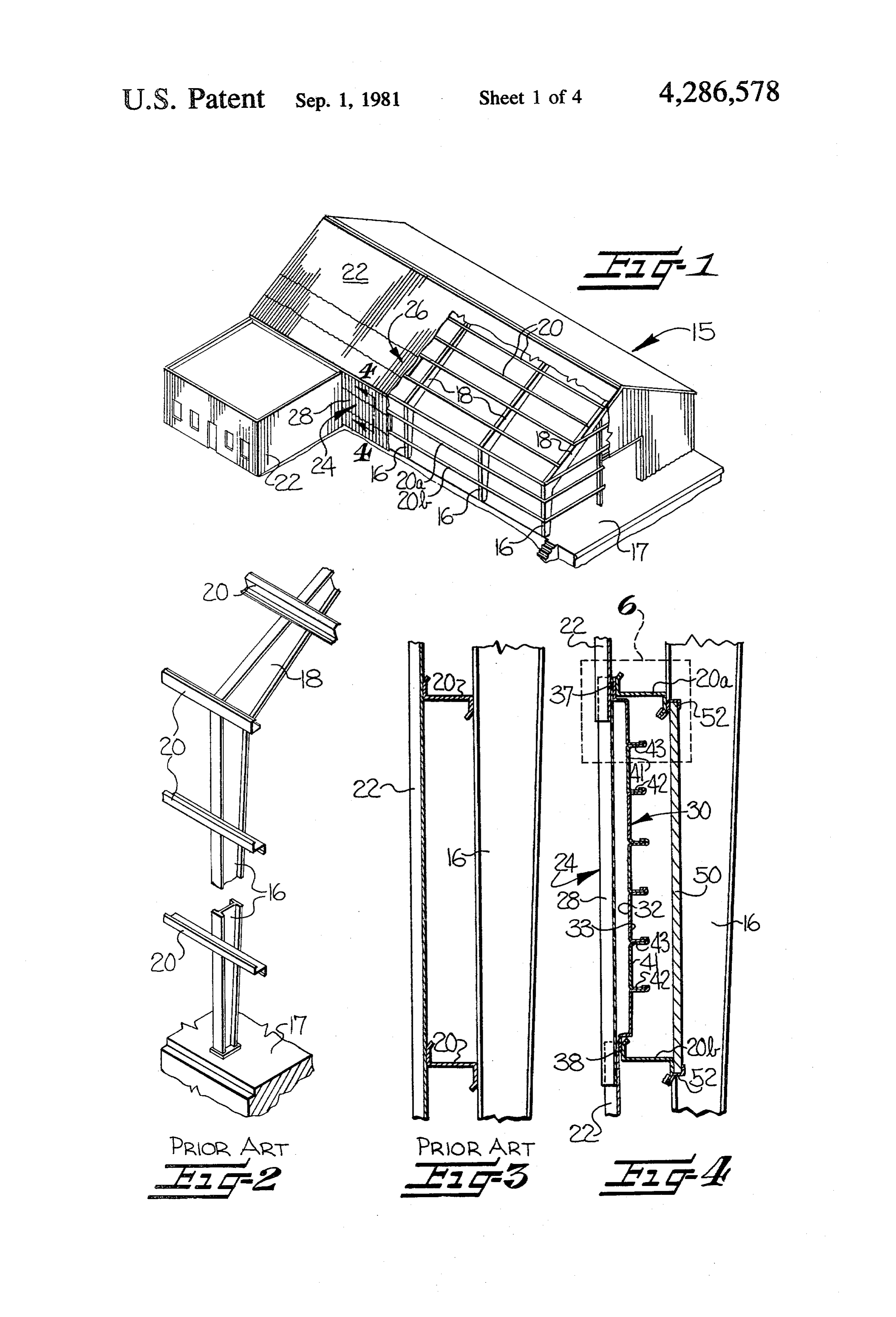
This is a division of Application Ser. No. 827,948, The panel of the present invention is typically utilized filed Aug. 26, 1977, now U.S. Pat. No. 4,184,476. 5 in a solar collector which is integrally incorporated in a The present invention relates to a solar energy ab building wall structure, and which comprises a plurality sorptive panel for use in a solar energy collector. of parallel, spaced apart structural support members, In recent years, solar heating systems for collecting, transparent exterior panel means mounted to the outside storing and distributing the sun's heat energy to the edges of two adjacent support members, and with the interior of a building have been the subject of consider O solar energy absorptive panel mounted between the two able developmental activity. Typically, known systems adjacent support members and underlying the transpar include solar collectors in the form of large rectangular ent panel means. Means are provided for conveying a frames which are placed directly on a roof or wall of fluid along the solar energy absorptive panel whereby the building, and which comprise a sheet metal solar the solar energy is collected by the absorptive panel and energy absorber, a covering sheet of glass or plastic 15 transferred to the fluid. Additional exterior panel means which is transparent to solar radiation, and an insulating are mounted to the outside edges of the remaining Sup material behind the absorber. In an air type collector, port members, such that the transparent panel means air is adapted to be passed along the absorber so as to and additional panel means are substantially co-planar absorb heat therefron, and the heated air is then ducted and collectively define the exterior surface of the wall directly into the interior of the building or to a heat 20 structure. Further, interior panel means are mounted to storage unit. In a liquid type collector, water or similar the inside edges of the two structural support members, liquid is passed through channels attached to the ab such that the solar energy absorbing panel, two support sorber, and then is piped to a heat transfer unit or stor members, and interior panel means collectively define age unit. m an air passageway through which air is circulated, with The above described conventional solar collectors 25 the finned surface of the solar energy absorbing panel possess several disadvantages which have hindered extending into the passageway to facilitate heat transfer wide-spread acceptance and use. Among these disad to the circulating air.
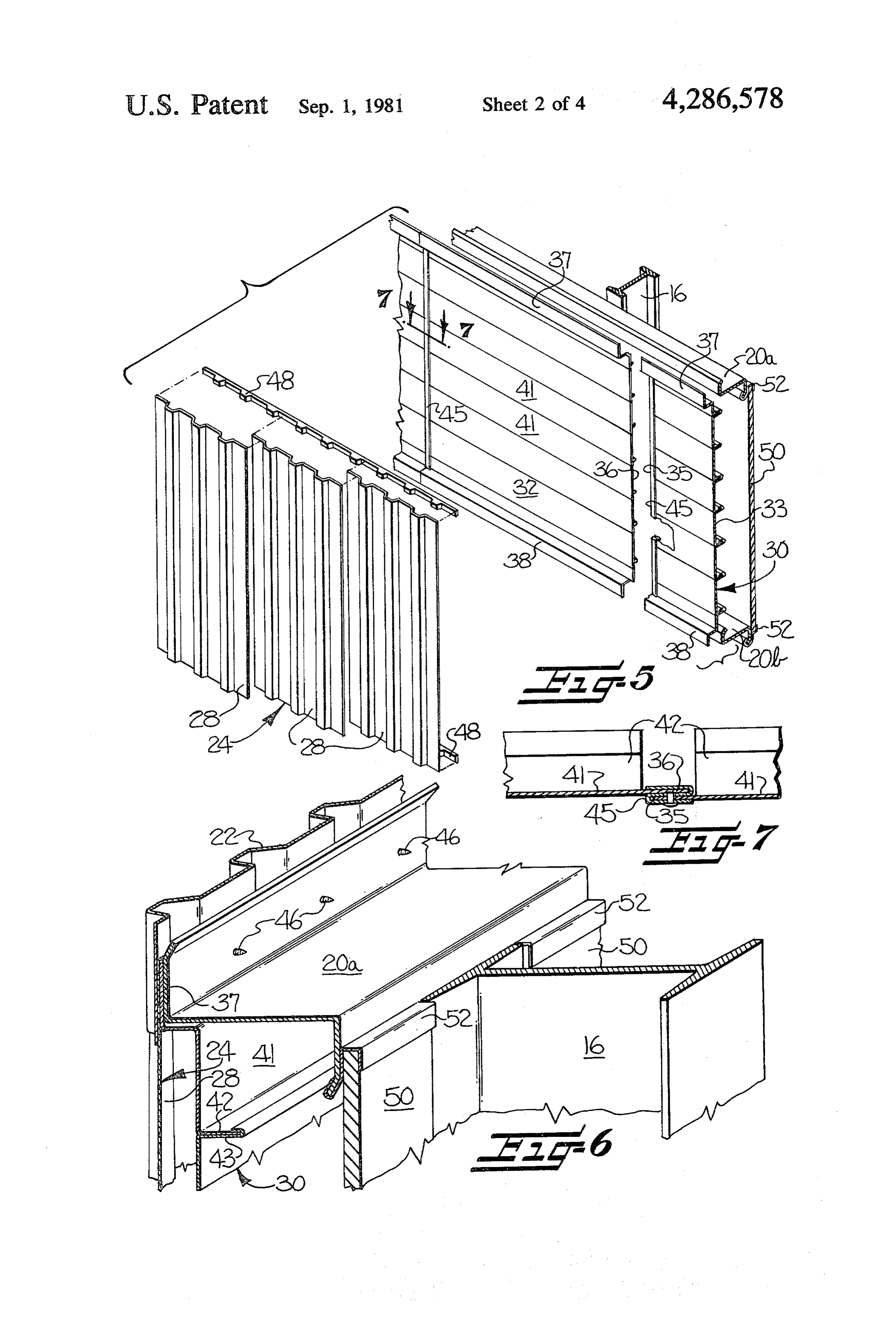
vantages is the high initial cost of the collectors, and the Some of the objects of the invention having been fact that expensive changes are often required in the stated, other objects will appear as the description pro building structure to accommodate the collectors. Also, 30 ceeds when taken in connection with the accompanying the collectors protrude from the normal exterior of the drawings, in which building, and are often unsightly. Still further, the solar FIG. is a perspective view, partly broken away, of energy absorptive panels presently utilized in such col a building structure embodying the present invention; lectors are relatively expensive, they cannot readily be FIG. 2 is a fragmentary perspective view of a portion formed into a collector surface of considerable length, 35 of the structural frame of a conventionai building struc and they are difficult to store or ship in view of their ture of the type illustrated in F.G. ; large size. FIG. 3 is a fragmentary sectional elevation view of a It is accordingly an object of the present invention to portion of the structural frame illustrated in FIG. 2, and provide a low cost solar energy absorptive panel which further illustrating the exterior panels; overcomes the above disadvantages. FIG. 4 is a fragmentary sectional elevation view of It is a more particular object of the present invention the building structure illustrated in FIG. and taken to provide a solar energy absorptive panel which may substantially along the line 4-4, and illustrating the be readily fabricated to a desired width, and which may solar energy collection apparatus of the present inven be interconnected to like panels to form a continuous tion positioned in the exterior wall thereof; collector surface of considerable length. FIG. 5 is a fragmentary exploded perspective view of It is a further object of the present invention to pro the solar energy collection apparatus shown in FIG. 4; vide a solar energy absorptive panel for a collecting FIG. 6 is a fragmentary perspective view of the por apparatus which may be built into the roof or exterior tion of the solar energy collecting apparatus indicated at wall of a standard building, such as a conventional pre 6 in FIG. 4;
fabricated metal building, and without changing the 5 FIG. 7 is a fragmentary sectional plan view illustrat normal contour of the exterior of the building. ing the structure by which the panels are intercon It is also an object of the present invention to provide nected, and taken substantially along the line 7-7 of a Solar energy absorptive panel for a collecting appara FIG. 5;
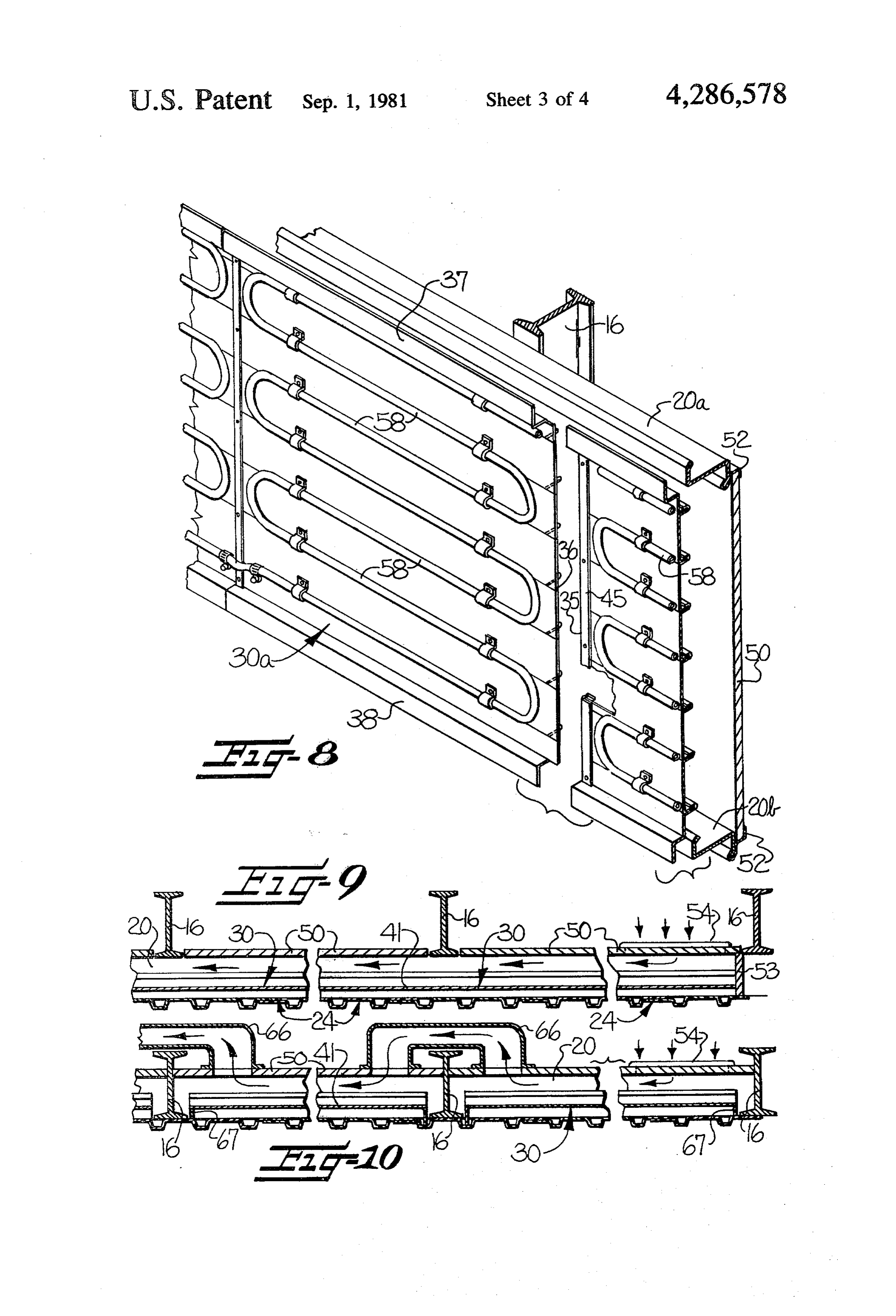
tus which utilizes certain of the structural components FIG. 8 is a fragmentary exploded perspective view of of a conventional building as part of the solar collector, 55 another embodiment of a solar energy collecting appa to thereby minimize the cost of the collector. ratus in accordance with the present invention; These and other objects and advantages of the pres FIG. 9 is a fragmentary sectional pian view illustrat ent invention are achieved in the embodiments illus ing the solar energy collecting apparatus of FIGS. and trated herein by the provision of a solar energy absorp 4-6;
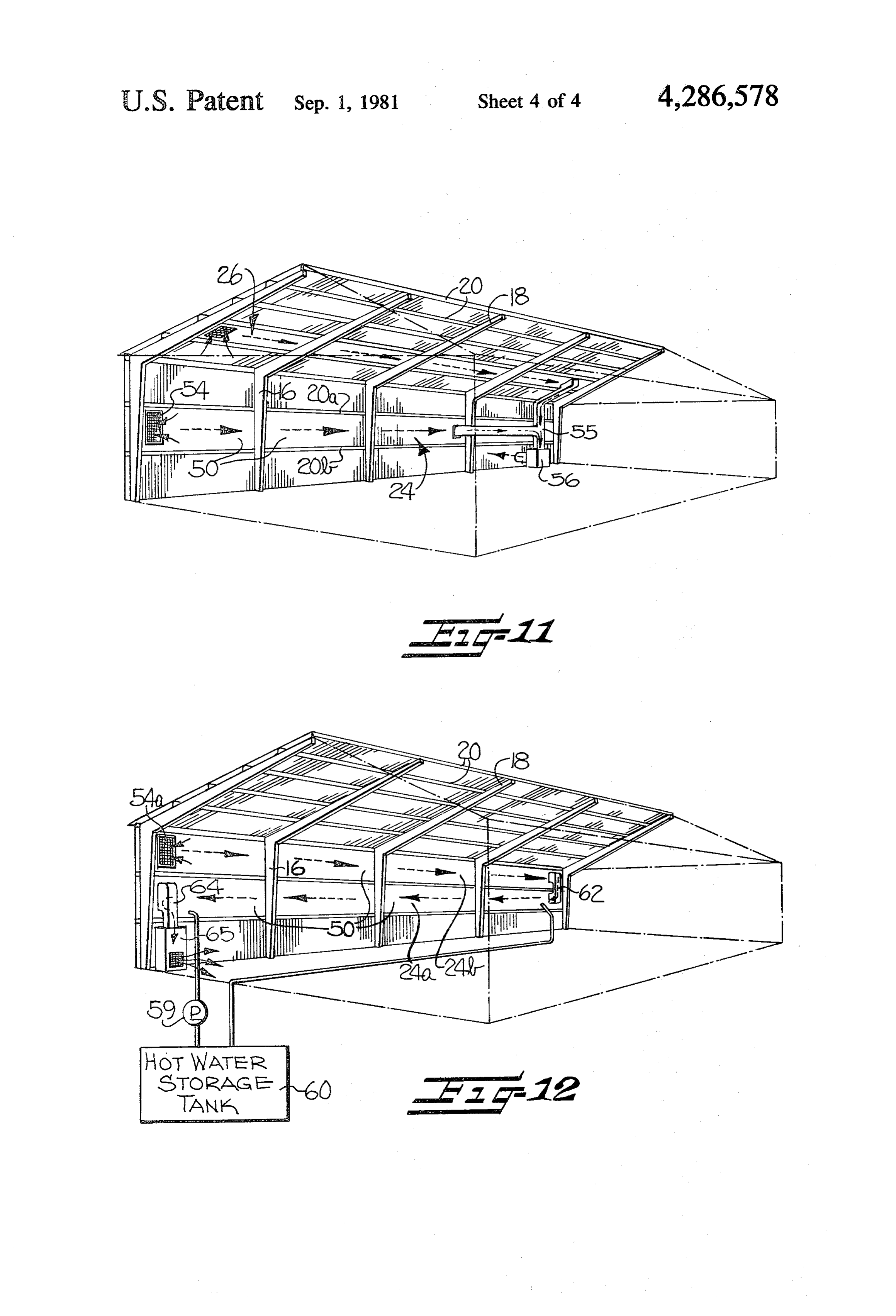
tive panel which comprises a sheet of metallic material 60 FIG. S is a view similar to FIG. 9 but illustrating having a dark coating overlying the outer surface another embodiment of the present invention and thereof, and a plurality of parallel fins integrally formed wherein the horizontal support members or purlins of from the material of the sheet and extending outwardly the building structure are disposed flush with the exte from the opposite surface thereof. The panel is com rior of the structural beams;
posed of a plurality of interconnected side-by-side U 65 FIG. is a fragmentary perspective view of the shaped sections, with the adjacent sides of the adjacent interior of the building illustrated in FIG. ; and U-shaped sections forming the fins. Slot means in the FIG. 12 is a view similar to FIG. S. but illustrating form of an S-shaped clip is mounted along one end edge another embodiment of the present invention and 7 wherein the vertical exterior wall incorporates two means comprises a plurality of individual, generally parallel solar energy collectors therein. rectangular panels 30 of a heat conducting material, Referring more specifically to the drawings, FIG. 1 such as 0.019 gauge diamond embossed aluminum sheet illustrates a building 15 which incorporates the solar ing. Each panel 30 defines a generally planar outer energy collecting apparatus of the present invention. surface 32 facing the transparent exterior panel, an op Certain structural components of the building are essen posite surface 33, and opposite end edges 35, 36, and tially conventional, and as indicated in FIGS. 2 and 3, opposite side edges 37, 38. The outer surface 32 is the conventional structural components include a plu coated with a dark, energy absorbing surface, such as rality of spaced apart vertical structural beams or col black paint. In addition, each panel 30 is composed of a umns 16 mounted on a foundation 7 and defining the 10 plurality of sections which extend between the end exterior periphery of the building. In addition, a number edges, with each section having a planar medial portion of inclined structural beams or rafters 18 are supported 41 and opposite sides 42, 43. The adjacent sides 42, 43 of by the columns 16 and define the roof of the building, adjacent sections extend substantially perpendicularly and a plurality of horizontal, spaced apart support men from the planar medial portion and are contiguous to bers or purlins 20 are attached to and extend perpendic 15 each other, to thereby form a plurality of fins extending ularly between the structural beams along the walls as outwardly from the opposite surface 33 of the sheet and well as the roof of the building. continuously between the opposite end edges 35, 36. The purlins 20 are essentially Z-shaped in cross-sec Also, the side 43 includes a reversely curved lip which tional configuration and are attached to the outside overlaps the extremity of side 42 to effectively intercon edges of the columns 16 and rafters 8. A plurality of nect the two sides. Typically, the fins are equally spaced rectangular exterior panels 22 are mounted in an over apart a distance of about 8 inches, and they are about 2 lapping, side-by-side arrangement to the outside edges inches in height. As will be apparent, the segmental of the purlins to form the exterior surface of the side construction of the panel permits it to be readily sized to walls and roof. Typically, the columns 6 are spaced almost any desired width by the addition of additional apart about 20 to 25 feet, and the purlins 20 are spaced 25 segments.
about 5 feet from each other. The exterior panels 22 Each panel 30 further includes slot means along the typically measure about 3 by 11 feet, and are fabricated end edge 35 for receiving the other end edge 36 of from a metallic or opaque plastic sheet material having another like panel therein, whereby a number of panels a corrugated cross-sectional configuration to improve may be readily joined in an end-to-end arrangement and the rigidity thereof. 30 with the fins extending in a common direction. As best In accordance with the embodiment of the present seen in FIG. 7, this slot means preferably comprises a invention as illustrated in FIG. , the wall and roof of clip 45 having an S-shaped cross-sectional configura the building 15 which face in a southerly direction each tion, with the clip being fixedly mounted along the end integrally incorporate a solar energy collector 24 and 26 edge 35 of the panel by a rivet or the like. If desired, the respectively, with the collectors being characterized by 35 fins of one panel may be laterally offset from the fins of the absence of components which protrude outwardly the adjacent panels to facilitate heat transfer to the beyond the contour of the building structure. While the adjacent airstream as further described below. wall collector 24 is described in detail herein, it will be The side edges 37, 38 of the panels 30 are offset in a appreciated that the roof collector 26 is of similar con common direction a distance of about one inch, such struction. that the offset side edge portions are coplanar with The wall collector 24 includes a plurality of exterior respect to each other and parallel to the plane of the panels 28 formed of a material transparent to solar radi outer surface 32. These offset side edge portions are ation and mounted to the outside edges of two adjacent adapted to be positioned upon the outside edges of the purlins 20a and 20b. The transparent exterior panels 28 purlins 2a, and 20b and thus underlie the overlapping are mounted in an overlapping side-by-side arrange 45 exterior panels 22 and 28 (note FIG. 6), and serve to ment along the length of the purlins, and they are pref provide an insulating air space between the exterior erably similar in cross-sectional configuration to the panels 28 and solar energy absorbing panels 30. The remaining exterior panels 22, such that the transparent overlapping exterior panelis 22 and 28 and panels 30 are panels 28 and remaining panels 22 are substantially co attached to the purlins 20a, 20b by means of selfthread planar and collectively define the exterior surface of the 50 ing screws 46 or the like, note FIG. 6. In this regard, a wall. Stated in other words, the transparent exterior side edge seal in the form of an elongate foam strip 48 panels 28 match the general appearance of the remain having a configuration corresponding to that of the ing panels 22 (with the exception of being transparent), exterior panel may be positioned intermediate the exter and thus they do not change the normal contour of the nal panels 28 and offset side edges 37, 38 of the panels 30 exterior of the building 15. As a particular example, the 55 to prevent passage of air therebetween and thus form a transparent panels 28 may comprise a conventional closed insulating airspace between the panels 28 and 30, plastic skylight panel, having a width of about 3 feet and note F.G. 5.
a length of about 5 feet so as to extend between the The wall collector 24 further includes interior panel purlins 20 and leaving a few inches to overlap the panel means mounted to the inside edges of the two purlins 22 positioned below, note FIG. 4. Where side-by-side 60 20a, 20b. This interior panel means is transversely collectors are employed as illustrated in FIG. 2, the aligned with the exterior panels 28, and comprises a panels 28 preferably are the normal 11 feet in length so plurality of individual, side-by-side panels 50 formed of as to extend across both collectors. a rigid fiberglass ductboard or similar material. The The collector 24 further comprises solar energy ab panels 50 may be attached by means of clips 52 which sorptive panel means mounted to extend between the 65 extend along the inside edges of the purlins 20a, 20b, or two adjacent purlins 20a and 2Gb and underlying sub by some other suitable means.
stantially the full area of the transparent exterior panels From the above description, it will be seen that the 28. More particularly, the solar energy absorptive panel solar energy absorbing panels 30, two purlins 20a, 20b, 8 and interior panels 50 collectively define an enclosed airlength of the wall or roof. Also, the panels 30 are con passageway which extends along the length of the wall. structed so as to terminate adjacent the columns, and a As best seen in FIG. 9, the interior panels 50 terminate closure partition 67 may be positioned along the end at the columns 16, and such that the outside faces of the edges of the panels to prevent air from entering the columns form a portion of the passageway. In addition, 5 insulating airspace between the panels 30 and exterior a suitable partition 53 is mounted between the purlins to panels 28.
close the ends of the passageway, as well as preclude In the drawings and specification, there has been set the entry of air between the exterior panels 28 and en forth a preferred embodiment of the invention, and ergy absorbing panels 30. By this arrangement, the pas although specific terms are employed, they are used in sageway is able to continue uninterrupted along the 10 a generic and descriptive sense only and not for pur entire length of the wall structure. Also, the fact that poses of limitation.
the purlins which form the side edge of the pasageway That which is claimed is: are part of the conventional building structure, results 1. A panel adapted for absorbing solar radiation in a in the cost of the collector being minimized. solar energy collector or the like and efficiently trans Means are provided for conveying air through the 15 ferring the absorbed heat energy to an airstream moving above described passageway, and as seen in FIG. 11, thereover, and comprising a generally rectangular sheet this conveying means comprises an inlet grill 54 at one of heat conducting material and having a generally end of the passageway and an air duct 55 and blower 56 planar first surface and an opposite surface, and oppo at the opposite end of the passageway. As illustrated, site end edges and opposite side edges, said sheet being the air duct and blower also communicate with the 20 composed of a plurality of interconnected side by side passageway of the roof collector 26. Also, it will be sections, with each section extending between said end apparent that the extent to which the side edges 37 and edges and including a planar medial portion and oppo 38 of the panels 30 are offset determines the volume of site sides, and with the adjacent sides of adjacent sec the passageway, and thus the offset may be designed to tions extending substantially perpendicularly from said provide the desired velocity of the air in the passage 25 planar medial portion and being contiguous and inter way for a given blower system. connected to each other to form parallel fins extending In operation, solar energy passes through the trans outwardly from the opposite surface of the sheet and parent exterior panels 28 of the two collectors 24, 26, between said opposite end edges, the outer sides of and warms the solar energy absorbing panels 30, and the those sections adjacent each of the opposite side edges air passing along the passageways contacts the finned of the panel being offset in a common direction, and surfaces 33 of the panels and absorbs heat therefrom. such that said offset sides are co-planar with each other The heated air may then be conveyed to a desired area and parallel to the plane of said first surface, and said of the building for heating purposes, or any other de panel further comprising slot means mounted along one sired use. of said end edges for receiving the other end edge of FIGS. 8 and 2 illustrate a modified embodiment of 35 another like panel therein and such that a plurality of the present invention wherein heat may be recovered panels may be readily joined in an end-to-end arrange from the solar energy absorptive panels 30a by means of ment and with said fins extending in a common direc a tubular conduit 58, such as copper tubing, mounted in tion, whereby the panel is adapted to transfer heat to air heat transfer relationship to the outside surface of the passing along said opposite surface in a direction paral energy absorptive panels 30a. Water may be conveyed 40 lel to said fins, and the panel may be readily fabricated through the tubular conduit by means of a pump 59, and from standard sized sections into a desired width. the heated water conveyed to a hot water storage tank 2. The panel as defined in claim 1 further comprising 60 or the like, note FIG. 12. Suitable controls (not a dark coating overlying said first surface to facilitate shown) may also be provided whereby either air flow the absorption of solar radiation thereby. through the passageway, or water flow through the 45 3. The panel as defined in claim 2 wherein one of each conduit 58 may be used to remove and recover the heat of said contiguous sides of adjacent sections includes a absorbed, or both systems may be operated concur reversely curved lip which overlaps the other of said rently. contiguous sides to effectively interconnect the same. FIG. 12 illustrates a further embodiment of the inven 4. The panel as defined in any one of claims 1-3 tion wherein collectors 24a, 24b substantially as de 50 wherein said slot means comprises a clip having an scribed above are provided between each of two verti S-shaped cross-sectional configuration, said clip being cally adjacent pairs of purlins. A transfer duct 62 is fixedly mounted along said one end edge of said panel. positioned between the collectors at one end thereof, 5. The panel as defined in claim further comprising whereby the air enters one collector through a grill 54a fluid conduit means attached in a heat conductive rela and passes through both collectors 24a and 24b before 55 tionship to said sheet, whereby the panel may be selec being withdrawn through the outlet duct 64 by blower tively used to transfer heat to air passing along said 65. opposite surface in a direction parallel to said fins, or to In certain conventional building structures of the a fluid passing through said conduit means. described type, the purlins are positioned within the 6. The panel as defined in claim 5 wherein said fluid outline of the structural columns 16 and so as to be flush 60 conduit means overlies said first surface. with the outside edges thereof. This construction is 7. The panel as defined in claim 1 wherein the panel illustrated in FIG. 10. The present invention may be is formed of a metallic heat conducting material and readily employed for use with such buildings by the use further has a dark coating overlying said first surface of transfer ducts 66 extending around the columns to thereof.
thereby form a continuous air passageway along the full 65 : & k xt
Provenance
- Collection
- Patents citing this work
- Pages
- 8
- Method
- pdftotext (the PDF's own text layer) + pdftoppm 300dpi page scans
- Patent office record
- patents.google.com →
- Source
- Google Patents citing-documents table
- Assignee
- Mcarthur William H
- Published
- 1981-09-01
- Transcribed from
- patentimages.storage.googleapis.com →