

patent · US4280325A
Unidirectional energy converter
28 July 1981
Text
Page 1bibliographic recordscan →
United States Patent (19)
Fawcett et al.
54 UNDRECTIONAL ENERGY CONVERTER
75 Inventors: Sherwood L. Fawcett, Columbus;
James N. Anno, Cincinnati, both of
Ohio 73 Assignee: Battelle Development Corporation, Columbus, Ohio
Related U.S. Application Data
abandoned, which is a continuation-in-part of Ser. No.
51 int. Cli................................................ FO3G 7/00 (52) as so a v 4 a 60/370; 60/721
3,859,789 1/1975 Fawcett et al. ................... 60/370 X 3,927,329 2/1975 Fawcett et al. . ... 60/325 X 4,117,696. 10/1978 Fawcett et al. .... ... 60/325 X 4,155,224 5/1979 Hopping et al..... ... 60/370 x 4,179885 12/1979 Hopping et al. ....................... 60/370 Primary Examiner-Allen M. Ostrager
Attorney, Agent, or Firm-Thomas H. Murray
Thermal energy is converted into rotational energy by
using the expansion of a fluid medium to propel a plural ity of pistons within at least one continuous, closed-loop passageway mounted on a rotatable platform. In at least one region of the passageway, the pistons must move inwardly against centrifugal force as the platform ro tates. In at least one other region of the passageway, the pistons are moved outwardly under the influence of centrifugal force. Means are provided for imparting force to successive ones of the pistons to propel them against centrifugal force in said one region; while means are provided for converting the energy of pistons mov ing outwardly under the influence of centrifugal force in said other region into rotational energy. This rota tional energy is used to drive gears mounted on the platform which mesh with a stationary gear carried beneath the platform to cause rotation of the platform about its rotational axis. The energy used to accelerate the pistons is thereby converted into rotational energy of the platform. In one embodiment of the invention, at least two continuous, closed-loop passageways are used on the platform in order to prevent an unbalanced con dition. In another embodiment of the invention, a single passageway is used on the platform comprising two essentially straight portions on opposite sides of the axis of rotation of the platform interconnected at their oppo site ends by curved portions, also on opposite sides of the axis of rotation of the platform. By forcibly rotating the platform in reverse, the invention can be used as a compressor.
40 Claims, 10 Drawing Figures
Drawings
Page 2drawing sheetscan →
Page 3drawing sheetscan →
Page 4drawing sheetscan →
Page 5drawing sheetscan →
Page 6scan →
support means for rotation about a central axis. At least
UNIDIRECTIONAL ENERGY CONVERTER one continuous, closed-loop passageway is carried by the platform and contains a plurality of freely-movable
CROSS-REFERENCES TO RELATED pistons. Means are provided for applying a force to APPLICATIONS 5 successive ones of the pistons in a first region of the This application is a continuation-in-part of copend passageway extending along the periphery of the rotat ing application Ser. No. 002,411, filed Jan. 11, 1979, ing platform to thereby propel each body in one direc now abandoned, which is a continuation-in-part of ap tion around the passageway and increase its kinetic plication Ser. No. 872,848, filed Jan. 27, 1978, now energy. In a second region of the passageway which abandoned. 10 curves inwardly toward the center of the platform the pistons, after being propelled, are caused to work
BACKGROUND OF THE INVENTION against centrifugal force to thereby convert the kinetic As is known, systems have been proposed in the past energy of the pistons into potential energy as they ap to convert one type of energy into another type by proach the center of rotation of the platform. In a third, using various thermodynamic cycles, such as the Otto, radially-extending region of the passageway centrifugal Rankine and Brayton cycles. Most of these systems force acts on the pistons causing them to move radially employ reciprocating pistons; although some, such as outwardly back to the first region. In the third region those shown in Dutch Pat. No. 65,164 and German Pat. the energy of the outwardly-moving pistons is con No. 842,845, employ one or more pistons which are verted into rotational energy which is then coupled to forced to travel in one direction in a continuous closed- 20 the platform to rotate the same. loop by the expansion of a gaseous medium in one re Preferably, in the embodiment of the invention just gion of the closed loop. In the closed-loop systems of described, there are two closed-loop passageways lo the prior art, each piston is coupled to a mechanical cated at diametrically-opposite locations on the rotating element which moves with it, the kinetic energy of the platform. Each passageway includes two arcuate seg moving piston being converted directly into mechanical 25 ments, each having a different radius, and a linear seg energy. These systems, however, require complicated ment interconnecting the two arcuate segments. When mechanisms for coupling the piston or pistons to an the apparatus of the invention is adapted for operation associated mechanical element. according to the Rankine cycle, a rotary union commu In U.S. Pat. No. 3,859,789, a method and apparatus nicates with a duct extending coaxially along a support are disclosed for converting one form of energy into 30 another form of energy through the use of a single shaft for the platform; while conduits extend from the continuous, closed-loop passageway containing a plu steam orthe duct to the first region of each passageway to supply like as the expansible fluid from a station rality of freely-movable, mechanically-unrestrained ary boiler. A second bodies which travel around the passageway in one di to each second regionduct can be connected by conduits rection only. Acceleration of the bodies is effected by 35 ing steam therefrom. The the of passageways for exhaust rotatable means for each pas means of an expanding fluid medium supplied externally sageway includes at least one but preferably two pock to the closed-loop passageway or by means of internal eted wheels disposed at opposite sides of the passage combustion. The kinetic energy of the bodies is ex way for receiving the pistons as they are moved radially tracted by a variety of methods including causing the outwardly along the propelled bodies, when formed from magnetically- 40 under the influence oflinear regions of the passageways centrifugal force. These pocketed permeable material, to pass through an electromagnetic field to convert some of the kinetic energy into electri wheels also serve to feed the pistons into the first region cal energy. Kinetic energy is also extracted by com where they are propelled by expansion of a fluid. The pressing the fluid between the bodies to provide energy turn, pocketed wheels are secured to arbors which are, in in the form of compressed fluid. When the expansion of 45 rotatably supported by the platform and coupled a gas is used to propel the bodies in this type of energy by gears in a stationary gear which is coaxial with the converter, the bodies pass through a region where the central axis of the platform. The rotational movement gas between them is compressed preparatory to a suc of the pocketed wheels is thereby converted into rota ceeding cycle of operation. In all such prior art systems tional movement of the platform. Typically, the pock of this type, the closed-loop passageway itself remains 50 eted wheels at opposite sides of the linear region of the stationary. passageway include circumferentially-spaced periph eral pockets to pass the pistons between the wheels.
SUMMARY OF THE INVENTION Alternatively, the wheels may have spaced-apart mag It is an object of the present invention to provide an nets on their peripheries, all of the magnets carried by improved unidirectional energy converter in the form 55 one wheel having magnetic south poles and those car of a rotating engine wherein pistons are accelerated ried by the other wheel having magnetic north poles at around a closed-loop passageway mounted on a rotat their respective peripheries.
ing platform. Energy in the form of an expanding gas is When the aforesaid embodiment of the invention is converted into kinetic energy which is then converted adapted for operation according to the Brayton cycle, into potential energy by working the pistons against the 60 liquid fuel is fed from a stationary tank through a coax centrifugal force of the rotating platform. Finally, the ial pipeline to the rotating platform. An inlet manifold pistons are moved radially outwardly on the platform and an exhaust manifold communicate with only part of under the influence of centrifugal force; and their en the opposite sides of the aforesaid second arcuate region ergy is converted into rotational energy which is used of each passageway. The remaining part of the second to rotate the platform and provide useful work. 65 region is used to compress air between the bodies. The In accordance with one embodiment of the invention, compressed air is then fed to a combustion chamber the apparatus for converting a first form of energy into where it is heated and used to propel the pistons in the a second form of energy includes a platform carried by first region of each passageway.
Page 7scan →
In another embodiment of the invention, a single passageway where pistons are propelled against centrif passageway, rather than two, is provided on the rotat ugal force;
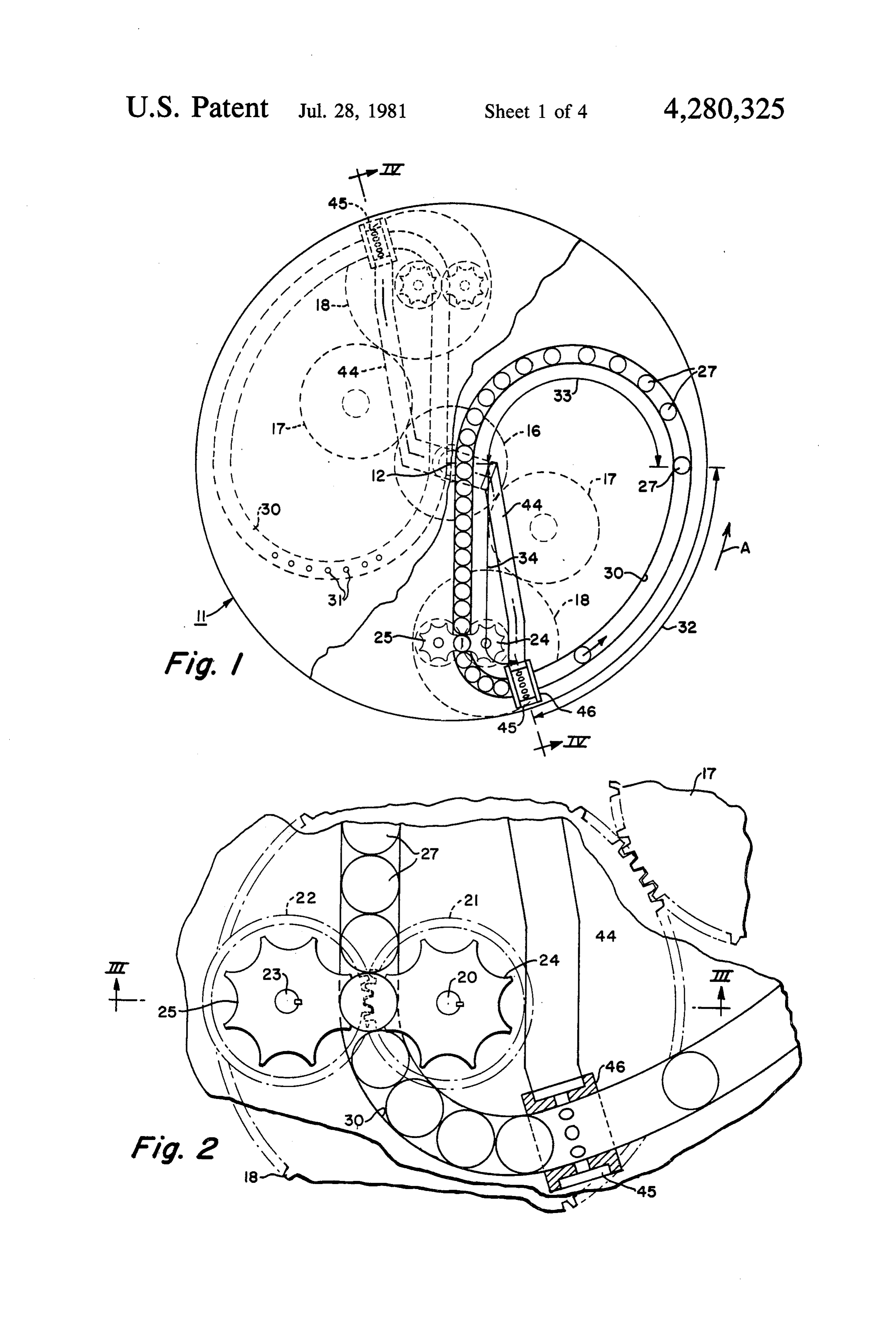
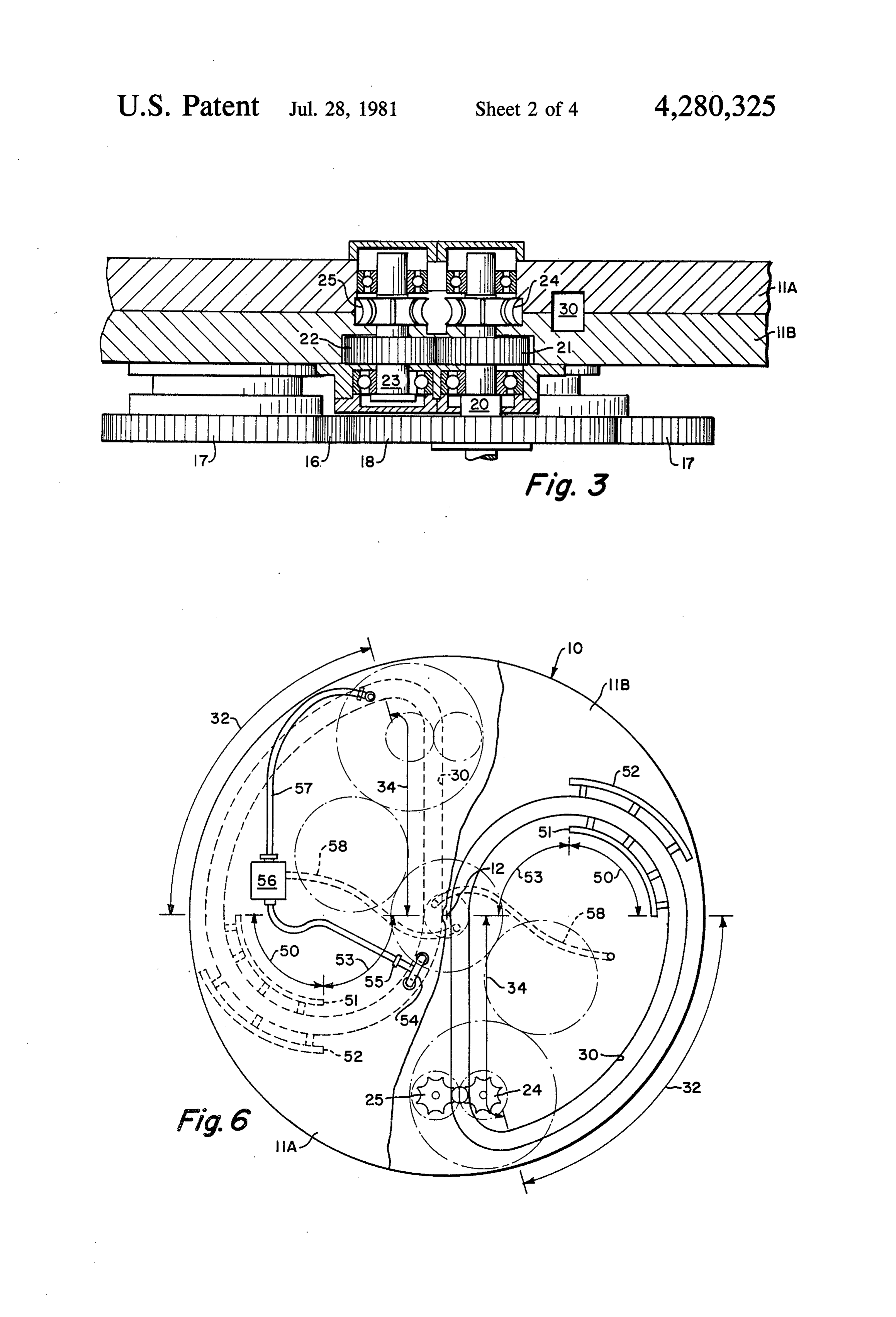
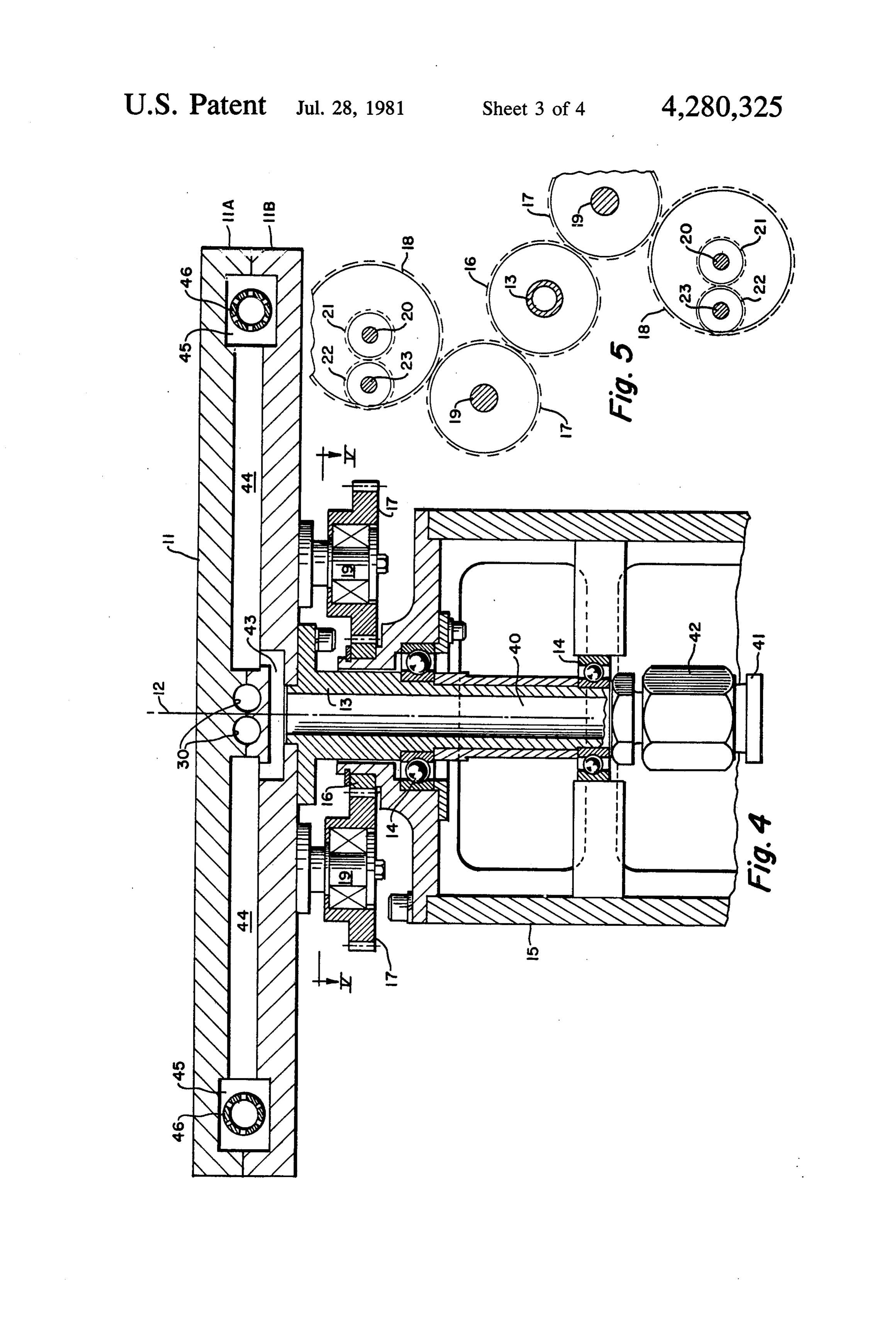
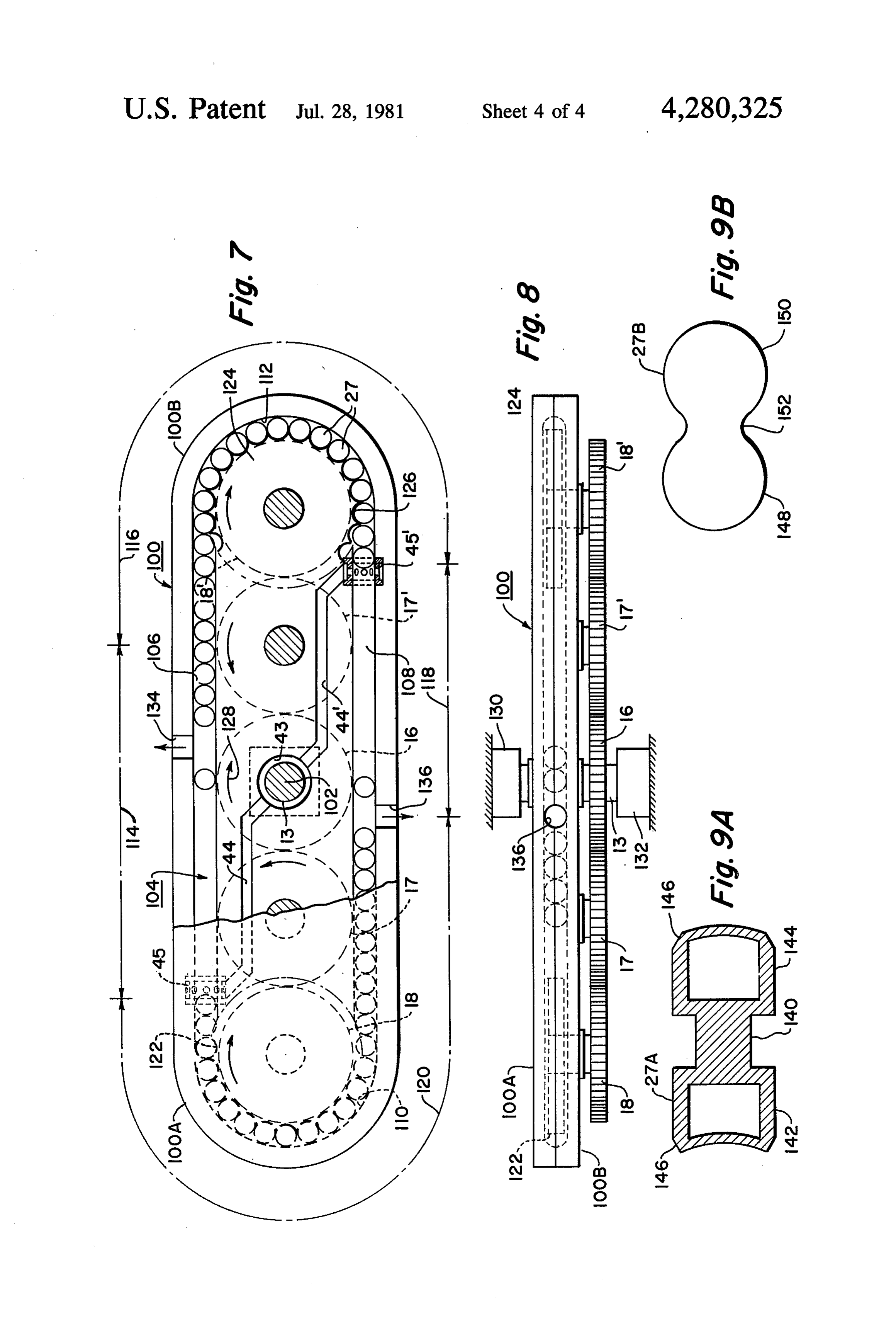
able platform. In this case, the passageway has straight FIG. 8 is a side view of the embodiment of the inven portions on opposite sides of the central axis of rotation tion shown in FIG. 7; and of the platform, the straight portions being intercon FIGS. 9A and 9B illustrate alternative forms of the nected at their ends by curved portions, also on oppo pistons which can be used in the two embodiments of site sides of the central axis of rotation of the platform. the invention.
Means are provided for applying a force to successive With reference now to FIGS. 1-5, the rotating engine ones of the pistons in one region in each of said straight shown includes a platform 11 in the form of two disc portions of the passageway to propel them inwardly on O shaped plates 11A and 11B (FIGS. 3 and 4) with mutu the rotating platform against centrifugal force, the pis ally-engaging face surfaces maintained in contact by tons being moved radially outwardly in another region fastening members, not shown. The platform is adapted of each of the straight portions under centrifugal force. to rotate about a central vertical axis 12 (FIG. 4) and is The means for converting the energy of the pistons into secured by fasteners to a centrally-arranged shaft 13 rotational energy comprises pocketed wheels having 5 extending downwardly from the bottom of plate 11B of their peripheries coinciding with the inner peripheries the platform. Bearings 14 support the shaft 13 for rota of the curved portions of the passageway to convert the tion within a support frame 15. A stationary main gear energy of the pistons in the curved portions, which 16 is keyed to a journal surface provided on frame 15. have been moved outwardly under centrifugal force, As is perhaps best shown in FIGS. 1 and 5, the diameter into rotational energy. As in the previous embodiment, of gear 16 is selected so that it meshes with two separate these pocketed wheels are coupled through a gear train gear trains, each being identical and including a first mounted on the platform which meshes with a station idler gear 17 and a second idler gear 18. The gears 17, ary gear carried beneath the platform to cause rotation for example, are supported by bearings on arbor shafts of the platform about its rotational axis. 19 (FIGS. 4 and 5) carried by plate 11B. It will be appreciated from the following description As shown in FIGS. 2, 3 and 5, each idler gear 18 is that by driving the rotating platform of the invention in secured to the lower end of an arbor shaft 20 which reverse, the device can be used as a compressor rather extends through an opening in the platform 11. Above than an engine. In this case, rotational energy is con gear 18, the arbor shaft 20 carries a timing gear 21 lo verted into compressed gas with the aforesaid pocketed cated within a recess in plate 11B. In this recess, the wheels forcing the pistons radially inwardly in the 30 timing gear 21 meshes with a second timing gear 22 closed-loop passageway. The pistons are then forced secured to an arbor shaft 23. Both arbor shafts 20 and 23 radially outwardly; while air is drawn into the passage rotate in suitable bearings supported by the platform as way through the ducts which function as exhaust ports shown. The upper ends of arbor shafts 20 and 23 carry during operation as an engine. The radially-propelled pocketed wheels 24 and 25, respectively. As shown in pistons then move back to the pocketed wheels while 35 FIGS. 1 and 2, the pocketed wheels have circular reces they compress air which is expelled through the duct ses uniformly spaced about their outer periphery which which acts as an intake port during operation as an are adapted to receive in succession pistons 27 which engine. are typically spheroids.
Finally, it will be appreciated that a number of rotat The respective pairs of pocketed wheel assemblies 24, ing platforms of the type described above can be coaxi 25 are arranged at generally, diametrically-opposite ally mounted on, and secured to, a single shaft such that locations on the platform 11. Each pair of pocketed a number of energy converters effectively operate in wheels forms part of an independent, unidirectional parallel. energy converter loop that includes a continuous, The above and other objects and features of the in closed-loop passageway 30. The two loop passageways vention will become apparent from the following de 45 take the form of machined slots in each of the mutually tailed description taken in connection with the accom engaging face surfaces of the plates 11A and 11B of the panying drawings which form a part of this specifica platform 11. In other words, the passageway 30 is de tion, and in which: fined by aligned slots having walls which are preferably FIG. 1 is a plan view of the rotating engine according smooth and formed from metal. The passageways are to one embodiment of the present invention for convert 50 located at mutually-exclusive sectors which lie at oppo ing, according to the Rankine cycle, one form of energy site sides of a vertical plane passing through the axis 12. into a second form of energy; The pistons 27 are freely-movable bodies which pass in FIG. 2 is an enlarged plan view of the pocketed succession through each passageway. The tolerances or wheels of the invention for feeding pistons forming part clearances between the surfaces of the pistons 27 and of the apparatus shown in FIG. 1; 55 the walls of the passageway 30 are such as to permit the FIG. 3 is a cross-sectional view taken along line III pistons to move freely therealong. Fluid flow past the -III of FIG. 2; pistons within the passageways is substantially pre FIG. 4 is a sectional view taken along line IV-IV of vented since the pistons have a spherical shape which is FIG. 1; substantially complementary to the cross-sectional FIG. 5 is a sectional view taken along line V-V of shape of the passageways. If desired, a tube can be used FIG. 4; as a liner in each passageway. FIG. 6 is a plan view similar to FIG. 1 but illustrating As shown in FIG. 1, each passageway 30 is made up the apparatus of the present invention for operation of three regions 32, 33 and 34. Region 32 extends along according to the Brayton cycle; the periphery of the platform 11 for a distance of ap FIG. 7 is an illustration, in partially broken-away plan 65 proximately 90'. This region forms an expanding sec view, of another embodiment of the invention wherein tion wherein a fluid medium, such as steam, is used to a single loop passageway extends around the axis of freely accelerate the pistons in succession. Region 33 is rotation of a platform, there being two regions in the curved inwardly toward the center of rotation of the 8 platform 11 and is provided with one or more ports 31 gal force; and as they pass through the pocketed wheels in the upper plate 11A to bleed off fluid between succes 24 and 25, torque will be imparted to the pocketed sive pistons. It should be understood, however, that the wheels which is coupled through gears 21, 17 and 18 to ports 31 could be replaced by a plenum chamber which the stationary gear 16. The energy of the pistons, which collects the steam, condenses and returns it to a boiler. 5 are urged radially outwardly by centrifugal force in As the pistons 27 move radially inwardly in the re region 34, is thus converted into rotational energy used gion 33, they must work against centrifugal force; and to drive the platform 11 in the direction of arrow A as in this process the kinetic energy of the moving pistons shown in FIG. 1. It will be appreciated that a starter in region 32 is converted into potential energy as they motor or some other device to initially rotate the plat approach the center of rotation of the platform. Finally, 10 form may be required to initiate centrifugal force on the when the pistons are in region 34 in closely-abutting pistons in region 34.
relationship, they are urged radially outwardly under In addition to converting the energy of the pistons the influence of centrifugal force. In this process, they into rotational energy, the gear system just described pass through the pocketed wheels 24 and 25, thereby has two other functions. The second function is to main inducing rotation which is transmitted through idler 15 tain the entire rotating system of the rotating energy gears 18 and 17 to central gear 16, thereby causing the converter at a desired velocity. The third function of entire platform 11 and the elements carried thereby to the gear system is to feed the pistons into the expander rotate in the direction indicated by the arrow A in FIG. region 32 and provide thrust to overcome frictional 1. As the pocketed wheels 24 and 25 rotate, they feed drag of the pistons in the loop passageway. successive ones of the pistons 27 to the first or expander 20 The two unidirectional energy converter loops ac region 32 where they again are propelled in a direction cording to the invention are disposed at mutually-exclu opposite to the direction of rotation of the platform 11. sive sectors which are spaced 180’ from each other and In FIGS. 1-5, steam is used for the operation of the supported by the platform 11. While it is possible to use. rotary platform according to a Rankine cycle. The a single closed-loop passageway, it is obviously prefera steam is fed from a stationary boiler, not shown, to the 25 ble to use at least two diametrically-opposed passage rotating platform 11 by means of a duct 40 (FIG. 4) ways in order that the rotating platform 11 will be bal extending through the support shaft 13. The steam is anced rotationally. Furthermore, it will be appreciated delivered by a stationary conduit 41 through a rotary that a series of platforms such as that shown herein may union 42 and into the duct 40. Duct 40 communicates be stacked in spaced-apart relation for rotation about a with a chamber 43 located in the plate 11B below the 30 common axis 12.
continuous, closed-loop passageways 30. Radially A practical engine incorporating the principles of the extending slots 44, machined into the mutually-engaged invention may, for example, employ a three-foot diame face surfaces of plates 11A and 11B, deliver the steam ter platform having a thickness twice the diameter of from chamber 43 to supply chambers 45 (see also FIGS. the pistons 27. The rotating engine may incorporate ten 1 and 2). Disposed within the chambers 45 are bushings 35 unidirectional energy conversion loops having pistons 46 with portal openings to deliver steam from the slots with diameters of 1 inches. Such an engine will de 44 into the expander region 32. As shown, the expansi velop approximately 50 horsepower while the overall ble steam is injected into the expander region at the size of the engine will be about three feet in diameter point of juncture between the expander region 32 and and about one foot long, not including ducting for the the radially-extending region 34. The force exerted by steam and exhaust. Under these circumstances, the fre the expanding steam propels the pistons along the ex quency of the pistons in the passageways would be pander region to the point where they enter the com about 100 per second while the platform rotates at a bined coasting and steam exhaust section formed by speed of about 650 revolutions per minute. Such a con region 33. In region 33, the steam is exhausted through cept for a rotating engine has a significant potential for ports 31 to the atmosphere as described above or, if 45 practical low-temperature steam engines based on a 66 desired, a system of ducts may be used to conduct the psia at 300' F. steam inlet pressure and a 3 psia at 140" steam and/or condensate from region 33 through a pipe steam outlet pressure.
within duct 40 in shaft 13 for return to the boiler. FIG. 6 illustrates another embodiment of the inven In the operation of the invention, the steam injected tion incorporating the principles of the Brayton cycle. into the expander region 32 will propel each of the 50 Because of the similarity between the parts forming the pistons 27 along the periphery of the platform 11, rotating engine for a Brayton cycle and the parts form thereby converting the thermal energy of the steam into ing a rotating engine for operation according to the kinetic energy of the pistons 27. As each of the pistons Rankine cycle as just described, elements of FIG. 6 27 is propelled forwardly, an equal and opposite reac which correspond to those of FIG. 5 are identified by tion is induced tending to rotate the platform in the 55 like reference numerals. The expander region 32 of each direction of arrow A. However, as the pistons 27 enter continuous, closed-loop passageway 30 curves along a the region 33, their direction of movement changes, 90 circumferential part of the platform 11. A combined thereby producing a force on the platform 11 tending to exhaust and intake section 50 receives the pistons from rotate it in a direction opposite to the direction of arrow the expander region 32. An exhaust manifold 51 delivers A. The two forces thus produced essentially cancel the exhaust gases carried between successive pistons. each other so that, as the pistons are propelled around The exhaust gases are replaced by fresh air from an inlet the passageway 30, the net torque on the platform 11 is manifold 52. From region 50, the pistons pass into a essentially zero. As the pistons pass through region 33 compression region 53. The gases compressed between and work against centrifugal force, their kinetic energy the pistons are delivered by a manifold 54 at an in is converted into potential energy as they enter the 65 creased pressure through a check valve 55 and into a radially-extending region 34. Now, and assuming that combustion chamber 56. The compressed air is heated the platform 11 is rotated, the abutting pistons 27 in in the combustion chamber and introduced into the region 34 will be urged radially outwardly by centrifu unidirectional energy conversion loop by an inlet con 9 duit 57. The heated air accelerates the pistons in succes thruster region 116, a second expander region 118 and a sion along the expander region 32. Liquid fuel is fed second thruster region 120. Rotatable thruster wheels from a stationary tank on the rotating platform through 122 and 124 are mounted for rotation on the platform at a coaxial pipe in shaft 13 with a rotating shaft seal. The the respective axes of the two curved end portions 110 fuel is then fed by a conduit 58 into the combustion 5 and 112 of passageway 104. The thruster wheels 122 chamber 56. and 124 are provided with pockets 126, uniformly As each piston exits from the expander region 32 in spaced about their outer peripheries, which are adapted succession, the velocity of the piston is at a maximum to engage successive pistons 27 through the open inner relative to the unidirectional energy conversion loop faces of the curved end portions 110 and 112 of the formed by its passageway 30. The kinetic energy of the O passageway 104. As the pocket thruster wheels 122 and piston is thus converted into potential energy as the 124 rotate, they serve to move successive pistons pistons approach the center of the rotating platform 11 through the curved end portions 110 and 112 and into in passing through arcuate regions 50 and 53. The ki the respective expander regions 114 and 118. The rotat netic energy of the piston is also expended by compres ing thruster wheels also serve to drive the rotating plat sion of air to form the compressed air supply which is 15 form 100 and the shaft 13 connected thereto through fed into the combustion chamber and then, when central, stationary main gear 16 and appropriate idler heated, fed into the expander inlet. In the radially gears 17 and 17" located beneath the platform 100. Idler extending region 34 of the passageway, the pistons gears 17 and 17", in turn, mesh with gears 18 and 18 apply centrifugal force to the pocketed wheels. The connected to the rotatable pocket wheels 122 and 124, mechanical power formed by the unidirectional energy respectively, as best shown in FIG. 8. Thus, as the conversion loop is the net centrifugal force imparted to pocket wheels 122 and 124 rotate in the direction of the the platform through the sprocket-gear train. arrows shown in FIG. 7, torque will be transmitted to The second unidirectional energy conversion loop the shaft 13 to cause it and the platform 100 connected supported by the platform 11 in FIG. 6 is identical to thereto to rotate in the direction of arrow 128. The shaft the first and positioned diametrically opposite the first 13 may be conveniently journaled in bearings 130 and loop. It is again apparent that a series of platforms 11 132 as shown in FIG. 8.
may be stacked in superimposed spaced-apart relation In the operation of the embodiment shown in FIGS. along the same axis 12. Thus, the unidirectional energy 7 and 8, an ideal diatomic gas (e.g., air or steam) at a conversion engine operating according to the Brayton pressure elevated above ambient (i.e., from a compres cycle may consist of multiple unidirectional energy sor, boiler or the like) is introduced into the passageway conversion loops as was the case with the embodiment 104 via inlet port 45 located between the second of FIGS. 1-5. thruster region 120 and the first expander region 114, FIGS. 7 and 8 illustrate another embodiment of the and via inlet port 45' located between the first thruster invention wherein a single passageway is utilized on a region 116 and the second expander region 118. Gas is rotating platform rather than two passageways as in the 35 exhausted from the passageway via a venting port (or embodiment of FIGS. 1-6. Since many of the parts ports) 134 located between the first expander region 114 forming the rotating engine of the embodiment of and the first thruster region 116, or via port (or ports) FIGS. 7 and 8 are the same or similar to those of FIGS. 136 located between the second expander region 118 1-6, certain elements of FIGS. 7 and 8 which corre and the second thruster region 120. The pistons 27 act as spond to those of FIGS. 1-6 are identified by like refer- 40 porting valves at the inlet and venting ports as in the ence numerals. embodiment of FIGS. 1-6. Passageways of slots 44 and In the rotating unidirectional energy converter 44' can be provided to deliver steam or another expansi shown in FIGS. 7 and 8, a platform 100 is provided ble fluid from chamber 43, similar to chamber 43 shown which rotates about a central axis 102. The platform 100 in FIG. 4, to the inlet ports 45 and 45. is elongated but symmetrical about the axis of rotation 45 The pressurized gas entering the first expander region 102 and is, therefore, balanced about the axis of rota 114 through inlet port 45 drives successive pistons 27 tion. The platform 100 can be formed from upper and through the expander region 114 against the centrifugal lower halves 100A and 100B as shown in FIG. 8. force field generated by rotation of the platform 100. Formed in the upper and lower halves 100A and 100B That is, the pistons must work against centrifugal force is a single continuous, closed-loop passageway 104 hav- 50 as they approach the center of rotation of platform 100. ing two straight portions 106 and 108 on opposite sides When the next piston closes off the inlet port 45, the of the axis of rotation 102. The opposite ends of the unit cell of gas between the pistons is closed off from the straight portions 106 and 108 are interconnected by inlet port 45 and expands adiabatically as the lead piston curved portions 110 and 112, respectively, the portions moves through the expander region. When the piston 110 and 112 also being on opposite sides of the axis of 55 ahead of the piston in the expander region 114 traverses rotation 102 of the platform 100. Thus, opposite sides of venting port 134, the unit cell of gas ahead of the piston the passageway 104 are arranged symmetrically, and still in the expander region 114 is exhausted through the balanced, about the axis of rotation 102. The platform venting port. The piston in the expander region then 100 is generally elliptical in shape, meaning that it is arrives at the beginning of the thruster region 116 and long as compared to its width, having semicircular end 60 closes off the venting port 134; while the ensuing piston portions connected by straight portions. Instead of is driven through the expander region in accordance forming the passageway 104 from upper and lower with the cycle just described.
plates 100A and 100B, it is also possible to form the Upon leaving the expander region 114, the piston passageway from a tube which is rigidly mounted on a enters the thruster region 116 which is filled with pis rotatable platform, not shown. Other forms of construc- 65 tons. When the pistons are in the thruster region, in tion will be readily apparent to those skilled in the art. closely-abutting relationship, they are urged toward the The loop passageway 104 is made up of four regions. curved end portion 112 of the passageway 104 under These comprise a first expander region 114, a first the influence of centrifugal force. That is, they are 10 urged outwardly in relation to the axis of rotation 102 of duits via the inlet ports. After expansion, the gas is the platform 100 by centrifugal force. In this process, exhausted at ambient pressure via the venting ports 134 they engage the pocketed thruster wheel 124 and impart and 136 either directly to the atmosphere or through a torque thereto, causing it to rotate with the rotation coaxial duct. The compressed gas may be obtained via being transmitted through gears 18' and 17 to central conventional compressor means, either stationary or gear 16, thereby causing the entire platform 100 and the rotating on the platform; however, it is preferred to drive shaft 13 to rotate in the direction indicated by obtain the compressed gas from a separate unidirec arrow 128 in bearings 130 and 132 (FIG. 8). The energy tional energy converter loop which is rotating about the of the pistons, which are urged outwardly by centrifu same axis of rotation (i.e., stacked above or below the gal force in regions 116 and 120, is thus converted into 10 platform), and which is adapted to function as a com rotational energy of the platform. Instead of using gears pressor in the manner described in connection with as in the embodiment shown in FIGS. 7 and 8, it is, of FIGS. 7 and 8 hereinafter or as described in U.S. Pat. course, also possible to utilize drive chains or other No. 3,859,789, Fawcett et al.
suitable means in accordance with well-known tech In the operation of the embodiment of FIGS. 7 and 8 niques. 15 in accordance with the principles of the Diesel cycle, an As the thruster wheels 122 and 124 rotate, they feed expanding gas is provided in the expander regions by successive ones of the pistons to the expander regions way of internal combustion within these regions. Com 114 and 118 where the cycle described above is re pressed air (typically from one of the sources described peated. In addition to converting the energy of the above in reference to the Brayton cycle) is introduced pistons 27 into rotational energy, the gear system de 20 into the regions via the inlet ports 45 and 45. Liquid or scribed above has two other functions. The second gaseous fuel is fed into the expander regions 114 and 118 function is to maintain the entire rotating system of the when the inlet ports are closed off by the pistons leaving rotating energy converter at a desired velocity. The the thruster regions. Combustion takes place in the. third function of the gear system is to feed the pistons expander regions and is cycled to effect expanding gas into the expander regions 114 and 118 and to provide 25 behind each piston as it enters the expander regions 116 thrust to overcome frictional drag of the pistons in the and 120. That is, combustion takes place periodically to loop passageway. propel successive ones of the pistons through the expan It can thus be seen that the rotating passageway 104 der regions. As with the Brayton cycle, the combustion of the embodiment of FIGS. 7 and 8 comprises, in se gases may be exhausted at ambient pressure via the ries, a first expander region 114, a first thruster region 30 venting port directly to the atmosphere or through a 116, a second expander region 118 and a second thruster coaxial duct.
region 120. This is in contrast to the embodiments The operation of the embodiment of FIGS. 7 and 8 shown in FIGS. 1-6 wherein each passageway com according to the Otto cycle is similar to that described prises only one expander region and one thruster re above regarding the Diesel cycle. The fuel and air may gion. However, except as noted above, this embodiment 35 be separately introduced into the expander regions, as in functions in a manner generally similar to the embodi the Diesel cycle, or the fuel may be mixed with the ments previously discussed. A starter motor or some incoming air before or after it is compressed. Ignition of other device to initially rotate the platform 100 may be the fuel-air mixture is effected in the expander regions required to initiate centrifugal force on the pistons in 114 and 118 by means of a conventional spark system regions 116 and 120. located in an appropriate recessed area in these regions. In the embodiment shown in FIGS. 7 and 8, steam As in the Diesel cycle, combustion is cycled to effect may be used for the operation of the rotating platform expanding gas successively behind each piston as it 100 in accordance with the Rankine cycle as in the passes so as to propel successive ones of the pistons previously-described embodiments. When steam is through the expander regions.
used, the force exerted by the expanding steam, which 45 If the platform 100 shown in FIGS. 7 and 8 is rotated enters the passageway 104 through ports 45 and 45, by a motor or some other external power source in a propels the pistons 27through the expander regions 114 direction opposite that shown, gas at ambient pressure and 118. The steam is exhausted through venting ports will be taken into the passageway 104 via ports 134 and 134 and 136 as the pistons enter the thruster regions 116 136 and will be exhausted at an elevated pressure via and 120. Venting ports 134 and 136 may be open to the 50 ports 45 and 45'. In this regard, the system can function atmosphere or, if desired, a system of ducts, not shown, as a compressor. If the platform 100 is rotated by a may be used to return the steam and/or condensate to motor, the system of gears interconnecting the thruster the boiler in a manner similar to that of FIG. 4. wheels 122 and 124 to the central shaft 13 will act to While the rotating engine as shown in FIGS. 7 and 8 rotate the thruster wheels. The rotating thruster wheels may operate in accordance with the thermodynamic 55 will then move the stacked pistons 25 in the thruster principles of the Rankine cycle as described above, this regions toward the axis of rotation of the platform, so embodiment of the invention, appropriately modified, that upon passing ports 134 and 136, the pistons will may also function in accordance with the principles of travel through the expander regions 114 and 118 under the Brayton, Diesel, or Otto cycles as briefly described the influence of centrifugal force. The gas between the below. 60 pistons will be adiabatically compressed by the moving In the operation of the embodiment of FIGS. 7 and 8 pistons in the expander regions 116 and 120 which according to the Brayton cycle, compressed gas (typi would more properly be termed "compressor regions' cally air) is heated in a combustion chamber rotating on in this mode.
the platform as in FIG. 6, or by a heat exchanger rotat It will also be appreciated that a series of unidirec ing on the platform, with the heat exchanger being 65 tional energy converters may be stacked in superim connected to a stationary external heat source via a posed, spaced-apart relation for rotation upon shaft 13 coaxial duct. The heated, compressed gas is then intro about the common axis 102. In the embodiment of duced into the expander regions from appropriate con FIGS. 7 and 8, the following general observations can 11 be made: (1) the change in enthalpy of the gas in the rate drive motor to independently drive the platform, expander regions produces net work, which is per the rotating engine of the present invention can be uti formed on the thruster wheels 122 and 124 via the pis lized to produce torque independently from engine tons 27, and then transmitted to the rotating platform drive shaft speed (i.e., high torque can be produced at 100 and the shaft 13; (2) the change in enthalpy of the low or variable speed).
gas in the expander regions transfers energy via the As was explained in the introductory portion of the centrifugal field (potential) energy stored in the mass of specification, it is also possible to use the various en the pistons as they move through the expander regions bodiments of the invention previously described as from a larger radius of rotation (i.e., about the axes of compressors. In the embodiment shown in FIGS. 1-5, rotation of the platform 100) to a smaller radius of rota O for example, the platform 11 can be rotated in a direc tion (i.e., nearer the axis of rotation); (3) the initial and tion opposite to that indicated by arrow A, in which final velocities of the pistons traveling in the expander case the pocketed wheels 24 and 25 will force the pis regions relative to the rotating platform are equal; and (4) the inlet and venting gas port sizes, the mass of the tons 27 radially inwardly along region 34. In region 33, pistons, the speed of rotation of the thruster wheels and 15 the air pistons are forced radially outwardly while drawing into the passageway 30 through ports 31. The pistons the platform, and the inlet and exit states of the gas are 27, propelled radially outwardly by centrifugal force, all interrelated in the operation of, and the net work then travel through region 32 and in so doing compress produced in, this system. Under some conditions of the air between successive ones of the pistons such that operation, the gas pressure in the expander region dur their kinetic energy is converted ing part of the operating cycle may be below ambient. 20 The compressed gas then exits into the compressed gas.
passageway 30
In FIGS. 9A and 9B, alternative forms of the pistons 27 are shown. In FIG. 9A, the piston 27A comprises a through the portal openings in the bushing 46 and is body having a central annular slot 140 and large diame conveyed through slot 44 to the duct 40. The platform 11 may be driven by suitable gearing ter end portions 142 and 144 provided with spherically beveled edges 146 which can engage the periphery of 25 coupled to the shaft 13, by gearing which meshes with the passageway 104 as the pistons 27A pass around the a ring gear carried on the periphery of the platform 11, curved portions 110 and 112. The large diameter por or by a shaft which is coaxial with shaft 13 on the oppo tions 142 and 144 are hollow as shown. The configura site side of the platform 11. The same alternatives are tion shown in FIG. 9A comprises, in effect, two inter possible to derive rotary energy from the device when connected pistons separated by the reduced diameter 30 used as an engine. When plural energy conversion de portion 140 which receives the radially, outwardly vices are employed in superimposed spaced-apart rela projecting prongs on the pocketed wheels 122 and 124 tion along the same axis 12, they may be interconnected as the pistons move around the curved portions 110 and by means of the hollow shaft 13 from which rotary 112. energy is derived by way of suitable gearing. In the case Lightly-loaded piston rings (not shown) may option 35 of only two energy converters on the same shaft, it is ally be located in recesses formed within the outer sur apparent that the platforms 11 could be directly inter face of the pistons, so as to reduce losses due to leakage connected in back-to-back relationship. of the fluid medium around the pistons. Although the invention has been shown in connec FIG.9B is similar to that of FIG. 9A except that the tion with certain specific embodiments, it will be readily piston 27B in this case comprises two spherical end apparent to those skilled in the art that various changes portions 148 and 150 interconnected by reduced diame in form and arrangement of parts may be made to suit ter portion 152 which again receives the radially, out requirements without departing from the spirit and wardly-projecting prongs on the thruster wheels 122 scope of the invention. In this respect, gear 16 need not and 124. be stationary relative to the fixed engine frame but only A piston such as that shown in FIG. 9A, or some 45 rotating at some velocity other than that of the rotating other configuration having a cylindrical outer periph platform.
ery (as contrasted to a sphere) may be preferable in We claim as our invention: order that the cylindrical surface can more positively 1. Apparatus for converting a first form of energy close off the ports 134 and 136 as they pass thereby. In into a second form of energy comprising a platform, this respect, the ports 134 and 136 should be as small in 50 support means for carrying said platform for rotation cross section as possible while affording the required about a central axis, at least one continuous, closed-loop flow volume therethrough. passageway carried by the platform in a plane extending The embodiments of the invention described above perpendicular to said central axis, a plurality of freely utilize an arrangement wherein the pocketed thruster movable pistons contained within the passageway, at wheels are mechanically linked (i.e., coupled) to both 55 least one region in the passageway in which the pistons the rotating platform and the engine drive shaft via a must move inwardly against centrifugal force as said system of gears or drive chains, etc. In an alternative platform rotates, at least one other region in the pas preferred embodiment of the invention it may be desir sageway where said pistons are moved outwardly under able to decouple the thruster wheels from the platform, the influence of centrifugal force, means for imparting a and to provide a separate, external drive motor which 60 force to successive ones of the pistons to propel them can be utilized to separately drive the rotating platform against centrifugal force in said one region, means for at a speed of rotation which is independent from that of converting the energy of pistons moving outwardly the pocketed thruster wheels. It is apparent that the under the influence of centrifugal force in said other speed of rotation of the platform is related to the torque region into rotational energy, and means coupling said produced by the rotating engine of the present inven 65 rotational energy to said platform to rotate the same. tion, whereas the speed of rotation of the thruster 2. The apparatus according to claim 1 wherein said wheels is proportional to the rate of torque applied to means for imparting a force to successive ones of the the engine shaft (i.e., shaft power). By providing a sepa pistons includes a conduit directing a fluid for expansion 12 between said pistons to said one region of the passage thereby convert the kinetic energy of the pistons into way, potential energy as they approach the center of rotation 3. The apparatus according to claim 2 wherein each of the platform, a third radially-extending region of the of said plurality of freely-movable pistons is of a shape passageway where said pistons are moved radially out substantially complementary to the cross-sectional wardly back to said first region under the influence of shape of said closed-loop passageway so as to substan centrifugal force, means for converting the energy of tially seal the passageway from fluid flow around said pistons moving radially outwardly in said third region pistons and subdivide said fluid into segments. into rotational energy, and means coupling said rota 4. The apparatus according to claim 1 wherein said tional energy to said platform to rotate the same. means for imparting a force includes a duct extending in 10 14. The apparatus of claim 13 wherein there are two a generally radial direction from said central axis about continuous, closed-loop passageways containing a plu which said platform rotates to said one region of the rality of freely-movable pistons, said passageways being passageway, and conduit means at said central axis com diametrically opposite each other on the rotating plat municating with said duct to feed an expansible fluid form.
medium into said one region of said passageway. 15 15. The apparatus according to claim 13 wherein said 5. The apparatus according to claim 1 wherein said passageway includes at least two arcuate regions. passageway is provided with one or more ports posi 16. The apparatus according to clain 14 wherein each tioned to bleed fluid from the passageway to reduce of said passageways includes a radially-extending linear pressure in front of the pistons and promote their accel region interconnecting said two arcuate regions. eration under the influence of centrifugal force. 20 17. The apparatus according to claim 13 wherein said 6. The apparatus according to claim 1 wherein said means for applying a force to successive ones of the means for converting the energy of the pistons into pistons includes a conduit directing a fluid medium for rotational energy includes a wheel having circumferen expansion between said pistons into the first region of tially-spaced peripheral pockets for receiving succes said passageway.
sive ones of said pistons at one side of said passageway 25 18. The apparatus according to claim 13 wherein in said other region thereof. each of said plurality of freely-movable pistons is of a 7. The apparatus according to claim 6 including idler shape substantially complementary to the cross-sec gear means coupled to said wheel and in meshing en tional shape of said closed-loop passageway so as to gagement with gear means mounted coaxially with said substantially seal the passageway from fluid flow central axis. 30 around said pistons and subdivide said fluid into seg 8. The apparatus according to claim 1 wherein the ments.
apparatus operates according to the Rankine cycle. 19. The apparatus of claim 13 wherein said platform 9. The apparatus according to claim 8 wherein said comprises a disc, and a support shaft coaxial with said means for applying a force in said one region comprises central axis for supporting said disc. expanding steam under pressure. 35 20. The apparatus according to claim 19 wherein said 10. The apparatus according to claim 1 wherein the support shaft is secured to said disc. apparatus operates according to the Brayton cycle, and 21. The apparatus according to claim 19 wherein said said means for applying a force in said one region com means for applying a force includes a duct extending in prises an expanding gas produced by combustion of a a generally radial direction from said central axis about fuel. which said platform rotates to said first region of the 11. The apparatus according to claim 10 including a passageway, and conduit means communicating with first manifold in said passageway for exhausting prod said duct to feed an expansible fluid medium into the ucts of combustion, and a second manifold in said pas first region of said passageway.
sageway for supplying air to said passageway which is 22. The apparatus according to claim 13 wherein said compressed between successive ones of said pistons. 45 passageway is provided with one or more ports posi 12. The apparatus according to claim 11 including a tioned to bleed fluid from the passageway to reduce the combustion chamber, means for supplying compressed pressure in front of the pistons and promote their accel air from said passageway to said combustion chamber, eration in the second region thereof. means for supplying fuel to said combustion chamber 23. The apparatus according to claim 13 wherein said and for burning the fuel therein, and means for supply 50 means for converting potential energy into rotational ing compressed gases comprising the products of com energy includes a wheel having circumferentially bustion from said combustion chamber to said one re spaced peripheral pockets for receiving successive ones gion of the passageway to propel successive ones of the of said pistons at one side of said passageway in the third pistons therein. region thereof. r 13. Apparatus for converting a first form of energy 55 24. The apparatus according to claim 23 including into a second form of energy comprising a platform, idler gear means coupled to said wheel and in meshing support means for carrying said platform for rotation engagement with stationary gear means mounted coaxi about a central axis, at least one continuous, closed-loop ally with said central axis.
passageway carried by the platform in a plane extending 25. The apparatus according to claim 14 wherein, for perpendicular to said central axis, a plurality of freely each passageway, said means for converting potential movable pistons contained within the passageway, energy into rotational energy includes spaced-apart means for applying a force to successive ones of the wheels projecting into opposite sides of the path of pistons in a first region of the passageway extending travel of said pistons in the third region of said passage along the periphery of the rotating platform to thereby ways, each wheel having circumferentially-spaced pe propel each piston in one direction around the passage 65 ripheral pockets to advance each piston received there way and increase its kinetic energy, a second region of between along a passageway.
the passageway being shaped to cause the pistons, after 26. The apparatus according to claim 25 including being propelled, to work against centrifugal force to idler gear means coupled to each pocketed wheel while 13 drivingly engaging stationary gear means mounted co influence of centrifugal force, means for imparting a axially with said central axis. m force to successive ones of the pistons to move then 27. Apparatus for converting a first form of energy against centrifugal force in said one region, and means into a second form of energy comprising a platform, for converting the energy of pistons moving outwardly support means for carrying said platform for rotation under the influence of centrifugal force in said other about a central axis, a continuous, closed-loop passage region into another form of energy. way carried by the platform in a plane extending per 34. The apparatus according to claim 33 wherein pendicular to said central axis, a plurality of freely-mov plural platforms, each including all of the elements of able pistons contained within the passageway, said pas claim 33, are coupled together for simultaneous rotation sageway having essentially straight portions on oppo O about said central axis.
site sides of said central axis, said straight portions being 35. Apparatus for converting rotational energy into a interconnected at their opposite ends by curved por compressed gas comprising a platform, support means tions also on opposite sides of said central axis, means for carrying said platform for rotation about a central for applying a force to successive ones of the pistons in axis, at least one continuous, closed-loop passageway one region of each of said straight portions to propel 15 carried by the platform in a plane extending perpendic then inwardly on the rotating platform against centrifu ular to said central axis, a plurality of freely-movable gal force, said pistons being moved radially outwardly, in another region of each of said straight portions under pistons region contained within the passageway, at least one in the passageway in which the pistons move centrifugal force, means for converting the energy of radially inwardly against centrifugal force as said plat pistons in said curved portions which have been moved 20 form rotates, at least outwardly under centrifugal force into rotational en where said pistons areonemoved other region in the passageway radially outwardly under ergy, and means for coupling said rotational energy to the influence of centrifugal force, port means in said said platform to rotate the same. other region for drawing a gas to be compressed into 28. The apparatus of claim 27 wherein said means for said . converting potential energy into rotational energy in 25 sive passageway, ones of the means for imparting a force to succes pistons to move them against centrifu cludes a wheel having circumferentially-spaced periph gal force in said one region eral pockets for receiving successive ones of said pistons drawn into said other regionofbeingthe passageway, said gas compressed by the in a curved portion of said passageway.
29. The apparatus according to claim 27 wherein the kinetic energy of pistons moved outwardly under the influence of centrifugal force, means for withdrawing outer periphery of said wheel substantially coincides 30 said compressed gas from said passageway, and means with the inner periphery of a curved portion of said for rotating said platform.
passageway.
30. The apparatus according to claim 28 including 36. The apparatus of claim 35 wherein the means for idler gear means coupled to said wheel and in meshing imparting a force to successive ones of the pistons to engagement with stationary gear means mounted coaxi 35 propel them against centrifugal force in said one region ally with said central axis. includes a wheel having circumferentially-spaced pe 31. The apparatus of claim 30 wherein there are ripheral pockets for receiving successive ones of said wheels for receiving successive ones of the pistons in pistons and for forcing them radially inwardly in said each curved portion of the passageway, the idler gear one region.
means coupling both of said wheels to said stationary 37. The apparatus according to claim 36 including gear means. idler gear means coupled to said wheel and in meshing 32. The apparatus according to claim 27 including a engagement with gear means mounted coaxially with region in each of said straight portions of said passage said central axis.
way where pistons are propelled by expansion of a gas, 38. The apparatus according to claim 37 wherein and another region where pistons are propelled by cen 45 there are two wheels having circumferentially-spaced trifugal force. peripheral pockets on opposite sides of said passageway 33. Apparatus for converting a first form of energy in said one region for forcing successive ones of the into a second form of energy comprising a platform, pistons radially inwardly against centrifugal force. support means for carrying said platform for rotation 39. The apparatus of claim 35 wherein there are two about a central axis, at least one continuous, closed-loop 50 closed-loop passageways carried by the platform, the passageway carried by the platform in a plane extending passageways being arranged diametrically opposite perpendicular to said central axis, a plurality of freely each other to achieve balanced rotation of the platform. movable pistons contained within the passageway, at 40. The apparatus of claim 33 wherein said one region least one region in the passageway in which the pistons and said other region are interconnected by a third move inwardly against centrifugal force as said plat 55 region extending along the circumference of said plat form rotates, at least one other region in the passageway form.
where said pistons are moved outwardly under the s
Provenance
- Collection
- Patents citing this work
- Pages
- 13
- Method
- pdftotext (the PDF's own text layer) + pdftoppm 300dpi page scans
- Patent office record
- patents.google.com →
- Source
- Google Patents citing-documents table
- Assignee
- Battelle Development Corporation
- Published
- 1981-07-28
- Transcribed from
- patentimages.storage.googleapis.com →