

patent · US4283633A
Electro-pneumatic dynamo
11 August 1981
Text
Page 1scan →
Gijbels et al.
(54 electro-pneumatic dynamo
76 Inventors: Peter Gijbels, Bosstraat 7, 1920 Diegem; Jozef Gijbels, Tramlaan 148, 1960 Sterrebeek, both of
Belgium
52 u.s. c. ..................................... 290/1 r; 290/52;
3,157,793 11/1964 Adkins ................................... 290/52 3,187,191 6/1965 Baggs ..................................... 290/52 3,323,499 6/1967 Gijbels ................................. 418/135 3,470,408 9/1969 Lewis et al. ......................... 310/168 3,927,329 12/1975 Fawcett et al........................... 290/1
Primary Examiner-J. V. Truhe
Assistant Examiner-Donald L. RebSch
Attorney, Agent, or Firm-Allison C. Collard; Thomas M. Galgano
An electro-pneumatic dynamo includes a rotary engine having an engine casing, two rotors rotatably mounted within the casing having intermeshing blades and fluid medium inlet means for injecting a fluid medium be tween two intermeshing teeth of said rotors. The engine casing and blades are made of a non-magnetic material. The dynamo also includes a generator device composed of a plurality of magnetic rods, each of which is mounted in one of the teeth of the blades and a plurality of magnetic circuit elements mounted on the casing for cooperation with the rods. The circuit elements include a coil and a generally U-shaped magnetic bar having a base on which the coil is mounted and two ends be tween which the rods of one of the rotors passes upon rotation of the rotors so as to induce a flow of magnetic flux through the bar and thereby inducing an emf or current flow in the coil.
6 Claims, 5 Drawing Figures
Drawings
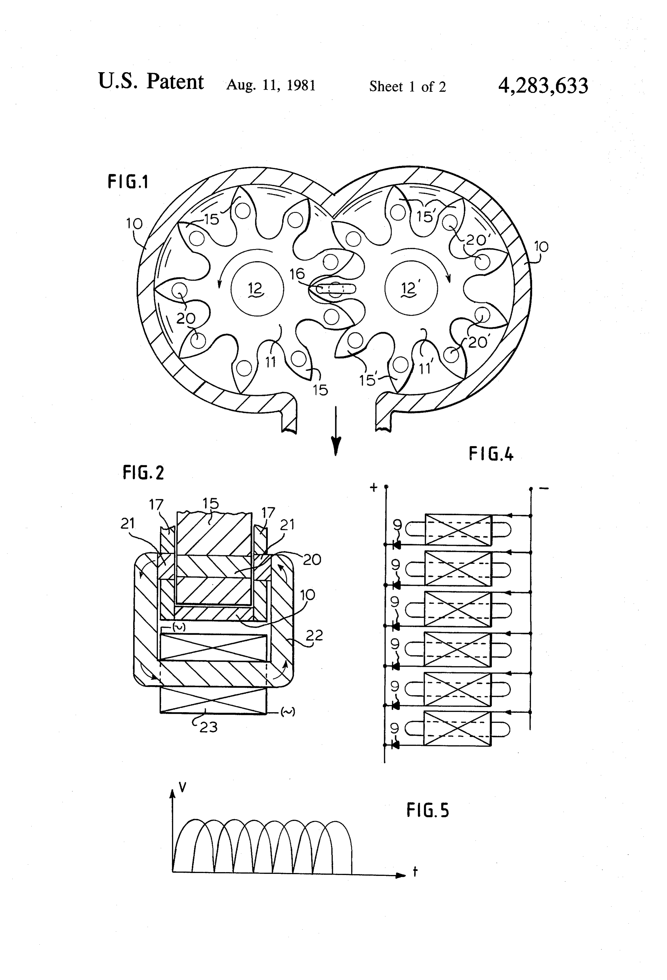
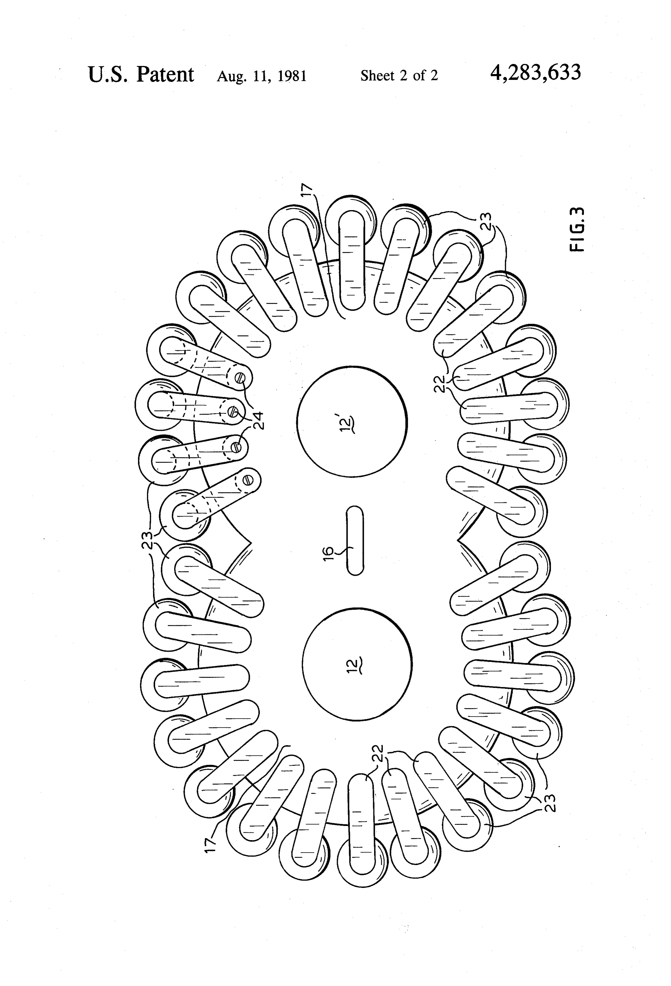
FIG. 5 is a diagram of the voltage vs. time curve of
Page 2drawing sheetscan →
Page 3drawing sheetscan →
Page 4scan →
FIG. 5 is a diagram of the voltage vs. time curve of
ELECTRO-PNEUMATC DYNAMO the emf induced by the multiplicity of rectified dynamo circuits.
The present invention relates to an electropneumatic Turning now in detail to the drawings, FIG. 1 is a dynamo or generator. More particularly, it relates to 5 sectional view of a rotary combustion engine of the type such a dynamo which may be incorporated in an auto disclosed in U.S. Pat. No. 3,323,499, the subject matter mobile to work as an expansion-engine, delivering elec of which is incorporated herein by reference thereto. trical power. The engine mainly consists of an engine casing 10 in In light of the current fuel crisis, the mechanical which two rotors 11, 11" are rotatably supported by transmission loss of a car is a very important factor to 10 means of shafts 12 and 12", respectively, and by bearings consider. The transmission of the delivered power, from (not shown). The rotors 11, 11" rotate in opposite direc the output axle shaft of the motor to the adhesion plane tions and are each provided with a set of rotor blades of the road, involves significant mechanical losses by 15, 15, in this case nine, each set of which is configured friction in all of the interconnected transmission ele to permit meshing engagement thereof with the blades ments. It is generally known that an electric transmis 15 15 of the other set. Although not illustrated, shafts 12, sion has the greatest efficiency and is, moreover, very 12 at the ends thereof, outside of casing 10, are pro adaptable and relatively noiseless.
It is therefore an object of the present invention to vided proper with intermeshing cog-wheels or gears to effect meshing of the sets of blades 15, 15'.
provide an electro-pneumatic dynamo which tends to In operation, gases under pressure are injected eliminate or at least minimize, as much transmission loss through inlet opening 16 provided on both cover plates as possible. 17 of casing 10 (see FIG. 3). This double opening en It is a further object of the present invention to pro vide such a dynamo which is relatively simple in con sures a good penetration of the pressurized gases, thereby resulting in complete filling of the passing struction, economical to fabricate and durable and de pendable in operation. 25 chambers. The pressurized gases are fed into the cham It is a more particular object of the present invention ber defined between the intermeshing set of blades 15, to provide such a dynamo which may be used in an 15'. The mechanical expansion ratio is about 4:1 for automobile to run electric motors coupled to each of the rotors having nine teeth. This causes rotation of rotors 11 and 11" as more fully explained in the aforesaid pa wheels so as to afford four-wheel drive at high speed tent, as the engine is working as an explosion-motor. with the concomittant benefit of achieving significant 30 fuel savings. In accordance with the present invention, casing 10, Certain of the foregoing and related objects are rotors 11 and 11" and cover plates 17 are made of a readily attained in an electro-pneumatic dynamo which strongly non-magnetic material and steel magnets or includes a rotary engine having an engine casing, two iron cylindrical rods 20 are inserted in longitudinal bore rotors rotatably mounted within the casing having in 35 holes of each of the blades 15, 15 at the point of their termeshing blades and fluid medium inlet means for greatest breadth. Alternatively, rods 20 could be elec injecting a fluid medium between two intermeshing tro-magnets fed externally with direct current. For blades of the rotors, with the engine casing and blades instance, rods 20 could comprise electrical conductors being made of a non-magnetic material. The dynamo all of which would be coupled to two contact rings further includes generator means comprising a plurality 40 fixed upon the shafts, with direct current being fed of magnetic rods, each of which is mounted in the top of thereto by the contact brushes. In this case, the desired each of the blades and a plurality of magnetic circuit voltage of the electro-pneumatic dynamo can be regu means mounted on the casing for cooperation with the lated by varying the value of the direct current supplied rods. The circuit means each comprise a coil, a gener and thereby the excitation of the electro-magnets. ally U-shaped magnetic bar having a base on which the 45 As shown in FIG. 2, rods 20 are disposed for succes coil is mounted and two ends between which the rods of sive intermittent registry with paired iron plugs or in one of the rotors passes upon rotation of the rotors so as serts 21 which are mounted in cover plates 17, lying to induce a flow of magnetic flux through the bar and flush with the interior surface thereof but projecting thereby induce a current flow in the coil. slightly beyond the outer surface thereof by a few milli Other objects and features of the present invention 50 meters. Plugs 21 are, in turn, coupled to the opposite will become apparent from the following detailed de ends of a generally U-shaped iron bar 22 so as to define scription when taken in connection with the accompa a generally square-shaped toroidal magnet. A coil 23 is nying drawings which disclose one embodiment of the placed around the base of the bar 22 and the direction of invention. It is to be understood that the drawings are the magnetic flux is shown by the arrows. designed for the purpose of illustration only, and are not 55 Upon rotation of rotors 11, 11", magnetic rods 20 will intended as a definition of the limits of the invention. pass between plugs 21 thereby producing a magnetic in the drawings, wherein similar reference characters current rising from Zero to a maximum value and then denote similar elements throughout the several views: back to zero again, thereby inducing a period of alter FIG. 1 is a fragmentarily-illustrated sectional view of nating current in coil 23.
an engine according to the present invention; 60 If all the magnets 20 in blades 15 are placed with their FIG. 2 is an enlarged, fragmentarily-illustrated verti similar poles on the same side, and if a large number of cal sectional view through one of the rotor blades and the aforementioned circuit element sets are mounted the associated engine casing shown in FIG. 1; upon the engine, as shown in FIG. 3, one can connect FIG.3 is an enlarged, end view of the engine shown all the coils 23 on one side, on a plus-collector-conduc in FIG. 1, further showing the cover plate in position, 65 tor, and on the other side, on a minus-collector-conduc with a multiplicity of the dynamo circuit elements tor (FIG. 4), In every coil 23, there is induced an alter. mounted thereon; nating current, but because of the placed diodes 9, only FIG. 4 is a rectifier circuit diagram; and the positive alternating current pulses can reach the 5 positive collector-conductor; the other half or negative upon the wheels. If one drives these four series-motors pulses of the alternating voltage are not used. with the kinetic energy of the car, they become dyna If the engine is operated, then it shall deliver a direct mos too, and if we spend the developed electrical en current, composed of a very great number of current ergy in a resistance, the whole is a very efficient braking pulses which are equal in amplitude, but differ in time. 5 system for the car.
The electrical current pulses from the left side of the These electrical brakes can be used as a back up to the dynamo (see FIG. 1) are situated between the current conventional drum or disc brakes. They would afford pulses of the right side. Because of the position of the greater driving safety, especially on hills and mountains, blades 15' upon the right rotor 11", with respect to the where grave accidents can frequently occur due to blades 15 of the left rotor 11, the magnetic fluxes pro 10 faulty brakes.
duced an emf following the FIG. 5 curve. Alternatively, the electro-pneumatic dynamo could Because of the fact that more coils are placed on both be driven by a waterfall. However, because water can sides of the dynamo as there are blades 15, 15 upon the not be expanded, a big inlet must be made in the top of rotors 11, 11", all current pulses differ in time. The pro the casing; the output remaining below the engine duced direct current must be flattened by a choke or 15 Works then as a simple cog-wheel-pump, producing smother-coil. electric power.
It should, of course, be realized that by varying the Thus, while only one embodiment of the present number of plugs 21 and their location, the interconnec invention tions of the coils, the direction of the magnets 20 in the course, behas been shown and described, it should, of realized, that many changes and modifica blades 15, 15', etc. many different circuit combinations tions may be made thereunto, without departing from are possible, and the electro-pneumatic dynamo can the spirit and scope of the invention.
also deliver single-phase alternating current, two-phase What is claimed is:
alternating current 180 degrees displaced with respect 1. An electro-pneumatic dynamo comprising: to each other, etc. a casing, two rotors rotatably mounted within said By equipping the electro-pneumatic dynamo with 25 casing having intermeshing blades and inlet means e.g., 30 coils 23, by letting the engine turn at 3,000 rev/- for introducing a fluid between two intermeshing min, and by interconnecting coils 23 as shown in FIG.
4, one obtains: 50X2X 15X9= 13,500 current pulses per blades of said rotors, said casing and blades being second, which together compose the delivered direct made of a non-magnetic material; and Current. 30 generator means including a plurality of magnetic This very great number of current pulses in such a rods, each of which is mounted in the top of each of small unit of time, indicates that only small electro-mag said blades and a plurality of magnetic circuit nets 20 in the blades 15 need be used; otherwise, the means mounted on said casing for cooperation with pneumatic engine would not be strong enough. One said rods, said circuit means each comprising a coil, need not take off more electric energy, as the pneumatic 35 a generally U-shaped magnetic bar having a base motor can deliver mechanical energy. on which said coil is mounted and two ends be The delivered voltages can be chosen as desired by tween which said rods of one of said rotors passes the interconnecting of the coils 23 in series or parallel, upon rotation of said rotors so as to induce a flow and by changing the excitation of the electro-magnets of magnetic flux through said bar and thereby in 20 in the blades. The arrangement of diodes 9 can also 40 ducing a current flow in said coil. be altered, as required. 2. The dynamo according to claim 1, wherein said The electro-pneumatic dynamo can also be driven by generator means additionally includes means for recti compressing air, with steam, with water under pressure, fying the alternating current induced in said coil. with a small waterfall, with the hot water with a certain 3. The dynamo according to claim 1, wherein said interior pressure from a boiler, etc. However, as a first 45 means for rectifying comprises diode circuits or thy immediate application of this new invention, one can ristor circuits, drive the electro-pneumatic dynamo with the output 4. The dynamo according to claim 1, wherein said gases of an explosion- or combustion-motor, while the rods and bars are made from iron.
same provides mechanical power to drive a car, for 5. The dynamo according to claim 1, wherein said example. 50 circuit means includes iron plugs mounted in said cover The output-gases are then much farther exhausted, plates to which the ends of said bars are secured. and the transmission losses strongly reduced, what 6. The dynamo according to claim 1, wherein said surely shall lead to important savings of fuel. inlet means comprise fluid medium inlet means for in Another important result is that the car can be braked jecting a fluid medium.
by electrical means with the present electric motors 55 s
Provenance
- Collection
- Patents citing this work
- Pages
- 5
- Method
- pdftotext (the PDF's own text layer) + pdftoppm 300dpi page scans
- Patent office record
- patents.google.com →
- Source
- Google Patents citing-documents table
- Assignee
- Peter Gijbels
- Published
- 1981-08-11
- Transcribed from
- patentimages.storage.googleapis.com →