

patent · US4286581A
Solar energy conversion system
1 September 1981
Text
Page 1bibliographic recordscan →
United States Patent (19)
Atkinson, Jr.
54 SOLAR ENERGY CONVERSION SYSTEM
75 Inventor: John H. Atkinson, Jr., Laguna
Beach, Calif.
Assignee: Advanced Solar Power Company
(ASPCO), Newport Beach, Calif.
Related U.S. Application Data (63) Continuation-in-part of Ser. No. 665,369, Mar. 10, 1976, abandoned.
51 Int. Cl. ................................................. F24J 3/02 52 U.S. Cl. .................................... 126/439; 126/424;
408,929 8/1889 Reynolds ............................. 126/440 696,326 3/1902 Garza ........ ... 126/440 1,920,094 7/1933 Martin, Jr. . ... 60/641 1,951,403 3/1934 Goddard ................................ 60/641 1,969,839 8/1934 Goddard ... ... 126/439 1,989,999 2/1935 Niederle ... ... 126/443 2,259,902 10/1941 McCain. ... 126/440 2,486,833 1 1/1949 Freund ... ... 26/437 3, 159,554 12/1964 Mount .... ... 26/432 3,203,167 8/1965 Green, Jr. .. ... 126/438 3,234,931 2/1966 Whitaker ... ... 126/438 3,363,618 1/1968 Dominguez .............. ... 126/432
3,901,036 8/1975 Martin .................................. 126/440 4010,614 3/1977 Arthur .... ... 126/439 4,018,212 4/1977 Hein et al. ... 126/45 4,033, 18 7/1977 Powell ................................... 60/64 4,051,835 10/1977 Hinson-Rider ....................... 26/440
FOREIGN PATENT DOCUMENTS
1035833 4/1951 France ..................................... 126/432
OTHER PUBLICATIONS
Kreith, Frank, Principles of Heat Transfer, Scranton,
Pa., International Textbook Co., 1965, pp. 448–453.
Primary Examiner-James C. Yeung
Attorney, Agent, or Firm-Knobbe, Martens, Olson,
Hubbard & Bear
A solar energy collection and conversion system is disclosed in which a cassegrain mirror system is rotated about a diurnal axis, which axis is adjusted for seasonal variations in the incidence of the sun's rays on the earth's surface. A black body absorption cavity filled with translucent or transparent fluid material is used for direct absorption of the sun's rays. The incident solar energy is absorbed directly by the fluid medium. The fluid within the cavity may be maintained under ex tremely high pressures and temperatures in order to utilize this fluid as a heat storage medium. Such heat storage is facilitated by apparatus which permits a change in the volume of the reflective cavity in re sponse to the temperature or pressure of the fluid within the cavity.
59 Claims, 14 Drawing Figures
Drawings
Page 2drawing sheetscan →
Page 3drawing sheetscan →
Page 4drawing sheetscan →
Page 5drawing sheetscan →
Page 6drawing sheetscan →
Page 7drawing sheetscan →
Page 8drawing sheetscan →
Page 9scan →
ing an efficient radiator. Substantial heat is also lost
SOLAR ENERGY CONVERSION SYSTEM through convection to the atmosphere. In addition, such systems, by definition, must operate at relatively
RELATED APPLICATION low temperatures which make the storage of heat ex This is a continuation-in-part of Application Ser. No. 5 tremely perature expensive, since an enormous bulk of low tem storage must be provided. Nonetheless, the 665,369, filed Mar. 10, 1976, abandoned entitled main current thrust of solar energy research an develop
Solar energy conversion system
ment programs is directed toward production of low
BACKGROUND OF THE INVENTION grade power at relatively low temperatures for domes O tic water and space heating. There is also considerable
All of the earth's conventional power sources such as oil, coal, and running water are originally derived from interest in solar powered air conditioning using the the sun. For many years attempts have been made to use Servel process. Extensive commercial use of low grade the heat of the sun directly for power and domestic solar power awaits the development of efficient and needs. Outside the earth's atmosphere, an average 1350 economical collectors so that vast areas are not needed watts per square meter is available. Under good condi 15 to collect sufficient power. The basic technical problem tions, such as a cloudless desert, approximately 1000 is the development of an economical material which watts per square meter is available at the earth's surface. will absorb sunlight with an effective temperature of Solar energy conversion systems described in the 6,000 K. (10,000 F. and not reradiate at a working prior art are generally either so complex as to require 20 temperature of around 350 K. (170 F) to typical sur enormous capital investment, making their utilization roundings at 300 K. (80” F.).
virtually impractical; or are so unsophisticated that In summary large scale utilization of solar energy for their efficiency in absorbing and converting solar en replacing energy presently produced by depleting natu ergy is too low to make their application practical. In ral resources such as fossil fuels has not been practical in the first extreme, there are numerous prior art disclo 25 the past since no system has been produced which com sures of complicated heat storage systems utilizing state bined efficiency and economy, so that both capital ex changes in various salts and other materials, many of pense and operating expenses could be maintained at a which are extremely caustic in one state or the other, sufficiently low level that the solar energy produced and all of which are subject to significant losses through could compete economically with fuel burning systems. the fundamental inefficiency of heat transfer apparatus 30 used for transferring heat absorbed by collection units w
Summary of the invention
to the storage materials. Other costly aspects of compli ss The present invention provides a very significant cated prior art systems include the use of multiple helio stats for redirecting the sun's rays, each of which must advance field, in the solar energy collection and conversion since it permits the manufacture of reasonably be individually controlled in order to track the relative priced collection equipment which operates extremely motion of the sun and the earth's surface, the use of efficiently and incorporates self-contained heat storage critical reflective or refractive surfaces often in shapes capabilities sufficient to overcome the inherent defi and forms which are extremely expensive to mai, fac ciency ture, and through the use of exotic materials which source of at solar energy, that is, the absence of the energy night and on cloudy days.
substantially increase the capital investment required Fundamentally, these advantages are accomplished for the collection of solar energy. Another example of 40 through an efficient, low cost optical system for the the first extreme has been the use of solar power in solar concentration of solar energy and through the direct furnaces. These are very large arrays of optical ele absorption of this ments which concentrate sunlight into a small area system permits the energy by a working fluid. Such a storage of the working fluid itself at producing very high temperatures at the focus. These extremely high temperatures and pressures to provide elements are often unique, very large and expensive 45 installations, with only a few operating worldwide. energy during time periods of total or partial darkness. They are principally used for materials experiments and a The preferred embodiment of this apparatus includes cassegrain optical system incorporating a primary limited production of ceramic and abrasive materials, which cannot be readily produced in any other way. A reflective concave mirror directed toward the sun and typical working temperature for a solar furnace is 50 including a central aperture. Attached to and spaced 3,000 K. This first extreme also includes the direct from this primary mirror is a secondary convex mirror generation of electricity from solar radiation falling on coaxial with the primary mirror and aligned to collect solar cells such as are widely used in the space program. and focus through the aperture of the primary mirror Because each cell can produce only low voltage and solar rays reflected by the primary mirror. current levels, a great number of cells are needed to 55 This entire optical system is rotated about a diurnal produce substantial amounts of electrical energy. Each axis and adjusted for seasonal variations so that the focal cell requires two individual electrical connections and point of the entire optical system is fixed relative the labor costs for millions of connections become prohibi earth's surface.
tive except for critical uses in inaccessible places. There Along the average diurnal axis, that is, the diurnal are also inherent problems in transmitting low voltage 60 axis at equinox, a high pressure vessel in the form of an direct current, and storage of large amounts of power in elongate pipe conducts a transparent or translucent batteries is not presently economical. working fluid. The portion of this pipe adjacent the In the other extreme, most relatively simple or unso focal point of the optical system is provided with a phisticated collectors are flat plate collectors which toroidal lens system which refracts the incident focused expose large flat heat absorbing surfaces of the sun's 65 solar rays along the axis of the pipe. The entire inner rays. These collectors are extremely inefficient in that a surface of the high pressure pipe is highly reflected so substantial portion of the collected energy is reradiated, that rays entering the pipe cavity are reflected to pass the surface which forms an efficient collector also form through the working fluid repeatedly until the radiation 10 energy is totally absorbed by the fluid itself, the reflec is properly ported for the through flow of working tive walls substantially prohibiting absorption of the fluid, no pressure differential occurs across the mirror energy by the pipe itself. The toroidal lens system is so that a relatively simple and preferably remotely actu contained in a highly reflective shutter which rotates so ated driving system may be used for positioning the that only the sun's image falls on the aperture. The mirror. As this mirror is moved away from the toroidal optically closed pipe acts as a black body cavity, rapidly lens, the portion of the high pressure pipe which forms distributing the incident radiation throughout the trans the reflective reservoir is changed in volume, permit parent or translucent medium contained and quickly ting a servo system to maintain the pressure and temper raising this medium to temperature equilibrium. Energy ature of the working fluid within the high pressure pipe cannot be reradiated through the aperture to the much 10 by storing additional thermal energy when the source hotter sun without violating the first law of thermody energy exceeds the demand.
namics. Because energy is absorbed from radiative In a typical installation, a high pressure pump transfer in the bulk of the material contained in the pipe, supplies the working fluid, such as water, to the down the outer walls of the container may be kept cool as, for stream end of the high pressure pipe. This water flows example, by insulation. Since radiative energy transfers 15 through the movable mirror into the reflective cavity occur in accordance with the following formula and directly absorbs energy reflected through it by the AE= o(AT) where AE is the energy transferred, or is cavity walls and the optical system. The water tempera the Stefan-Boltzmaun constant, and AT is the difference ture is raised and the pressure within the vessel is main in absolute temperatures, radiative losses predominate. tained at a level prohibiting vaporization of the water. Thus, maintaining the outside of the container cool 20 The outlet or upstream end of the high pressure pipe is eliminates most losses. The system provides energy connected through a control valve to a turbine, the collection and absorption efficiencies near 90%, which control valve separating the higher pressure and lower is 10 times or more greater than that for a typical solar pressure zones within an outlet pipe and permitting the power system. The maximum temperature available on working fluid to vaporize on the downstream side of the the earth from solar heating is 6,000 K. (10,000 F). 25 valve, the steam thus produced being used to operate a Because of the high efficiency of this system, working turbine. The system may be totally self contained if the temperatures approaching this limit are possible for exhaust steam from the turbine is condensed to provide relatively small amounts of material. The flow of work water supply for the high pressure pump or may be ing fluid through the cavity is adjusted to give the de operated on available water supply with the exhaust sired working temperatures and pressures in that part of 30 steam from the turbine vented to atmosphere. the system. These and other features of the present invention are The optical concentration system may be mounted on best understood through the following detailed descrip the high pressure pipe or separately, but rotates about tion of a preferred embodiment which references the the pipe in accordance with the daily rotation of the drawings, in which:
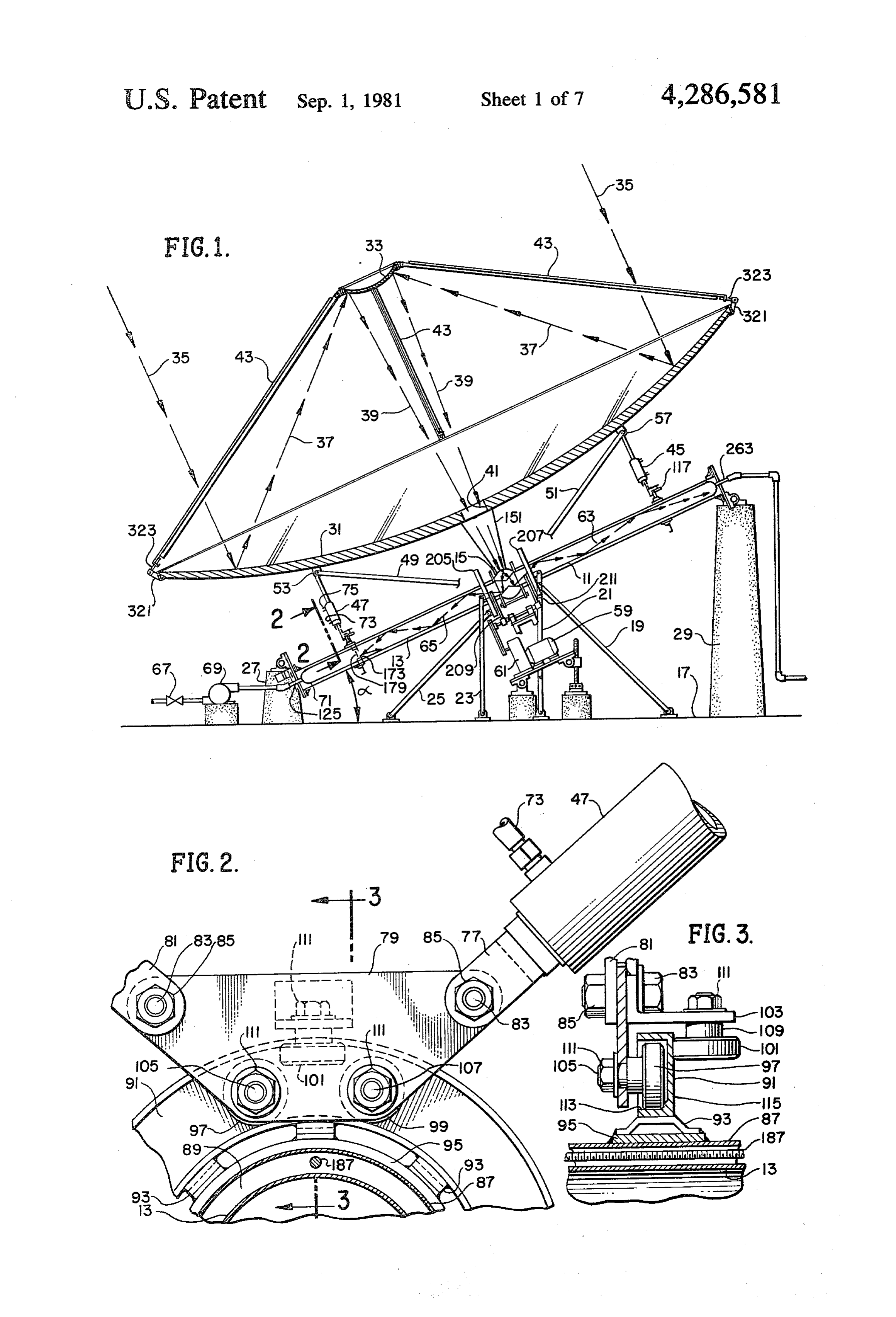
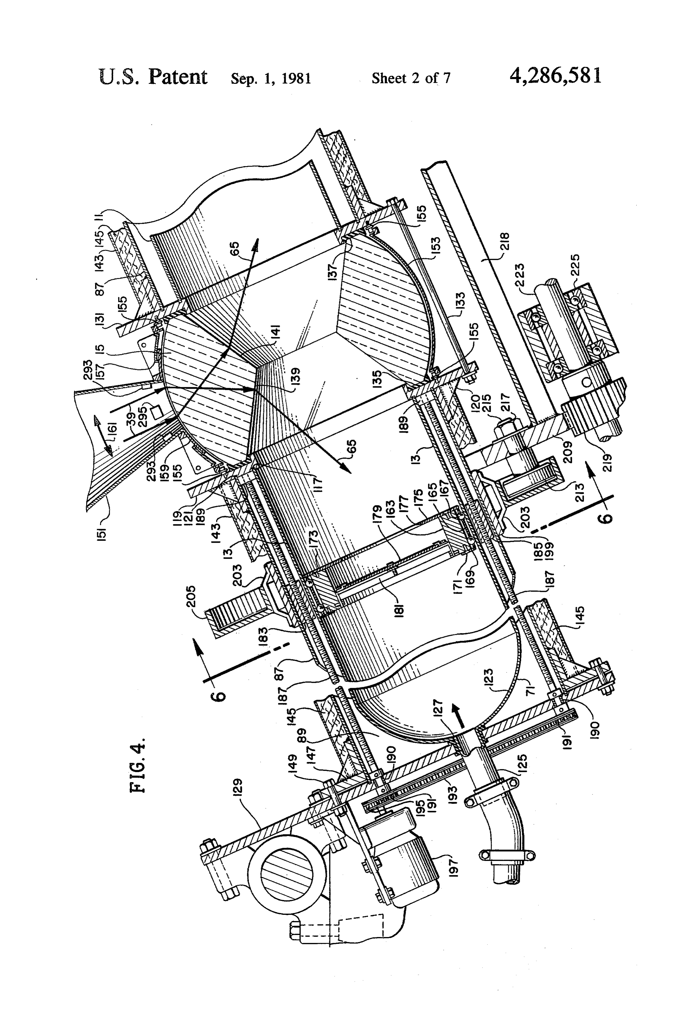
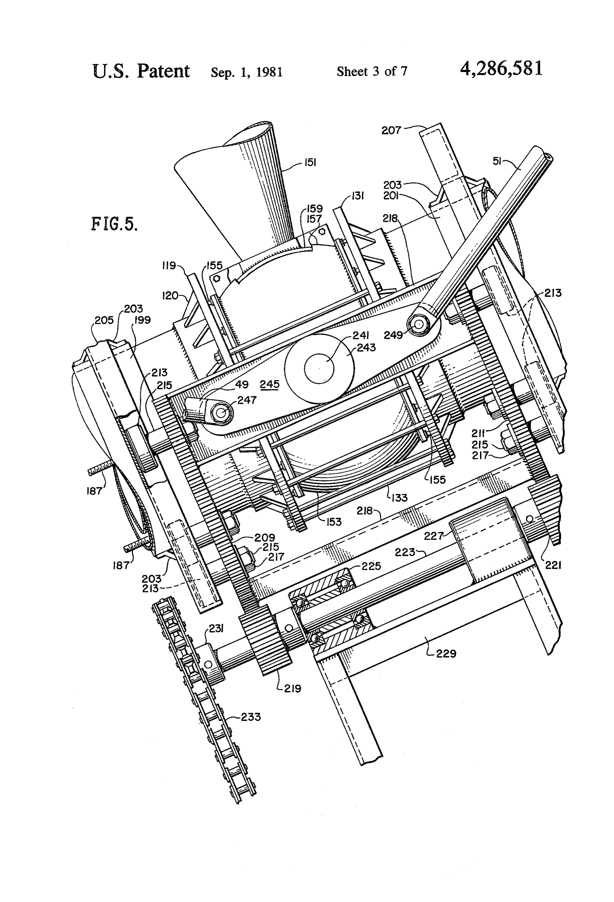
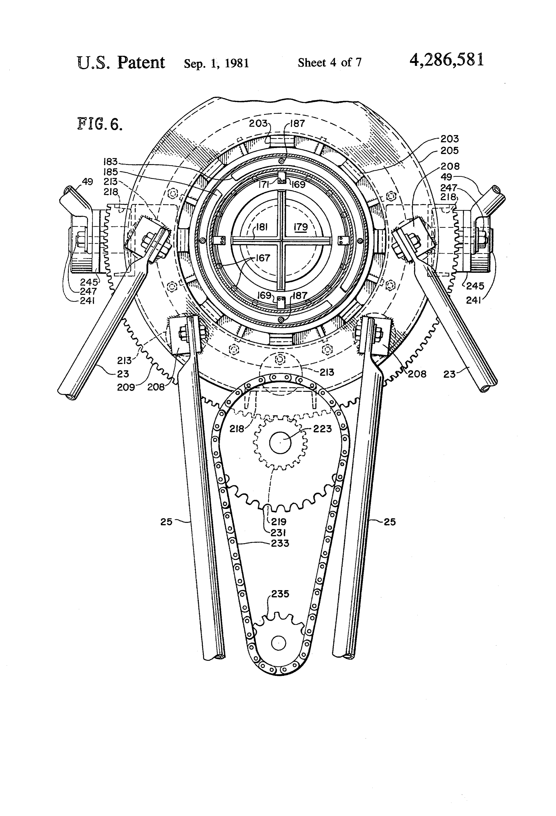
earth to assure that the solar radiation is focused 35 FIG. 1 is a sectional view of the solar collection and through the toroidal lens system. conversion system, the view taken through a plane During periods of substantial incident solar energy, which bisects the high pressure pipe and optical system; when the entire energy capacity of the device is not FIG. 2 is a sectional view showing the mirror support necessary for producing power, the working fluid system taken along lines 2-2 of FIG. 1;
within the high pressure pipe may be heated and pres FIG. 3 is a sectional view further detailing the mirror surized, thus absorbing a large amount of solar energy. support system of FIG. 2 and taken along lines 3-3 of This energy may be removed from the system by per FIG. 2;
mitting flow of the working fluid from the high pressure FIG. 4 is a sectional view of the inlet end and central pipe. Thus, in those instances where water is selected as portion of the high pressure pipe of the system of FIG. the working fluid, a substantial bulk of water may be 45 1 enlarged to show the details thereof; elevated in temperature and sufficiently pressurized so FIG. 5 is an elevation view, partially in section, of the that the water absorbs a large amount of energy. By gearing system located adjacent the focal point of the permitting this heated, pressurized water to escape from optical system of FIG. 1 and used for rotating the opti the high pressure pipe to a lower pressure cavity, the cal system about the high pressure pipe; water will immediately vaporize to produce high pres 50 FIG. 6 is a sectional view taken along lines 6-6 of sure steam which may be used, for example, to run a FIG. 4;
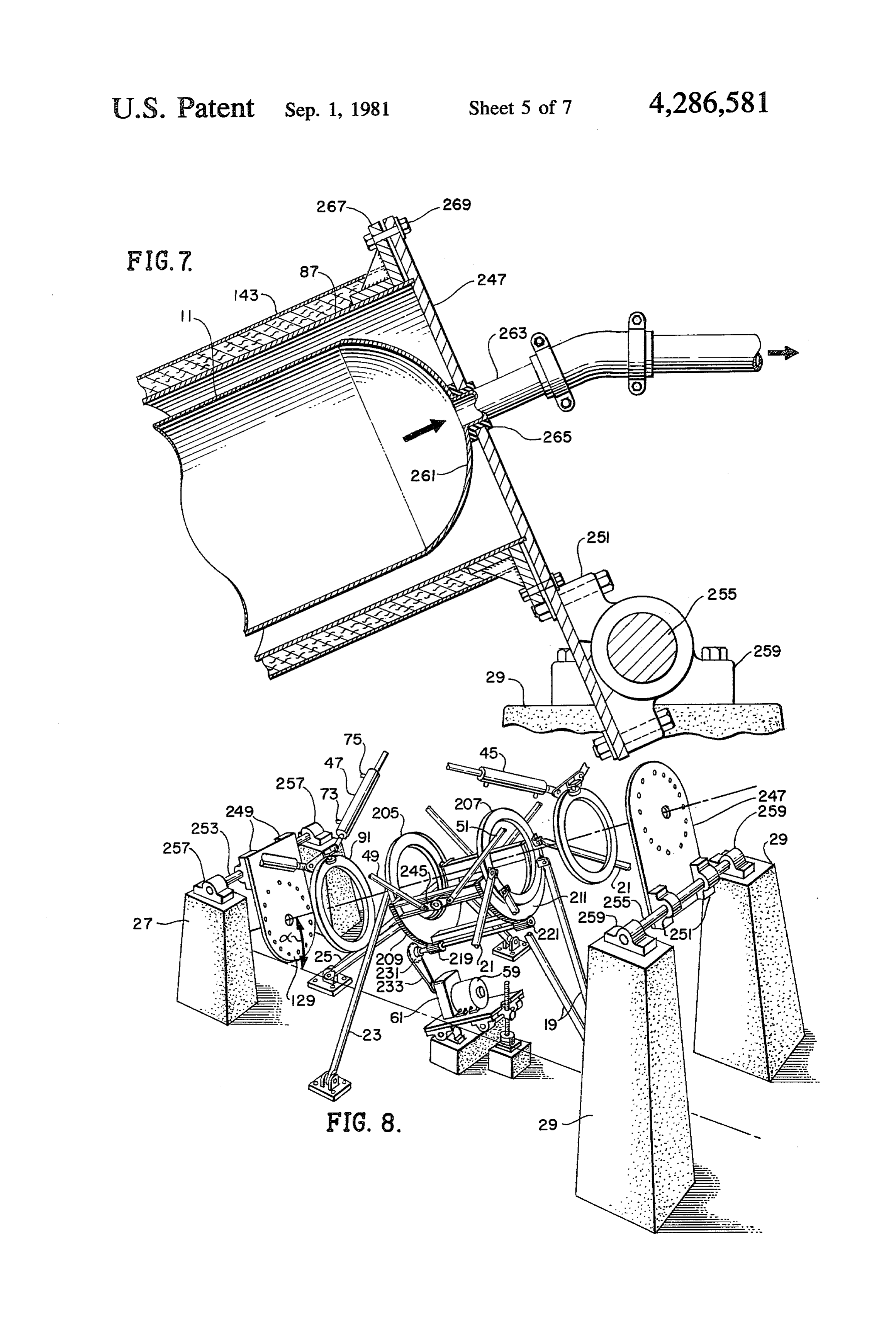
turbine system for generating electricity. FIG. 7 is a sectional view of the outlet end portion of It will be understood that during periods of substan the high pressure pipe of the system of FIG. 1 enlarged tial incident solar energy continuous flow of working to show the details thereof;
fluid to the system may be maintained by a high pres 55 FIG. 8 is a perspective view of the mounting and sure pump, the black body cavity being maintained at rotating apparatus of FIG. 1, with the high pressure very high pressure to prohibit vaporization of the work pipe and optical system removed to facilitate under ing fluid within the cavity. This working fluid is contin standing of the system used for rotating the optical uously removed from the system and permitted to va system about the diurnal axis;
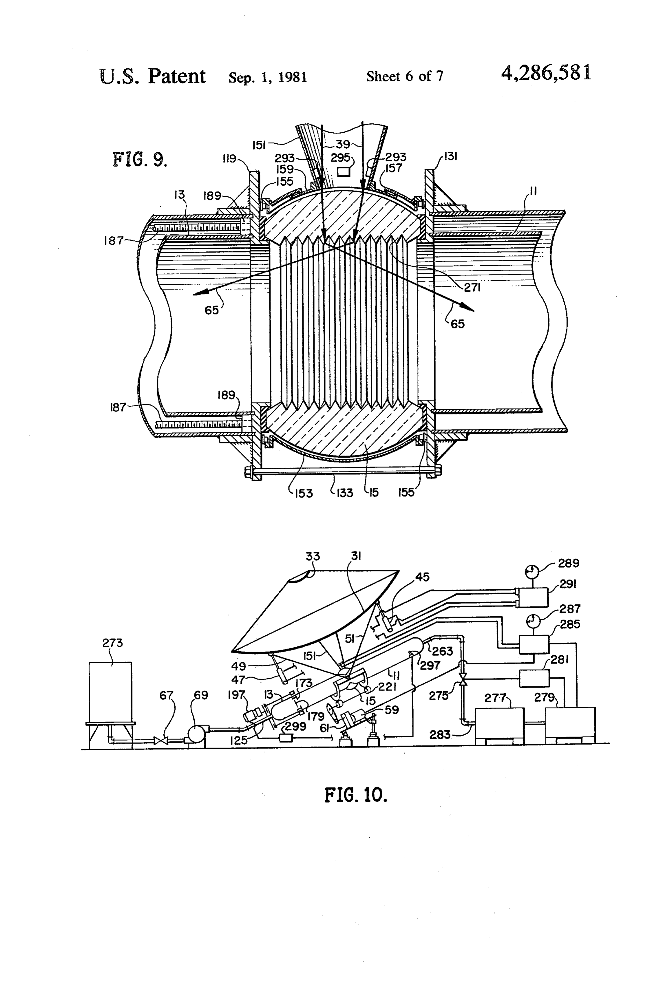
porize for operating, for example, a turbine. At the same 60 FIG. 9 is a sectional view of the central portion of the time the cavity itself may store sufficient working fluid high pressure pipe, enlarged to show the details thereof, to form a substantial energy reserve. similar to the central pipe portion of FIG. 4, but show The reflective cavity formed by the walls of the high ing an alternate embodiment of the toroidal lens struc pressure pipe may be changed in volume during such ture thereof;
use to provide for the storage of different amounts of 65 FIG. 10 is a schematic illustration showing the inter thermal energy. This is accomplished through the use of connection of the solar conversion system of FIG. 1 a mirror positioned within the high pressure pipe and with a steam turbine electrical generating facility for moved along the pipe by a control system. If this mirror producing electrical power;
Page 11scan →
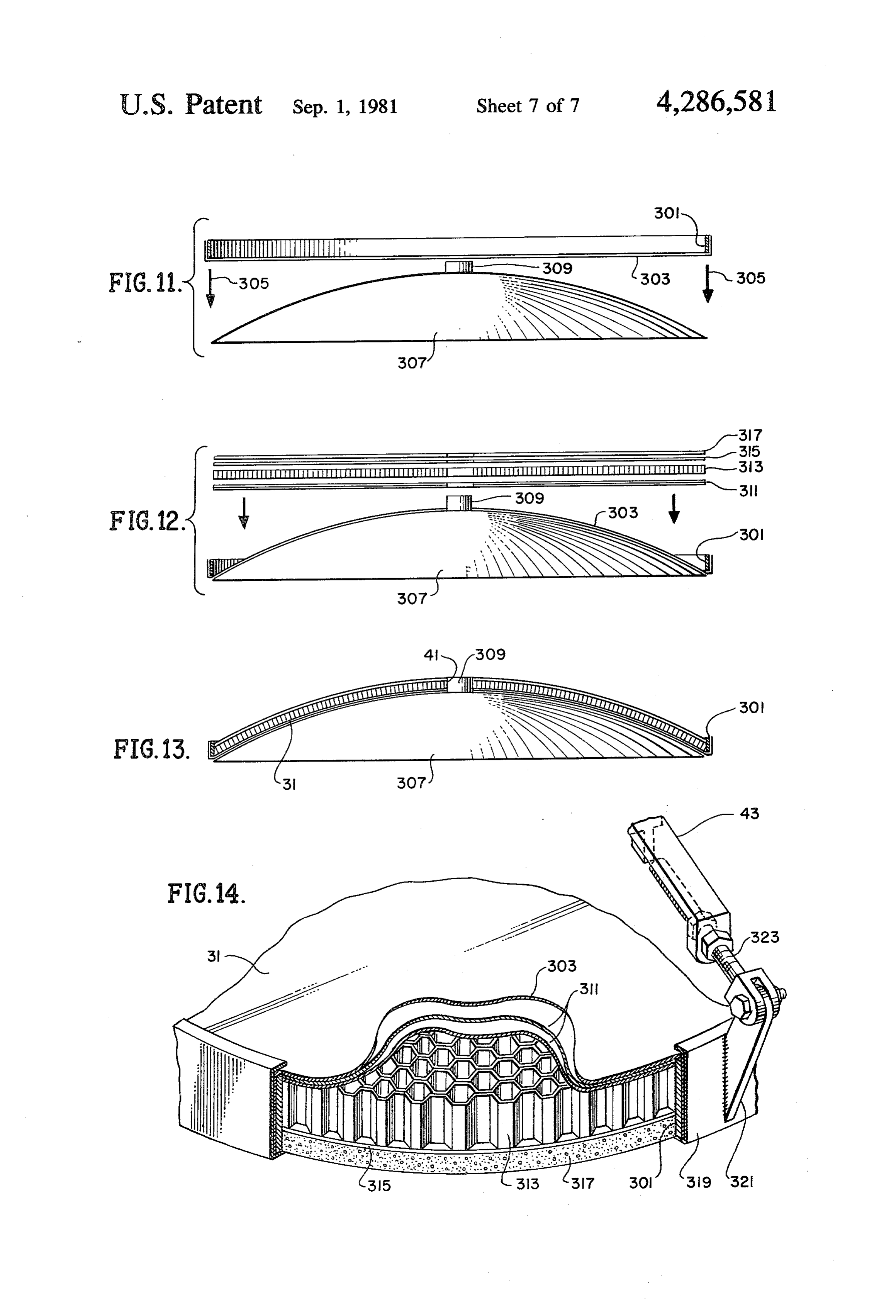
FIGS. 11, 12 and 13 are sectional views of a mold pipes 11 and 13, all incident solar radiation will be fo form and portions of the main reflective mirror of the cused through the toroidal lens 15 at each equinox. optical system of FIG. 1, showing the successive steps In order to adjust for seasonal relative movement of of a method for manufacturing said mirror; and the sun and earth, hydraulic actuators 45 and 47 are FIG. 14 is a perspective view of one edge of the main used to pivot the cassegrain system, including the mir reflective mirror of FIG. 1, partially in section, said rors 31, 33, about a pivotal axis coincident with the toroidal lens 15 and perpendicular to the pipes 11, 13. A view showing the details of construction of said mirror.
pair of struts 49 and 51 are connected at the rotational
DETAILED DESCRIPTION OF THE axis to support flanges 53 and 57, respectively, extend PREFERRED EMBOOIMENT 10 ing from the rear of the primary mirror 31. It will be Referring initially to FIG. 1, the solar collection and recognized from the remaining figures that each of the conversion system of the present invention includes a identical pair and actuators 45 47 of FIG. 1 are duplicated by an of actuators on the opposite side of the high pressure cavity formed, for example, from a pair of high pressure pipes 1, 13, there being four spaced sup high pressure pipes 11 and 13 joined by a toroidal lens 15 port flanges 53, 57 on 15. The high pressure pipes 11, 13 include inside walls In addition, an identicalthepair rear surface of the mirror 31. of struts 49, 51 exist on the which are polished or coated to provide a highly reflec tive interior surface. The pipes 11, 13 are supported other side of the high pressure pipes 11, 13 so that these from a base 17 which may be, for example, a concrete struts 49, 51 and actuators 45, 47 cradle the primary foundation pad, by plural supporting struts 19, 21, 23 20 mirror 31 and support its entire weight. and 25 as well as concrete pylons 27 and 29. Each of the tem 61, to drive
A clock 59, in conjunction with a gearing sys be described in detail below is utilized to struts 19, 21, 23, 25 and concrete pylons 27, 29 illus rotate the cassegrain mirror system about the diurnal trated in FIG. 1 are duplicated by identical supporting axis formed by the pipes 11, 13 on a daily basis, the structures on the opposite side of the high pressure mirrors 31 and 33 rotating through approximately 180" pipes 11, 13, as specifically shown in FIGS. 6 and 8 so 25 during each day and being recycled through the same that the structure is braced against static loads as well as 180° rotation at night to begin another daily diurnal wind forces. The system is arranged such that the pipes rotation on the following dawn. This diurnal rotation of 11 and 13 and their supporting structure are rigidly the mirror system, combined with the seasonal adjust mounted on the foundation 17 and neither move nor ments made by the actuators 45 and 47, assures that the rotate, so that high pressure fittings connecting working 30 rays 39 are always focused at the stationary toroidal lens fluid to and from the pipes 11 and 13 need not include 15. The incident radiation 39 is refracted by the toroidal expensive rotating or articulating couplings. lens 15, in a manner described in more detail below, to An optical collection and focusing system is arranged travel the length of the pipes 11 and 13 as shown at 63 to rotate about a diurnal axis coincident with the sta and 65, respectively. Because of the reflective surface tionary pipes 11, 13. This optical system is a two-mirror 35 on the inside of the high pressure pipes 11, 13, this radia cassegrain system including a primary mirror 31 and tion 63, 65 is repeatedly reflected from the walls of the secondary mirror 33. The primary mirror 31 has a para absorption blackbody cavity formed by the pipes 11, 13 bolic concave surface which is highly reflective for so that, after passing repeatedly through the working collecting and reflecting parallel solar rays 35 toward fluid within the pipes 11, 13, the solar energy is totally the secondary mirror 33, as shown at 37. The secondary absorbed directly by the working fluid. The reflective mirror 33 is a much smaller, convex, paraboloidal mir interior surfaces of the pipes 11, 13 substantially prohib ror which in turn reflects the rays 37 toward a single its absorption of this energy by the pipes themselves. focus, as shown at 39. The rays 39 pass through an Input working fluid, such as water, is supplied through aperture 41 at the center of the primary mirror 31 and a valve 67 and high pressure pump 69 to the inlet end 71 converge on the toroidal lens 15, so that substantially all 45 of the high pressure pipe 13. This working fluid is of the incident radiation 35 is concentrated at the lens heated through direct absorption of the solar energy 15. reflecting throughout the interior volume of the pipes In order to maintain the focus of solar radiation at the 11 and 13, but is preferably not vaporized within the toroidal lens 15, it is necessary to maintain the axis of pipes 11, 13. Rather, the pressure supplied by the pump the primary mirror 31 parallel to the incident radiation 50 69 is sufficient to permitsubstantial heating of the work 35. This is accomplished by mounting the entire optical ing fluid without vaporization. In an exemplary installa system, including the primary mirror 31 and secondary tion wherein the working fluid is water, the pressure mirror 33 which is attached thereto by plural struts 43, and temperature maintained within the high pressure for rotation about a diurnal axis formed by the high pipes 11, 13 is 665 PSI and 500" F. Under these condi pressure pipes 11, 13. The details of this mounting and 55 tions, substantial energy may be stored within the high rotational system will be explained below. pressure pipes 11, 13 themselves. Thus, for example, in The entire solar energy conversion system is this same exemplary system wherein the diameter of the mounted on the foundation 17 such that the high pres primary mirror 31 is 20 meters, the system is designed to sure pipes 11, 13 are parallel to the rotational axis of the produce 300 kw of thermal power. The pipes 11, 13 earth. This is accomplished by mounting the inlet end of 60 have a combined length of approximately 30 meters, a the pipe 13 lower than the outlet end of the pipe 11, so diameter of 20 in., and thus the capacity to store that the angle a is equal to the earth's latitude at the 1.6X 10⁷ BTU of thermal energy. This substantial stor installation location. The concrete pylons 29 are placed age capacity permits the solar energy system to store due north of the concrete pylons 27 in the northern thermal energy during peak solar energy hours and to hemisphere, and due south of the concrete pylons 27 if 65 liberate this energy during hours of total or partial dark the installation is in the southern hemisphere. When ness. It will be noted that, contrary to the storage sys installed in this manner, and with the axis of the casse tems used in the prior art, the storage of energy in the grain mirrors 31 and 33 perpendicular to the axis of the present system is in the working fluid itself, so that no 12 intermediary heat transfer is required. The present sys black body cavity, including variation in shape, as well tem permits an extremely dense storage of energy so as size, of the cavity. A spherical cavity, for example, that the entire system may be installed on site without could not accomodate as large a window as an elongate substantial subsurface storage. In addition, the use of cavity. In general, a window diameter of less than one caustic chemicals for heat storage is avoided, so that 5 tenth or less the maximum linear dimension of the cav both the safety and life expectancy of the system is ity, and preferably no greater than one twentieth the enhanced. maximum cavity linear dimension is required for the From this brief description in reference to FIG. 1, it cavity to perform as a black body. In area terms, the will be recognized that the cavity formed by the high opaque wall area should be at least about seventy times pressure pipes 11, 13 performs, in essence, the function 10 the window area, preferably at least one hundred times of a black body collection cavity. This is accomplished the window area, and, for optimum efficiency, in the by maintaining the energy entrance port defined by the general range of about 200 or more times the diameter toroidal lens structure 15 relatively small in comparison of the window. The overriding criterion, of course, is with the volume of the high pressure pipes 11, 13. The that the cavity be so configured and arranged, in respect difference between this black body absorption system 15 to size, shape and dimension and wall-to-window ratio and those of the prior art, however, is the use of the as to act effectively as a black box absorption cavity for reflective surface on the inside of the cavity defined by incident solar radiant energy.
the high pressure pipes, 11, 13, which forces the solar In this respect, it is recognized that Goddard, U.S. radiation to be directly absorbed by the working me Pat. No. 1,969,839, sought to bring about absorption in dium rather than by an intermediary plate or heat ex 20 a fluid in a chamber. Goddard, however, did not con changer. This direct absorption substantially increases template a black body cavity. Goddard's device is in the efficiency of the system without detracting from the herently limited to comparatively low temperatures black body absorption characteristics of the device. In because, as will be apparent from the placement of the addition, those skilled in the art will recognize the fact window at the largest lateral dimension of the cavity. that, through the use of the toroidal lens structure 15 25 At temperatures where emissivity of the medium is and a shutter to be explained in detail below, any energy significant, there would be extremely large losses which would escape from the system must be directed through the window. The placement of the large win back through the cassegrain mirror system at the sun. dow at the large end of a funnel-shaped chamber, as in Since the effective solar temperature always exceeds Goddard, is antithetical to the present black body cav the temperature within the black body system, no en 30 ity concept.
ergy can be redirected at the sun and the system be In summary, then, the absorbing cavity is so config comes totally absorptive, with the exception of minor ured and arranged as to act, in basic principle, as a black convection losses from the pipes 11 and 13 to the atmo body cavity absorber. The radiant energy which is con sphere, which losses can be effectively controlled centrated and focused into the cavity is retained in the through insulation as described in detail below. The 35 cavity and ultimately absorbed in the fluid in the cavity, overall system thus effectively converts solar energy at either on the first pass through the cavity or on one of an efficiency of approximately 90%, ten times the effi the multiple reflected passes through the cavity, in ei ciency of typical prior art solar collectors. ther case being directly absorbed by the fluid. In the From the foregoing discussion and the exemplary classical black body cavity, absorption occurs primarily embodiment described and depicted in the drawings it at the walls of the cavity. In the present instance, how will be apparent that a central feature of the invention ever, the absorption preferably occurs primarily by the resides in the adaption of the black body cavity princi fluid as the radiant energy traverses the cavity. Any ple in a way not previously contemplated. The classic energy absorbed by the walls, however, immediately is black body cavity, e.g., as conceived by Lummer and conducted to the fluid; hence, at steady state, there is Pringsheim, ideally absorbs all radiation which enters 45 essentially no net absorption of energy by the walls. and radiates none. Of course, there is some radiation in The cavity may be of any shape, but the relationship practice but a hollow body in which the entry window of the cavity size and shape must be such that the cavity is a small fraction of the total interior wall area will act acts as a black body absorber. In general, the effective as an effective black body cavity with negligible or diameter of the window, i.e., the diameter of a circular insubstantial loss. Whether or not a given cavity acts as 50 window which would transmit the same amount of a black body cavity may be determined by known scien radiation as is transmitted by the window in the cavity, tific principles, e.g., by measuring the radiation at the must be a small fraction of the largest linear dimension opening with a given body temperature. Thus, scientifi of the cavity as in classical black body cavities, thereby cally, a black body is an ascertainable structure and it is presenting to the incident radiation essentially all sufficient definition simply to call the cavity of the pres 55 opaque walls, with less than about one percent, and ent invention a black body cavity absorber, thus incor preferably less than about one tenth of one percent, of porating the classical criteria for black body cavity the incident radiation being re-radiated out the window. Structures. Fluid is, in the preferred form, pumped through the In a prototype embodiment of the black body cavity cavity under such conditions as to maintain the fluid at of the present invention, the cavity was a cylindrical 60 liquid density. In low pressure systems, a simple pump is tube four inches in diameter and ten feet long. The all that is required. In high pressure systems wherein window for receiving concentrated solar radiant energy highest efficiency is achieved, the fluid is maintained into the cavity was three inches in diameter. The under high pressure sufficient to keep the fluid at essen opaque wall area of the cavity was approximately 200 tially liquid density, e.g., at the critical point of the times the area of the window and the longest dimension 65 liquid, even though the fluid may behave as a gas when of the cavity was approximately 40 times the diameter allowed to expand. The most effective absorption oc of the window. In practice, of course, considerable curs when the body of fluid in the cavity is at liquid design variation is possible within the criteria for a density. Localized pockets of vapor, and other minor 13 losses, such as heat leakage through the walls, etc., may, channel 91 to maintain the rollers 97 and 99 positioned of course, occur without altering the mode of operation. within the opening of the C-channel 91. It can be seen Water is the preferred fluid, but any other transparent that the support plate 79, along with the actuators 47 or translucent fuid may be used, if temperatures other and the cassegrain mirror system, are thus guided for than conventional steam operating temperatures are 5 rotational movement around the axis of the pipes 11 and desired or if special phase change temperatures, heat 13 for diurnal movement. An identical mounting system capacities, absorption characteristics or other charac 117 (FIG. 1) is used for guiding the actuators 45 for teristics are desired. Heat from the absorption fluid rotary motion about an identical axis. Thus, the pipe 87 may, in a less preferred mode, be extracted by heat is used to support the cassegrain mirror system, includ exchange in the cavity, but this is less efficient than 10 ing the primary mirror 31 and secondary mirror 33, for flowing the fluid through the cavity. rotation about the axis of the pipes 11, 13, guided by the Turning now to the detailed aspects of construction, rail 91.
FIGS. 2 and 3 show a rotating support system used for The actuators 45, 47 may be, for example, hydraulic supporting the actuators 47 on the high pressure pipe actuators which are connected by means of lines 73 and 13. Each actuator 47 is a double-acting hydraulic cylin- 15 75 to a control system which supplies hydraulic fluid to der having first and second hydraulic input lines 73 and tilt the cassegrain mirror system about an axis perpen 75 (FIG. 1). The actuator 47 is mounted by means of a dicular to the pipes 11, 13 and passing through the toroi mounting lug 77 onto a support plate 79. A second dal lens structure 15 to account for seasonal variations mounting lug 81 mounts the second hydraulic actuator in the relative position of the sun and earth. Rotation 47 (not shown), the pair of hydraulic actuators forming 20 about this axis is facilitated by the use of struts 49 and 51 a cradle for one side of the primary mirror 31 and at (FIG. 1) which are connected to a pivot point coinci tached thereto at spaced support flanges 53 (FIG. 1). dent with the toroidal lens 15, as will be described in The mounting lugs 77 and 81 are rigidly clamped to the more detail below, which axis defines the center of support plate 79 by bolts 83 and nuts 85 so that the rotation of the cassegrain mirror structure when the hydraulic cylinders 47 and mounting plate 79 form a 25 actuators 45 and 47 are energized. rigid cradle structure for one side of the primary mirror Referring now to FIG. 4, the detailed construction of 31. An identical support plate and mounting structure is the high pressure pipes 11 and 13, the toroidal lens used for the pair of hydraulic cylinders 45 (FIG. 1) at structure 15 and the surrounding pipe 87 will be ex the other side of the primary mirror 31 to support and plained. The toroidal lens 15 forms, in effect, a bulged cradle that side of the primary mirror 31 at support 30 cylindrical section of fused quartz interconnecting the flanges 57 (FIG. 1) from the high pressure pipe 11, so high pressure pipes 11 and 13. Radiant energy 39 con that the entire weight of the cassegrain mirror system is centrated by the cassegrain mirror system enters one supported from the high pressure pipes 11, 13 at the face of the lens 15 and is refracted, as shown at 65, to support flanges 53 and 57 (FIG. 1) through the hydrau propagate along the length of the high pressure pipes lic actuators 45 and 47. 35 11, 13. This energy, due to the highly reflective inner While the mounting plate 79 bears the weight of the surfaces of the high pressure pipes 11, 13 will be re cassegrain mirror system, it is designed to freely rotate flected repeatedly from the inside walls of the black about the high pressure pipe 13. This high pressure pipe body cavity until it has passed a sufficient distance 13 is surrounded by a coaxial pipe 87 of larger diameter. through the transparent or translucent working medium The pipe 13 defines the walls of the high pressure reflec to be totally absorbed thereby, thus directly heating the tive cavity, while the pipe 87 defines an evacuation working fluid. Since the entire inside of the cavity chamber 89 between the pipes. The chamber 89 is evac formed by the high pressure pipes 11, 13 is reflective, uated, and the inside walls thereof made reflective to the working fluid will achieve a uniform increasing thermally insulate the high pressure pipe 13 from the temperature throughout, the entire cavity being uni outside atmosphere. This insulation is preferably further 45 formly illuminated by the incident collected radiation increased by making the outside walls of pipe 13 reflec and by reradiation from the fluid and walls. tive. Thus both the inner and outer walls of the high The high pressure pipe 13 is open at one end 117 pressure pipes 11, 13, as well as the inner wall of the facing the toroidal lens 15 and is mounted at this open pipe 87 are made reflective, the inner reflective wall of end in an annular mounting plate 119. The mounting the pipes 11, 13 used to form a reflective black body 50 plate 119 may be grooved to receive the open end of the cavity and the remaining reflective walls used for assist pipe 13 and may be welded thereto to insure the pres ing the insulation of that cavity. By evacuating the sure integrity of the vessel. The outer pipe 87 includes a space 89, the high pressure pipes 11 and 13 become, in similar open end 121 which is likewise attached, as by effect, a high pressure dewar for storing energy which welding, to the annular support plate 119. This attach has been converted by the system. 55 ment may be strengthened by plural reinforcing webs The support plate 79 is guided to move in an arcuate 120, which webs 120 also serve to rigidify the mounting path along an arcuate rail 91 which is supported, as by plate 119. The other end 71 of the high pressure pipe 13 brackets 93 and a reinforcing ring 95, to the pipe 87. The is closed, as by a hemispherical end cap 123 welded to arcuate guide rail 91 is formed as a C-channel in which the end of the pipe 13. The hemispherical end cap 123 a pair of rollers 97 and 99 are guided. A third roller 101 includes an opening which is attached to an inlet pipe is mounted to an L-shaped bracket 103 which is at 125 and mounted by means of this inlet pipe 125 and a tached, as by welding, to the support bracket 79. Each vacuum gasket 127 to an end support plate 129. The of the rollers 97,99, 101 is mounted on the support plate remaining open end of the outer pipe 87 is also attached 79 or bracket 103 by a bearing mounted on screws 105, to the end support plate 129 concentric with the pipe 107 and 109, respectively, clamped in place by nuts 111. 65 125. The pipes 13 and 87 are thus concentrically The rollers 97 and 99 bear against the inside surface 113 mounted between the plates 19 and 129 to form a dewar of the lower leg of the arcuate C-channel 91 while the housing for the black body cavity, the space 89 between roller 101 bears against the outer surface 115 of the the pipes being evacuated to insulate the pipe 13.
Page 14scan →
A support plate 131 identical to the support plate 119 Apparatus is included within this system to change is positioned on the other face of the toroidal lens 15, the effective size of the black body cavity bounded by and the pair of support plates 119 and 131 is clamped to reflective surfaces. This apparatus is best understood the lens 15 by a plurality of bolts 133. Annular gaskets through a reference to both FIGS. 4 and 6 and includes 135 and 137 may be used to seal the lens 15 to the plates a cylindrical ferrous member 163, the outer diameter of 119 and 131, these gaskets 135,137 compressed between which is slightly smaller than the inner diameter of the the elements by the bolts 133. This entire structure thus pipe 13. Between these diameters is positioned a ball forms a rigid cavity formed by the pipes 11, 13, plate bearing structure including a bearing spacer ring 165 119, 131 and lens 15, the lens 15 having substantial struc and plural balls 167. The bearing spacer ring 165 is tural strength to resist the extreme pressures within the 10 maintained in position between the ferrous cylinder 163 cavity. and the pipe 13 by a first plurality of positioning plates It will be noted that, in addition to the bulged outer 169 which are attached to the ferrous member 163 by surface of the lens 15, the inner diameter of the lens 15 plural screws 171, and a second annular positioning ring includes a pair of intersecting, coaxial, truncated coni 15 173 which is similarly attached. The ring 173 has a cal surfaces 139 and 141 which form a second refractive highly reflective outer surface 175 and includes a cen surface to assist in refracting the incident radiation to a tral aperture 177 which is smaller than the inside diame path approximately coincident with the axis of the pipes ter of the ferrous cylindrical member 163, the ring 173 11, 13. forming a mirror which extends from a position adja A third relatively lightweight cylindrical enclosure 20 cent the inside diameter of the pipes 13 to the aperture 143 may be used to surround the pipe 87 and to support 177.
therebetween a layer of thermal insulation 145 which A second flat mirror. 179 is mounted, as by a spider reduces the thermal convection losses of the system. member 181 which is attached to the inside diameter of The pipe 87 may be attached to the end plate 129, if the ferrous member 163. The outer diameter of the desired, by an L-shaped annular bracket 147 and plural circular mirror 179 is larger than the diameter of the bolts 149, so that the end plate may be made removable 25 aperture 177 so that the pair of mirrored elements 173 from the system to allow access to the evacuated cavity and 179 form a flat mirrored end for the pipe 13. A 89. space exists between the mirror 179 and the inside diam eter of the ferrous cylindrical member 163 to permit the
As previously explained, the entire cassegrain mirror flow of working fluid around the outside of the mirror system is rotated about an axis coincident with the cen 30 179. Since ter of the lens 15 and perpendicular to the axis of the mirror 179,fluid is allowed to freely flow around the no pressure diferrential exists across this pipes 11, 13 to accommodate seasonal changes in the element and, regardless of the pressure within the pipe relative position of the sun and the earth. As shown in 13, the entire mirror assembly is free to roll on the ball FIGS. 1 and 4, a conical-shaped tube 151 interconnects bearings 167 along the axis of the pipe 13. the opening 41 in the primary mirror 31 to a shutter 35 Movement of this flat mirror assembly is accom system adjacent the toroidal lens 15. This tube 151 is plished by moving a pair of annular permanent magnet used to exclude foreign objects from the area of intense segments 183 and 185, each of which is mounted on and radiation between the aperture 41 and the lens 15. threaded to a pair of threaded rods 187. Each of the The shutter system completely surrounds the outside rods 187 is mounted for rotation in a first end bearing of the toroidal lens 15 and includes a reflective inside surface to eliminate to the greatest extent possible the 189 mounted on the support plate 119 and a second loss of solar radiation through this lens 15. The shutter bearing 190 mounted within apertures within the end is formed as a bulged cylindrical sleeve 153 mounted at support plate 129. The threaded members 187 extend beyond the end plate 129 to support sprockets 191 its open ends on a plurality of rollers 155 so that the which are each engaged by a chain 193. The chain 193 shutter 153 may rotate about the diurnal axis during 45 is additionally engaged by a sprocket 195 attached to daily movement of the lens system about the pipes 11, the rotor of an electrical motor 197. The electrical 13. One side of the shutter 153 includes an opening 157 motor 197 thus serves to rotate each of the four which cooperates with an overlapping flange 159 ex threaded rods 187 in the same direction, these rods in tending from the lower extremity of the conical tube turn threading along the magnet segments 183 and 185 151. As can be seen from FIG. 4, as the cassegrain mir 50 to move the magnet segments along the length of the ror system and its attached tube 151 rotate in the direc pipe 13. The magnetic force between these segments tion indicated by the arrow 161, the flange 159 will 183, 185 and the ferrous element 163 is used to draw the move beneath the opening 157 of the shutter 153 to flat mirror structure along with the moving magnet permit seasonal adjustments, while at the same time sections 183, 185. A rotation of the motor 197 thus maintaining a reflective surface surrounding the lens 15 55 moves the flat mirror partition, including the mirrors over the greatest surface area possible. The inner sur 173 and 179, along the length of the pipe 13 to change face of the shutter 153, as well as the flange 159, are the effective size of the black body cavity 11, 13. Since made highly reflective so that any energy which is only the magnetic force of the magnets 183 and 185 directed toward the shutter system will be reflected. traverses the high pressure pipe 13, the pressure integ Thus, the only aperture for escape of radiant energy is 60 rity of the pipe is not affected through a system of this through the conical tube 151 which, as explained previ type. Numerous alternate methods for moving the mag ously, requires a radiation directly at the solar source, net segments 183, 185, such as linear motors, may be which is impossible. Since the entire shutter system, used, but in each instance the magnets are preferably including the shutter 153, flange 159, and tube 151 are positioned between the pipes 13 and 87 to remotely rotated by movement of the primary mirror 31, the 65 move the flat mirror structure.
shutter rotating on the rollers 155, the aperture 157 With the flat mirror structure, including the mirrors remains directed toward the axis of the cassegrain mir 173 and 179, adjacent the toroidal lens 15, the black ror and system at all times. body cavity in which elevated constant temperatures 15 are maintained by solar radiation is limited to the area and 211 at a rate equivalent to the rate of rotation of the between the flat mirror 173, 197 and the upper end of earth.
the high pressure pipe 11. As will be explained in more An opposing pair of the channel members 218 sup detail below, as the pressure or temperature within the port a pair of coaxial axles 241 extending outwardly black body cavity increases, the storage capacity of the from these channels 218. Mounted, as by bearings 243, system may be adjusted by moving the flat mirror 173, to these axles 241 are a pair of support plates 245, one on 179 toward the inlet 125 of the pipe 13, effectively dou either side of the lens 15, which are in turn rigidly at bling the black body cavity volume when the flat mirror tached to the struts 49 and 51 as through bolts 247 and 173, 179 reaches its other extreme. In operation, the flat 249. It will be appreciated that a pair of struts 49, 51 is mirror 173, 179 is positioned adjacent the toroidal lens O thus attached on either side of the lens 15, and these 15 in the morning, before dawn. When the sun rises struts are, in turn, attached to support flanges 53, 57 above the horizon and heats the working fluid within (FIG. 1) located at spaced locations on the primary the cavity to a predetermined temperature, the motor mirror 31. The axles 241 thus provide a rotational axis 197, under control of a temperature sensor and servo for the entire cassegrain mirror system about the center system, operates to move the flat mirror 173, 177 along 15 of the toroidal lens 15, the movement introduced by the the axis of the pipe 13, enlarging the volume of the solar actuators 45 and 47 (FIG. 1) thus confined to a rotation collection cavity. It will be appreciated that, while no about this axis 241. It will be appreciated that this axis is pressure differential exists across the flat mirror 173, directly supported through the supports 19, 21, 23, 25 179, a substantial thermal gradient exists at this point in from the concrete foundation 17 so that the weight of the system since the fluid upstream of the flat mirror 20 the mirror system is not directly borne at the center of 135, 179 is not subjected to solar radiation and is there the black body cavity formed by the pipes 11 and 13. As fore relatively cool in comparison with the high temper the clock motor 59 drives its sprocket 235, the entire ature fluid within the mirrored walls of the adjustable assembly, including the gear segments 209 and 211, the sized cavity. Some thermal convection may occur channel members 218, and the attached axles 241 rotate through the spaces around the flat mirror 179 to heat 25 in accordance with the diurnal rotation of the earth, the inlet water, but it is assumed that, under normal inducing a rotation through the members 49 and 51 in operating conditions, there is a continuous flow of the cassegrain mirror system, causing this mirror system working fluid through the inlet 125, limiting the con to follow the relative motion of the sun and earth. vection upstream through the spaces around this mirror As best shown in FIGS. 1, 4, 7 and 8, the primary 179, 30 mounting for the solar energy conversation system of Referring now to FIGS. 4, 5, 6 and 8, the mechanism the present invention is preferably accomplished for supporting the struts 49 and 51 of FIG. 1 and for through the end plate 129 attached to the inlet end of controlling diurnal rotation of the cassegrain mirror the system and a similar end plate 247 mounted in identi system will be explained. A pair of reinforcing rings 199 cal fashion, though inverted, to the outlet or upper end and 201 encircle the pipe 87 at locations adjacent the 35 of the high pressure pipe 11, as shown in FIG. 7. These toroidal lens 15. These rings 199, 201 are attached to the end plates 129, 247 are supported on the concrete py pipe 87 through plural circumferentially spaced brack lons 27 and 29, respectively. As previously explained, it ets 203, and are attached to support a pair of facing, has been found advantageous to mount the system so annular C-channels 205 and 207. The C-channels 205 that the axis of the high pressure pipes 11 and 13 is and 207 are, in turn, attached, as through brackets 208 parallel to the earth's axis at the location where the (FIG. 6) to the mounting struts 23 and 25 mentioned in system is installed. In order to facilitate such installa reference to FIG. 1. The mounting struts 23 and 25 thus tion, as particularly shown in FIG. 8, the end plates 129, directly support the C-channels 205 and 207 from the 247 may be attached to pillow blocks 249 and 151, re foundation pad 17 and, through the brackets 203, serve spectively, and thereby rotationally mounted on a pair to support the central portion of the high pressure pipes 45 of axies 253 and 255, respectively. The axles 253 and 255 11, 13 so that undue strain is not placed on the toroidal are, in turn, supported by pairs of pillow blocks 257 and lens 15 by the weight of the cassegrain mirror system. 259, respectively, which are attached to the top of the A pair of hemispherical gear segments 209 and 211 concrete pylons 27 and 29. Through the use of this are supported for movement along the C-channels 205 rotational mounting, the height of the concrete pylons and 207 through plural rollers 213. Each of the rollers 50 27 and 29, as well as their spacing, may be specified by 213 is mounted by a bolt 215 and nut 217 to one of the the manufacturer for a particular site. The concrete gear segments 209, 211 for rotation. The gear segments pylons may then be poured to the desired height so that 209, 211 are interconnected by plural channel members the system may be directly installed thereon by attach 218, attached thereto, as by welding, to form an integral ment of the pillow blocks 257 and 259 to the concrete structure. Thus, the entire structure, including the gear 55 pylon. If the installation is carried out properly, the axis segments 209, 211 and channel members 218 is free to of the cassegrain mirror system, when properly tracking rotate about the axis of the high pressure pipes 11, 13 relative solar movement, will be perpendicular to the through movement of the rollers 213 within the chan axis of the pipes 11, 13 at equinox and will vary there nels 205 and 207. The gear segments 209 and 211 engage from to accommodate seasonal changes through actua with spur gears 219 and 221, respectively, these gears tion of the actuators 45 and 47.
mounted on a common shaft 223 which is rotationally As shown in FIG. 7, the mounting of the upper end of mounted in bearing pillow blocks 225 and 227 from a the high pressure pipe 11 is substantially identical to the stationary support structure 229. The shaft 223 is at mounting of the lower end of the high pressure pipe 13. tached to a sprocket 231 engaged with a chain 233 The high pressure pipe 11 includes a hemispherical end which is driven by a sprocket 235 attached to the rotor 65 cap 261 which is connected to an outlet pipe 263, which of the motor 59 through the gear box 61. The motor 59 outlet pipe 263 is mounted through vacuum gasket 265 is preferably a synchronous, clock-type motor which, to the end plate 247. The outer pipe 87 is connected by through the gear box. 61 drives the gear segments 209 an L-shaped annular flange bracket 267 welded thereon 16 to the end plate 247 by a series of bolts 269, and the an electronic motor control system 285 which may be outer insulation supporting jacket 143 may be mounted connected, for example, to the generator 279 as a source to the bracket 267 as well. of power and which operates in response to signals Referring now to FIG. 9, an alternate embodiment of produced by an electronic clock 287.
the toroidal lens 15 will be described. In this embodi 5 A similar electronic clock 289 and hydraulic control ment, the entire structure is identical to that described in system 291 responsive thereto may be utilized to drive reference to FIG. 4, except that the inner diameter of the actuators 45 and 47 to adjust the relative axes of the the lens 15, rather than including intersecting truncated pipes 11, 13 and cassegrain mirror system 31, 33 for conical refracting surfaces, includes a cylindrical inner seasonal variations in the direction of the earth's axis wall, ruled or grooved to form a Fresnel lens 271. This 10 relative the position of the sun. lens 271 operates in a manner substantially identical to As is well known, the relative movement of the earth the lens structure of FIG. 4, refracting incident radia and sun is extremely predictable and the motor control tion 39 to bend the solar radiation to a direction more 285 and hydraulic control 291 will, in substantially all closely aligned with the axis of the high pressure pipes instances, effectively direct the axis of the cassegrain 11, 13 as shown at 65. It will be recognized by those 15 mirror system 31, 33 to assure that the focused solar skilled in the art that the Fresnel lens of FIG. 9 is the energy will be applied to the aperture in the shutter 153 optical equivalent of the lens structure of FIG. 4. and thus to the black body cavity. As a backup system, Referring now to FIG. 10, a typical overall system however, optical sensors 293 and 295, shown in FIGS. installation utilizing the conversion device of the pres 4 and 9, may be utilized to produce error signals for the ent invention will be described. As previously ex 20 hydraulic actuator 291 and motor control 285, respec plained, solar radiation incident on the primary mirror tively. If the focused solar energy is not centrally lo 31 is reflected from the secondary mirror 33 to enter the cated within the small end of the conical tube 151 used optical cavity defined by the small opening provided in to mount the sensors 293 and 295, an imbalance will the shutter 153 surrounding the lens 15. This solar en occur between oppositely located sensor pair 293 or a ergy is repeatedly reflected from the reflective inner 25 similar oppositely located pair of sensors 295. The op surfaces of the optical cavity defined by the inner walls positely located sensors 293 may thus be used to pro of the pipes 11 and 13 and a movable flat mirror struc duce a differential error signal for the hydraulic actua ture including the mirrors 173 and 179. At all times tor 291, and may override the clock signals 289 to adjust during operation of this system, the entire volume of the for errors produced thereby. Similarly, the sensors 295, pipes 11, 13 is filled with fluid, the density of which is 30 differentially operated, may produce error signals to equal to the liquid density of the working medium. adjust the motor control system 285 in the event of Thus, once the triple point has been exceeded, the fluid error signals from the clock 287. within the optical cavity will have the properties of a The system thus far described is an extremely effi gas, but will nevertheless have the density of liquid cient solar energy conversion apparatus which may be since a sufficiently high pressure is maintained on the 35 mounted at various locations on the surface of the earth system to maintain this density. For the purpose of the through a simple support structure, and which adjusts remainder of this description, the fluid within the black for both diurnal and seasonal variations in the relative body cavity will be referred to, therefore, as a liquid, position of the sun and earth while always maintaining regardless of its temperature. Water is supplied from a the focal point of the cassegrain mirror system 31, 33 at reservoir 273 through a manual control valve 67 and a single location on a stationary cavity 11, 13. The main high pressure pump 69 to the inlet pipe 125 of the pipe tenance of a stationary cavity such as that shown is 13. The pump 69 may be designed to maintain a given extremely beneficial, in that no rotating or moving seals pressure head within the system and this pressure head are required which would increase system expense, will be selected to maintain the density of the working since such seals would be required to withstand the fluid within the system equal to the liquid density of the 45 extreme pressures and temperatures expected in this fluid. Fluid pumped into the system will pass through installation. Thus all diurnal motion of the cassegrain the flat mirror 173, 179 to enter the black body cavity mirror system 31, 33 is about a single axis, permitting and be heated through direct absorption of solar energy. the toroidal lens 15, although located in a stationary The extremely high temperature, high pressure liquid position, to refract all incident energy along the length resulting from this absorption is conducted by means of 50 of the high pressure pipes 11, 13. In addition, the use of the outlet pipe 263 through an automatically controlled direct absorption of this solar energy by the transparent valve 275 to a steam turbine 277 used to drive, for exam or translucent fluid medium itself is extremely efficient, ple, an electrical generator 279. The rotational rate of no intermediary absorption plate or heat exchangers the turbine 277 and generator 279 may be controlled, being required for the absorption of energy. By main for example, by an electronic control system 281 used to 55 taining the optical aperture extremely small, no energy regulate the valve 275. It will be understood that a is permitted to reradiate from the system, since such pressure differential exists across the valve 275, such radiation would require a radiation back toward the sun that a much lower pressure exists at the inlet 283 of the which would violate the first law of thermodynamics. turbine 277 than within the black body cavity, so that Furthermore, by maintaining convection losses at a the liquid immediately vaporizes to produce a high 60 minimum through a dewar-type construction and other volume, high pressure vapor source for driving the insulating techniques, the energy absorption efficiency turbine 277. It will likewise be recognized that the ex of this system may be maintained at an extremely high haust steam or other gas from the turbine 277 may be level. In addition, the system operates as a means of exhausted to atmosphere or may be condensed to sup storing the energy thus absorbed, both efficiently and ply water to the reservoir 273. 65 without the use of heat exchangers or dangerous materi The clockwork motor 59, which through the gear als, the inventor having found that the high pressure, box. 61 drives the cassegrain mirror system about the high temperature working fluid itself may be utilized to diurnal axis on a daily basis, is typically energized from store large amounts of energy for use during periods of 17 total or partial darkness. Since the movable flat mirror place in this configuration, resulting in an extremely 173, 179 effectively varies the size of the black body rigid, very lightweight structure. Each of the layers 311 cavity to control the temperature within the cavity, the through 317 may be apertured to receive the cylindrical cavity size may be made larger when high levels of solar extension 309, thus forming the central aperture 41 for energy are available. In this respect, FIG. 10 shows a 5 the primary mirror 31.
temperature sensing probe 297 connected to a motor FIG. 14 shows a perspective view, partially cut control system 299 used to drive the motor 197 for away, of the primary mirror 31 with the reflective sur adjusting the position of the flat mirrors 173 and 179. In face uppermost in this figure. This structure includes an the morning, when the bulk of the stored energy within aluminum and mylar layer 303, the mylar layer being the pipes 11, 13 has been utilized, the temperature 0 uppermost, and epoxy layer 311 attached to the alumi within the vessel will be relatively low and the motor nun of the layer 303 as well as the cardboard honey control system 299, in response to the temperature sen comb layer 313, a second epoxy layer 315 and the low sor 297, will have adjusted the flat mirrors 173, 179 to a density foam layer 317. It will be appreciated that each position adjacent the toroidal lens 15. During the day, layer is bonded to the next, forming a lightweight sand as solar energy is absorbed, if more solar energy is ab 15 wich structure having extremely high compression sorbed into the fluid within the black body cavity than strength. This assembly is surrounded by the original is required for maintaining operation of the turbine 277 epoxy-impregnated cardboard ring 301 which is bonded and generator 279, the temperature sensed by the probe to each of the layers, and this ring 301 may, in turn, be 297 will increase, causing the motor control system 299 surrounded by and bonded to a protective metal ring to move the flat mirrors 173, 179 upstream toward the 20 319. The ring 319 may be used, through an extension inlet 125 of the pipe 13, increasing the effective size of bracket 321, to mount the struts 43 used to support the the black body cavity and permitting the storage of this secondary mirror 31 (FIG. 1). These struts 43 may be additional available energy. made adjustable in length through the use of a turn As is recognized by those skilled in the art, the manu buckle connection 323, as shown in FIG. 14, permitting facture of a large primary mirror 31 which may be 25 the axes of the mirrors 31 and 33 to be accurately mounted and rotated using systems such as those shown aligned during installation of the system. has not heretofore been possible. The present invention The sun subtends approximately 30 arc minutes at the therefore includes novel techniques and materials for earth and the optical system as described herein is capa the manufacture of the primary mirror 31 to provide an ble of approximately one arc minute of optical quality, extremely rigid, lightweight structure of sufficient opti 30 which will permit a collection of over 90% of the sun's cal quality to focus the solar radiation through the toroi energy falling on its aperture. At the same time, the dal lens 15. This is accomplished using the method out primary mirror 31 is relatively inexpensive to manufac lined in FIGS. 11, 12 and 13. Initially, a large ring 301 ture and may be manufactured in extremely large sizes. may be fabricated by using, for example, corrugated As an example, the primary mirror 31 of the preferred cardboard material impregnated with epoxy to make it 35 embodiment may be 20 meters in diameter while still rigid. A sheet of aluminized MYLAR 303 is stretched providing sufficient rigidity to maintain the required across one face of the ring 301 and attached thereto, as optical quality, all without excessive weight which by epoxy. This sheet 303, as viewed in FIG. 11, has an would interfere with rotation of the system as required aluminum layer on the top and a MYLAR layer for by the relative motion of the sun and earth. strength and corrosion resistance on the underside. This 40 The combination of this unique mirror system with material is presently available in mirror-like highly flex the direct solar absorption apparatus described in refer ible, highly reflective sheets. This assembly of the ring ence to FIGS. 1 through 10 permits a relatively low 301 and stretched sheet 303 is pressed, as shown by the cost, extremely efficient energy absorption and storage arrows 305, over a large male mold 307 formed as a system which may be effectively mass produced, paraboloid and defining the curvature of the primary 45 shipped and installed in various locations to supply mirror 31. A cylinder 309 may extend from the central electrical and thermal energy requirements to replace axis of the male mold 307 to provide the aperture 41 for the utilization of fossil fuels. The high efficiency and the completed mirror, and the sheet 303 may be cut to energy storage of the present system makes it far more pass over the cylindrical form 309. practical than prior art solar energy conversion systems When the ring 301 and its attached sheet 303 are 50 which have been developed and provides an extremely pressed down over the male mold 307, as shown in FIG. practical energy source.
12, the resilience of the sheet 303 will make this sheet In addition to other changes to the specific structure conform precisely to the contours of the male mold 307. disclosed which will be apparent to those skilled in the The ring 301 is held depressed, and a layer of epoxy and art and which permit the practice of this invention glass 311 is applied to the aluminum backing of the 55 while deviating only from the details, those skilled in aluminized mylar sheet 301. Cardboard honeycomb the art will realize also that the interior surface of the material 313, with honeycomb axes vertical as viewed pipes 11, 13 need not be reflective. So long as the energy in FIG. 12, is then placed over the epoxy and glass layer is transmitted directly to the interior of the pipes 11, 13, 311 to conform with the shape of the male mold 311, even highly absorptive walls will immediately attain the and the cardboard 313 is coated with epoxy to lend 60 same temperature as the included fluid such that they rigidity. A backing layer of epoxy and glass 315 is then will reradiate as much energy as they absorb, the net applied to seal the open ends of the cardboard honey effect being that the working fluid directly absorbs comb material 313, and may be epoxied thereto. A final radiated energy rather than being heated by convection layer of low density foam material 317 is then attached from the container walls.
to the epoxy material 315 to complete the assembly. 65 I claim:
This completed assembly is shown in FIG. 13. Each of 1. Apparatus for converting radiant solar energy, the layers 311 through 327 are placed on the sheet 303 comprising:
to conform with the male mold 307 and are epoxied in means for focusing said radiant energy; and 18 opaque optically closed black body cavity means 9. Apparatus for converting radiant solar energy containing a transparent or translucent medium comprising:
and a transparent window positioned near the focal means for focusing said radiant energy; and point of said focusing means, the area of said win an optically closed black body cavity containing a dow which admits solar energy to said cavity 5 transparent or translucent medium, wherein said means being less than one percent of the wall area medium is water, and wherein said cavity forms a of said cavity means, said medium directly absorb high pressure vessel for withstanding pressures ing substantially all of said focused radiant energy required for prohibiting vaporization of said water, entering said closed cavity means through said and a transparent window positioned near the focal window, said cavity including means for repeat 10 point of said focusing means, said water directly edly reflecting said radiant energy from the walls absorbing said focused radiant energy entering said of said cavity to provide repeated transmission of closed vessel through said window, said cavity said radiant energy through said medium. including means for repeatedly reflecting said radi 2. Apparatus for converting solar energy as defined in ant energy from the walls of said cavity to provide claim 1 wherein said cavity means comprises: 15 repeated transmission of said radiant energy a vessel having reflective inside walls and wherein through said water.
said transparent window is sealed in said aperture 1ng: 10. Apparatus for converting solar energy, compris for admitting said focused energy to said vessel.
3. Apparatus for converting solar energy as defined in a black body cavity vessel containing a fluid and claim 1 wherein said cavity means is stationary, said 20 having means for repeatedly reflecting solar en apparatus, additionally comprising: ergy from the walls of said cavity; means for adjusting the position of said focusing means utilizing the solar energy incident on an area of means to provide a focus for said energy which predetermined size for heating said fluid within remains on said window as the relative position of 25 said vessel; and the earth and sun changes. means permeable to said fluid for adjusting the vol ume of said vessel.
4. Apparatus for converting solar energy as defined in 11. Apparatus for converting solar energy as defined claim 1, additionally comprising: in claim 10 wherein said adjusting means automatically means connected to said cavity means for pumping adjusts said volume in response to the temperature of said fluid through said cavity means. 30 said fluid.
5. Apparatus for converting solar energy as defined in 12. Apparatus for converting solar energy as defined claim 1 wherein said focusing means comprises: in claim 11 wherein said adjusting means automatically a cassegrain mirror system.
6. Apparatus for converting solar energy as defined in maintains said temperature constant.
Apparatus for converting solar energy as defined claim 1, additionally comprising: 35 in claim 10 wherein the inside walls of said vessel are a container surrounding and spaced from said cavity reflective and wherein said adjusting means comprises: means, the space between said container and said a reflective partition mounted within said vessel and cavity means being evacuated. movable relative thereto. . 7. Apparatus for converting radiant solar energy, 14. Apparatus for converting solar energy as defined comprising: in claim 13 wherein said adjusting means additionally means for focusing said radiant energy; comprises:
an optically closed black body cavity containing a means for automatically moving said reflective parti transparent or translucent medium and a transpar tion relative said vessel in response to the tempera ent window positioned near the focal point of said ture of said fluid.
focusing means, said medium directly absorbing 45 15. Apparatus for converting solar energy as defined said focused radiant energy entering said closed in claim 10 wherein said heating means comprises means vessel through said window, said cavity including focusing said solar energy incident on an area of prede means for repeatedly reflecting said radiant energy termined size.
from the walls of said cavity to provide repeated 16. Apparatus for converting solar energy as defined transmission of said radiant energy through said 50 in claim 15 wherein said vessel includes an aperture medium; and located at the focus of said focusing means. means for adjusting the volume of said optically 17. Apparatus for converting solar energy as defined closed cavity. in claim 16 wherein said vessel is designed to withstand 8. Apparatus for converting radiant solar energy high pressures of said fluid and wherein said aperture is comprising: 55 covered by a transparent, pressure resistant element. means for focusing said radiant energy; 18. Apparatus for converting solar energy as defined an optically closed black body cavity containing a in claim 10 wherein said heating means heats said fluid transparent or translucent fluid medium, and a through direct absorption of said solar energy by said. transparent window positioned near the focal point fluid.
of said focusing means, said fluid directly absorbing 60 19. A method of converting solar energy comprising: said focused radiant energy entering said closed supplying and withdrawing a working liquid medium vessel through said window, said cavity including to and from an opaque, optically closed black body means for repeatedly reflecting said radiant energy cavity;
from the walls of said cavity to provide repeated focusing solar energy within said cavity through a transmission of said radiant energy through said 65 window having an area which is less than one per fluid; and cent of the area of said cavity; and means for pressurizing said fluid within said cavity to directly absorbing substantially all of said focused prohibit vaporization thereof. energy in said working liquid medium through 19 repeated reflection of said energy from the walls of means utilizing solar energy for storing substantial said cavity and repeated transmission of said en energy in said liquid by radiatively heating said ergy through said working liquid medium. liquid, said vessel including means for repeatedly 20. A method of converting solar energy as defined in reflecting said radiant energy from the walls of said claim 19 wherein said focusing step comprises: cavity, to a temperature above the atmospheric reflecting said solar energy from a primary concave pressure boiling point thereof to pressurize said mirror having a central aperture; liquid, said vessel confining said liquid during heat reflecting said solar energy previously reflected by ing to maintain the density thereof substantially said primary mirror from a secondary convex mir equal to that of its liquid state; and ror toward a focal point through said aperture. O means for withdrawing said liquid from said vessel 21. A method of converting solar energy as defined in and lowering the pressure thereon to vaporize said claim 20, additionally comprising: liquid and produce physical work in response to adjusting the positions of said primary and secondary the pressurized vapor so produced. mirrors to track the relative movement of the sun 29. Apparatus for converting and storing solar energy and earth while maintaining said focal point at a 15 as defined in claim 28 wherein said heating means heats fixed location. said liquid by direct absorption of solar energy by said 22. A method of converting solar energy comprising: liquid.
supplying and withdrawing a liquid to and from an 30. Apparatus for converting and storing solar energy optically closed black body cavity, wherein said as defined in claim 29 wherein said vessel includes an supplying step comprises: 20 aperture sealed by a transparent cover for admitting pumping said liquid into said cavity at a pressure solar energy to said vessel.
which maintains said liquid at liquid density, 31. Apparatus for converting and storing solar energy when said cavity is at a temperature above the as defined in claim 30 wherein the interior walls of said atmospheric pressure boiling point of said liquid; vessel are highly reflective to facilitate said direct ab focusing solar energy within said cavity; and 25 directly absorbing said focused energy in said sorption 32.
of solar energy.
Apparatus for converting and storing solar energy working medium by repeatedly reflecting said as defined in claim 28 wherein said heating means heats solar energy from the walls of said cavity.
23. A method of converting solar energy comprising: only a portion of the volume of said fluid within said supplying and withdrawing a working medium, said 30 vessel, means said apparatus additionally comprising:
for adjusting the volume of said fluid heated by medium being a fluid, to and from an optically said heating means.
closed black body cavity; 33. Apparatus for converting and storing solar energy focusing solar energy within said cavity; as defined in claim 28 wherein said heating means com adjusting the volume of said working fluid directly prises:
absorbing said focused energy; and 35 a cassegrain mirror system for focusing solar energy;
directly absorbing said focused energy in said work and ing fluid by repeatedly reflecting said solar energy means for rotating said cassegrain mirror system diur from the walls of said cavity. nally about its own focus.
24. A method of converting solar energy comprising: 34. Apparatus for converting and storing solar energy supplying fluid under pressure to a black body cavity as defined in claim 33 additionally comprising: vessel; means for rotating said cassegrain mirror system heating said fluid within said vessel by concentrating about its own focus to adjust for seasonal changes the solar energy incident on a predetermined area in the relative positions of the sun and earth. and focusing said concentrated energy into said 35. A method of converting and storing solar energy, vessel and repeatedly reflecting said energy from 45 the walls of said vessel for direct absorption by said comprising:
radiatively heating a liquid with solar energy within a fluid within said vessel; and black body cavity which includes means for repeat adjusting the volume of said vessel to adjust the vol edly reflecting said energy from the walls of said ume of fluid directly absorbing said energy within cavity to a temperature exceeding the atmospheric
25. A method of converting solar energy as defined in pressure boiling point thereof; claim 24 wherein said adjusting step comprises: confining said liquid during heating to maintain the adjusting the position of a reflective partition within density thereof substantially equal to the liquid said vessel. density thereof to store energy therein; and 26. A method of converting solar energy as defined in 55 loweringliquid the pressure on said liquid to vaporize said and thereby produce large quantities of claim 24 wherein said adjusting step comprises:
monitoring the temperature of said fluid; and heated vapor.
automatically adjusting said volume in response to 36. A method of converting and storing solar energy said temperature. as defined in claim 35 wherein said heating step com 27. A method of converting solar energy as defined in 60 prises:
claim 24 wherein said adjusting step occurs automati directly absorbing said solar energy within said liq cally to maintain a constant temperature within said uid.
vessel. 37. A method of converting and storing Solar energy 28. Apparatus for converting and storing solar en as defined in claim 35, additionally comprising: ergy, comprising: 65 adjusting the volume of said confined liquid heated a black body cavity vessel constructed to withstand by said solar energy.
high internal pressures; 38. A method of converting and storing solar energy a liquid filling said vessel; as defined in claim 37, additionally comprising:
Page 20scan →
reflecting said solar energy repeatedly through said apertured primary mirror of said cassegrain mirror sys liquid. tem comprises:
39. Apparatus for collecting, uconcentrating and con a reflective concave surface element; and verting solar energy, comprising: a honeycomb structure bonded to said concave sur a high pressure, opaque black body cavity mounted in 5 face element, the axes of said honeycomb structure a stationary position, said cavity having an aper being substantially perpendicular to said concave ture, the wall area of said cavity being reflective surface. - and being at least 100 times the area of said aper 46. Apparatus for collecting, concentrating and con ture, said cavity having an inlet and an outlet and verting solar energy as defined in claim 45 wherein said filled during use with a transparent or translucent O honeycomb structure is formed of cardboard. working fluid; 47. Apparatus for collecting, concentrating and con a transparent, pressure resistant window covering verting solar energy as defined in claim 46 wherein said said aperture; transparent, pressure resistant window comprises: a high pressure pump for supplying said working a lens for refracting said solar energy focused by said fluid at high pressure to said cavity inlet; 15 cassegrain mirror system into said cavity. means for converting said high pressure working 48. Apparatus for collecting, concentrating and con fluid when heated, to mechanical energy, said con verting solar energy as defined in claim 47 wherein said verting means connected to said cavity outlet; cavity is cylindrical in shape, said cavity aperture com means for concentrating solar energy incident on a prises a circumferential slot in said cavity, and said lens fixed area and focusing said energy through said 20 comprises:
aperture and window into said fluid within said a toroidal quartz element conforming to said circum opaque cavity for direct absorption by said fluid; ferential slot, said element bulged beyond the cylin and drical outer diameter of said cavity. means for adjusting the position of said concentrating 49. Apparatus for collecting, concentrating and con means to maintain the focus thereof at a fixed posi 25 verting solar energy as defined in claim 48 wherein said tion coincident with said window while tracking toroidal quartz element includes a Fresnel lens on its the relative motion of the earth and sun. inner surface.
40. Apparatus for collecting, concentrating and con 50. Apparatus for converting radiant solar energy, verting solar energy as defined in claim 39 additionally comprising:
comprising: 30 closed, opaque, black body cavity means for storing a a mirror mounted within said cavity, said mirror transparent or translucent medium, said cavity apertured to permit said working fluid to flow means having an opening, the area of which is less therethrough, said mirror mounted between said than one percent of the wall area of the cavity inlet and outlet and separating said cavity into two means, said cavity means including means for re subcavities, said mirror limiting said direct absorp 35 peatedly reflecting solar energy; and tion of solar energy to the working fluid in only means for focusing solar radiant energy into said one of said subcavities. cavity means through said opening for direct ab 41. Apparatus for collecting, concentrating and con sorption of substantially all of said energy through verting solar energy as defined in claim 40 additionally repeated re-transmission through said medium in comprising: the volume of said medium. means for adjusting the position of said mirror within 51. A method for converting radiant solar energy, said cavity to alter the volume of said one of said comprising:
subcavities. concentrating radiant solar energy, and focusing said 42. Apparatus for collecting, concentrating and con energy into an opaque black body cavity contain verting solar energy as defined in claim 41 wherein said 45 ing a fluid to be heated by said solar energy mirror position adjustment means comprises: through a window; and a first magnetic element mounted on said mirror; directly absorbing substantial all solar radiation enter a second magnetic element, mounted outside said ing said cavity through said window to heat said cavity, said second magnetic element attracting fluid within said cavity means by repeatedly re said first magnetic element to induce motion 50 flecting solar energy from the walls of said cavity therein; and while maintaining the temperature within said fluid a linear actuator for moving said second magnetic uniform, while maintaining the entire mass of said element along the outer surface of said cavity. fluid at or above the temperature of the walls of 43. Apparatus for collecting, concentrating and con said cavity.
verting solar energy as defined in claim 42, additionally 55 52. Apparatus for converting radiant solar energy, comprising: comprising:
a double-walled vessel defining said cavity, the space fixed, tubular opaque black body cavity means between the double walls thereof being evacuated mounted on the earth's surface in a position which to thermally insulate said cavity. places the axis of said tubular cavity means parallel 44. Apparatus for collecting, concentrating and con to the axis of the earth, said cavity means having a verting solar energy as defined in claim 43 wherein said window and reflective walls; solar energy concentrating means comprises: a fluid medium to be heated contained in said cavity a cassegrain mirror system having an apertured pri means; and mary mirror and a secondary mirror separated a solar collector mounted for rotation about the axis from the focus of said mirror system by said pri 65 of said tubular cavity means to focus solar energy mary mirror aperture. through said window during diurnal relative rota 45. Apparatus for collecting, concentrating and con tion of the sun and earth, said collector including verting solar energy as defined in claim 44 wherein said means for redirecting said solar energy entering 21 said tubular cavity means through said window to a solar reflector for concentrating the solar energy; the direction of the axis of said tubular cavity an enclosed black body cavity having reflective walls caS. opaque to solar radiation;
53. Apparatus for converting radiant solar energy, a window for admitting concentrated solar energy comprising: from said reflector into said cavity; means for focusing said radiant solar energy; a working medium in said cavity for absorbing said optically closed, opaque black body cavity means concentrated solar energy in said medium by ab including means for repeatedly reflecting solar sorption of radiant energy; energy from the walls of said cavity; said cavity having at least one linear dimension at a transparent window positioned adjacent the focal 0 least 100 times the diameter of the window; and point of said focusing means and sealed to said means for transferring heat energy out of cavity. cavity means for admitting solar energy to said 57. A process for collecting solar energy, comprising: cavity; focusing energy from the sun into a sealed opaque black body cavity through a window in a wall of a transparent or translucent working medium in said 5 said cavity which is smaller in area than the area of cavity means, said medium directly absorbing said said cavity by a factor of seventy and repeatedly solar energy; and reflecting said energy from the wails of said cavity; a lens located at said window for changing the direc and tion of all radiant energy entering said cavity conducting a working fluid through said cavity to aS. 20 extract heat therefrom.
54. Apparatus for converting solar energy into a heat 58. Apparatus for converting solar radiant energy energy by absorption of radiant energy in a fluid work into high temperature fluid energy by absorption of the ing medium, comprising: radiant energy by liquid density fluid in a black body a sealed black body cavity container having reflective absorption cavity, comprising:
walls through which light cannot pass; 25 a closed, opaque black body cavity having reflective an opening in a wall of said container; walls;
means for concentrating and directing solar energy a window in the cavity for transmitting radiant en through said opening into said container; ergy into the cavity, the effective area of the win said opening having an area which is more than 100 dow being no greater than one percent of the area times smaller than the wall area of the container 30 of the opaque walls of the cavity, the cavity and the interior so that energy loss out of said opening is window structure forming an effective black body insignificant; and absorber;
means for transporting fluid through said container a fluid in the cavity for absorbing radiant solar energy for absorbing the energy entering said container directly by heating of the fluid; through said opening. 35 means for concentrating and focusing solar radiant 55. The apparatus of claim 54 including means for energy into the cavity for heating the fluid by ab varying the volume of said container in which said sorbtion in the fluid as heat energy; and energy is absorbed by said working medium. means for extracting the heat energy from the fluid. 56. A system for converting solar energy into heat 59. The apparatus of claim 58 wherein the area of the energy by absorption of radiant energy into a fluid opaque walls of the cavity is at least 200 times the effec working medium and recovery of the absorbed radiant tive area of the window.
energy as a high temperature fluid, comprising:
Provenance
- Collection
- Patents citing this work
- Pages
- 21
- Method
- pdftotext (the PDF's own text layer) + pdftoppm 300dpi page scans
- Patent office record
- patents.google.com →
- Source
- Google Patents citing-documents table
- Assignee
- Advanced Solar Power Company (Aspco)
- Published
- 1981-09-01
- Transcribed from
- patentimages.storage.googleapis.com →