

patent · US4401103A
Solar energy conversion apparatus
30 August 1983
Text
Page 1scan →
United States Patent (19)
Thompson
54). solar energy conversion
Apparatus
Windermere La., Fairfield, Ohio
51) Int. Cl.................................................. F24.3/02 52 U.S. Cl. .................................... 16/19.126/425.
260,657 7/1882 Calver ................................. 26/38 507,999 1/893 Davis ...................................... 353/3 1,946, 84 2/934 Abbot ....... ... 26AA38
3,823,305 7/1974 Schroder ............................. 29/36 3,905,352 9/1975 Jahn ................................. 26A438
3,993,041 11/1976 Diggs .................................. 26/40 4,00,731 3/1977 Harrison ............................. 126/400 4,033, 18 7/1977 Powell ................................ 26A440
Eeze re"
4,079,591 3/1978 Derby et al. . ... 60/64 4,103,493 8/978 Schoenfelder ... OA64 4, 30, 109 12/1978 Brueck .......... ... 126/439 4,137,897 2/1979 Moore ....... ... 126A438 4, 39,286 2/1979 Hein et al. .............................. 353/3
Primary Examiner-Lee E. Barrett
Attorney, Agent, or Firm-Wood, Herron & Evans
Apparatus for converting solar energy to useful energy principally for home use. The apparatus provides a complete system for receiving solar energy over a large area, e.g. 1,000 square feet; concentrating the energy; and directing the energy toward a target of a few square feet at an extremely high temperature. The receiving, concentrating and transmitting apparatus consists of an array of collectors provided with mechanisms for track ing the sun. The collectors include a system of reflec tors and/or lenses to first concentrate and then direct the energy toward the target.
The system further includes a substantial storage cham ber with means for circulating a fluid between the target and the storage chamber to transfer heat from the target to the storage chamber. The system further includes means for transferring the heat from the target and/or storage system to a heat engine and electrical generator combination to create power for use on demand. Heat transferred to the engine cooling fluid is used for space heating and air conditioning.
13 Claims, 14 Drawing Figures
Drawings
Page 2drawing sheetscan →
Page 3drawing sheetscan →
Page 4drawing sheetscan →
Page 5drawing sheetscan →
Page 6drawing sheetscan →
Page 7drawing sheetscan →
Page 8drawing sheetscan →
Page 9drawing sheetscan →
Page 10drawing sheetscan →
Page 11drawing sheetscan →
Page 12scan →
For the homeowner, the power tower has not been a
SOLAR ENERGY CONVERSION APPARATUS feasible solution to the use of solar energy. There has been disclosed no practical way of collecting the solar
This invention relates to a system for converting solar energy and directing it to a target from which the heat energy to useful energy and is particularly directed to a can be extracted. For example, it is impractical to have system for application to home use wherein the solar a tower placed in the middle of the owner's property to energy is collected and stored at extremely high tem receive the radiant energy from the collectors. No prac peratures such that the stored energy can be used to tical way has been disclosed for converting the energy satisfy all the year-round energy requirements of the received from the target to useful energy which the homeowner in most areas of the country. 10 homeowner can use year-round. BACKGROUND OF THE INVENTION Finally, for the power tower to be a successful ener gy-converting system, the radiant energy passing
Much attention has been given recently to the matter through the atmosphere from the collectors to the tar of converting solar energy to a useful form so as to get would be of such great intensity that it would en reduce the dependency of mankind on fossil fuels and 15 danger the living things in the area. nuclear energy. It is estimated that several thousand An objective of the present invention has been to patents have issued in the last ten years as solutions or provide partial solutions to the solar energy converting prob dwellinga for solar energy system principally for use with a human beings, the solar energy system lem. Two general approaches to the solar energy con providing efficient utilization of solar energy through version problem seem to dominate the existing literature 20 out the year. In most areas of the country, complete and practice on the subject. home energy needs can be provided year-round without In one form, collectors are provided for mounting on a back-up system.
the ground or on the roof of a dwelling. The collectors This objective is attained in part by a collector array, consist of large reflectors covering a large area of the dwelling roof, the reflectors being curved to focus the 25 mountable on a rooftop, with means at the collector for sun's rays onto a tube containing a fluid to which the concentrating the impinging solar energy and transmit solar energy is transferred. The tubes of a plurality of ting it in a compact form to a nearby target. The collec collectors are interconnected and the fluid contained tors are preferably mounted on a plurality of spaced therein is directed principally to a central heating area. bars or carriers which are angulated in such a way as to Provision may be made for converting some of the 30 most efficiently capture the sun's rays and direct then energy contained in the fluid to electrical energy so as efficiently to the target. Means are provided for rotating to satisfy some of the energy requirements of the resi the carrier bars about first axes and rotating the reflec dent other than heat. tors about second axes lying in planes perpendicular to The system described above has a number of disad the first axes so as to track the sun as it passes from vantages. It is necessarily a low temperature system 35 horizon to horizon and as it moves between its highest without any capability of storing significant quantities and lowest points with respect to the horizon. of energy for use on days when the sun is not shining. Preferably, the collector reflectors and/or lenses are The low temperature heat is efficient only for space mounted above the carrier bar so as to create a substan heating. As a consequence, it is at best only a supple tially unobstructed path of the sun's energy onto the ment to the forms of energy currently in use and is not 40 collector system and to the target. suitable for year-round supplying of energy. The collecting concentrating and transmitting system Additionally, the requirement of transmitting the permits the disposition of a target at about ground level energy via fluid passage through substantial lengths of and quite close to the dwelling with which the system is tubing is disadvantageous in that the exposure of the used. Several advantages are derived from this feature. tubing, through insulated, to ambient temperature re 45 The path of the concentrated sun rays between the sults in substantial heat loss. These heat losses prevent the system from attaining simultaneously the high tem collector and the target can be effectively shielded so as to eliminate the possibility of living things passing perature and high efficiency needed for meeting the full through the path of those rays. The target can be lo energy needs of the house. cated quite close to the storage room as well as other Finally, the system does not easily admit of the track 50 accessory elements such as electrical generating sys ing of the sun by the collectors and thus the sun's rays tems so that loss of heat through convection is mini do not efficiently and directly impinge upon the collec mized.
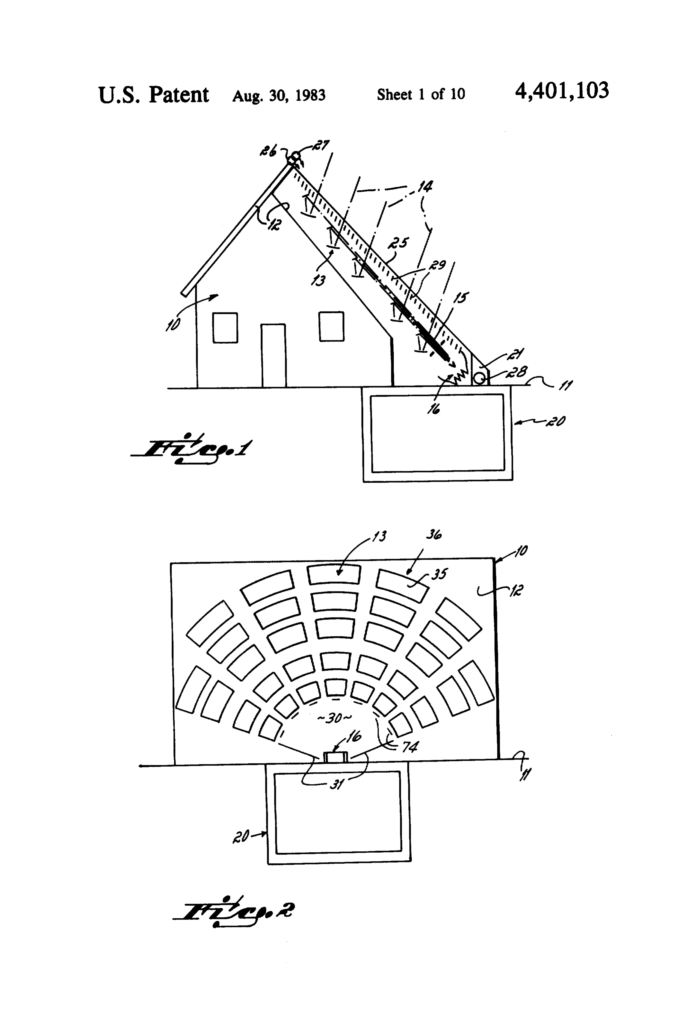
tor system except during the limited period of time. The several features and objectives of the invention Another form for solar energy conversion has been called a power tower. The power towers which have 55 will become more readily apparent from the following detailed description taken in conjunction with the ac been principally disclosed consist of a plurality of re companying drawings in which: flectors mounted on the ground or on terraced struc FIG. 1 is a diagrammatic elevational view taken from tures built for that purpose to cover a very sizeable area.
A central target is provided and the reflectors are ar theFIG. west side of a dwelling;
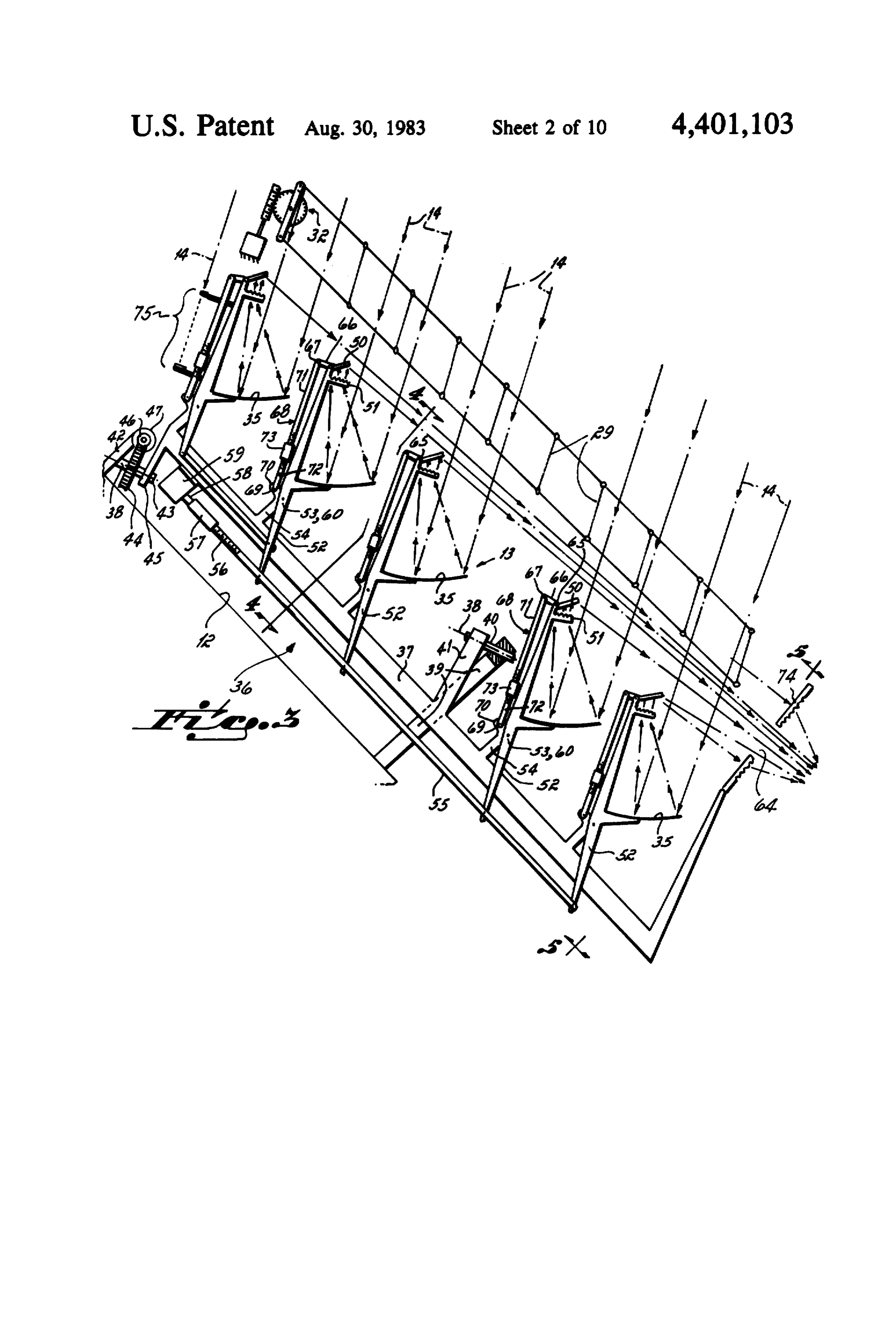
2 is a diagrammatic elevational view partly in ranged to receive energy from the sun and direct it to the target in the tower. Usually, provision is made for section taken from the south of the dwelling; driving the reflectors either individually or in groups so FIG. 3 is a diagrammatic, side elevational view of a as to track the sun as it passes from horizon to horizon. group of collector units;
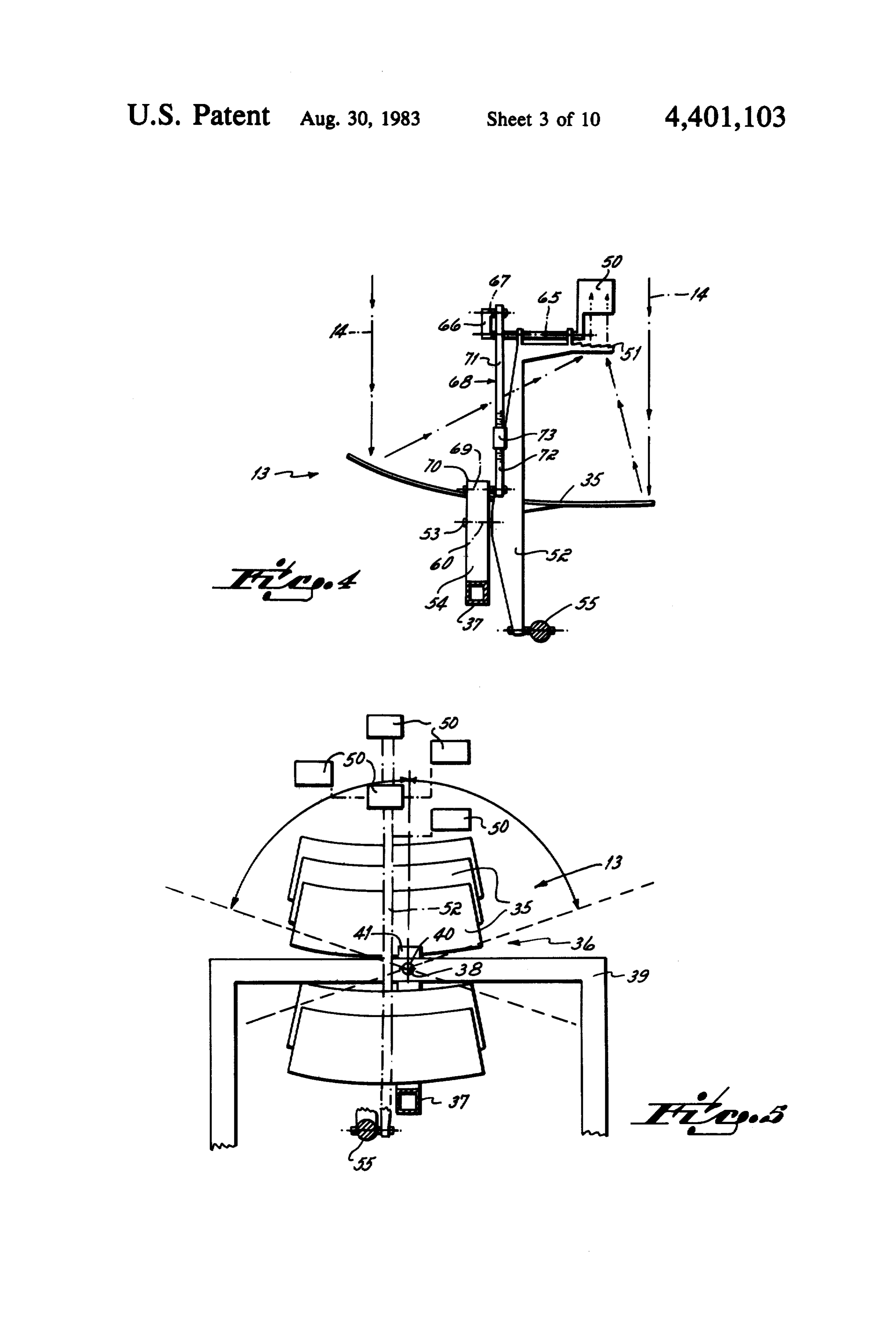
The power tower is a much more practical type of FIG. 4 is a cross-sectional view taken along lines 4-4 energy converter in the utilization of systems for track 65 of FIG. 3 illustrating one collector unit of the group; ing the sun and in the reflecting of radiant energy di FIG. 5 is a cross-sectional view taken along lines 5-5 rectly to target as contrasted to the utilization of a fluid of FIG. 3 illustrating the group of collector units pri medium as described above. marily in end elevation;
Page 13scan →
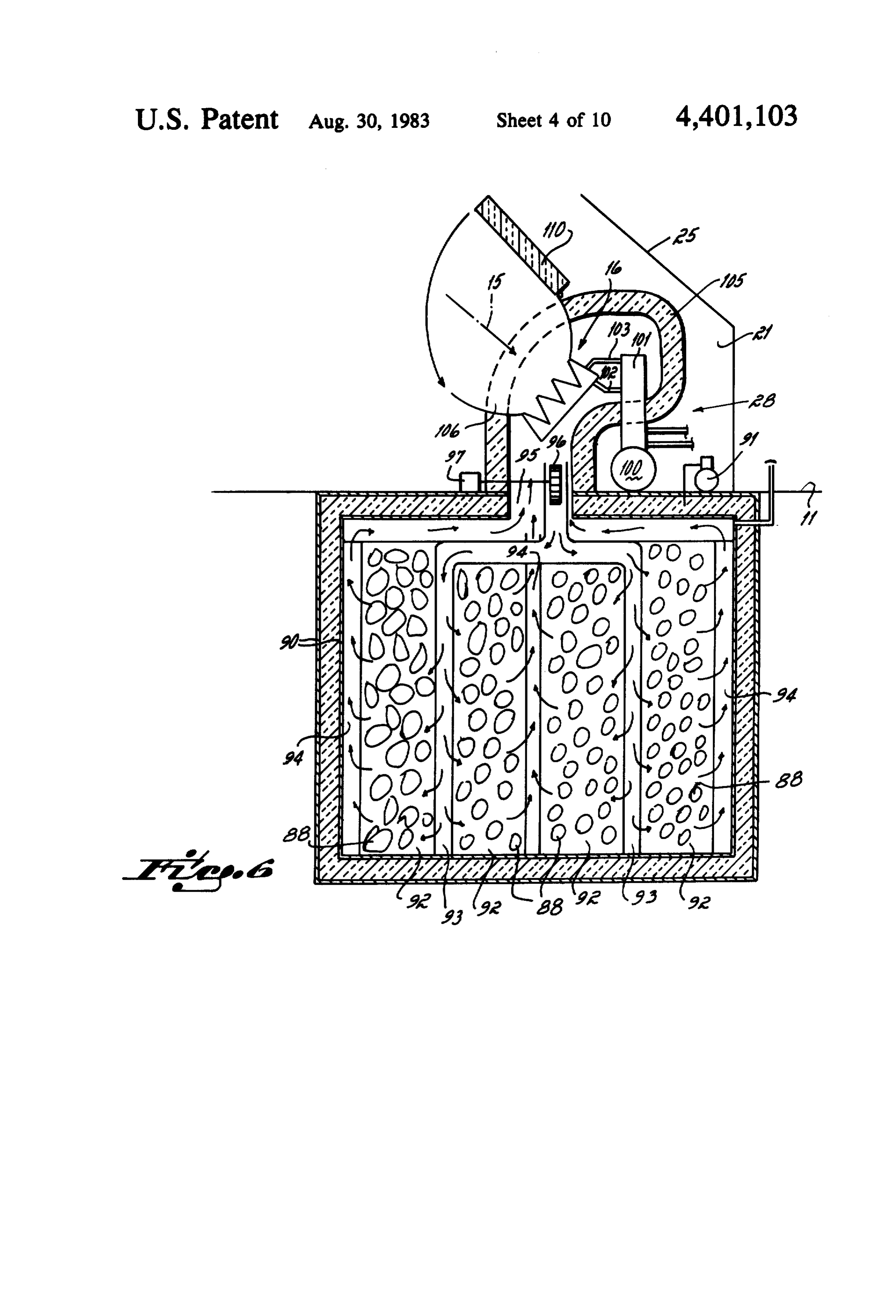
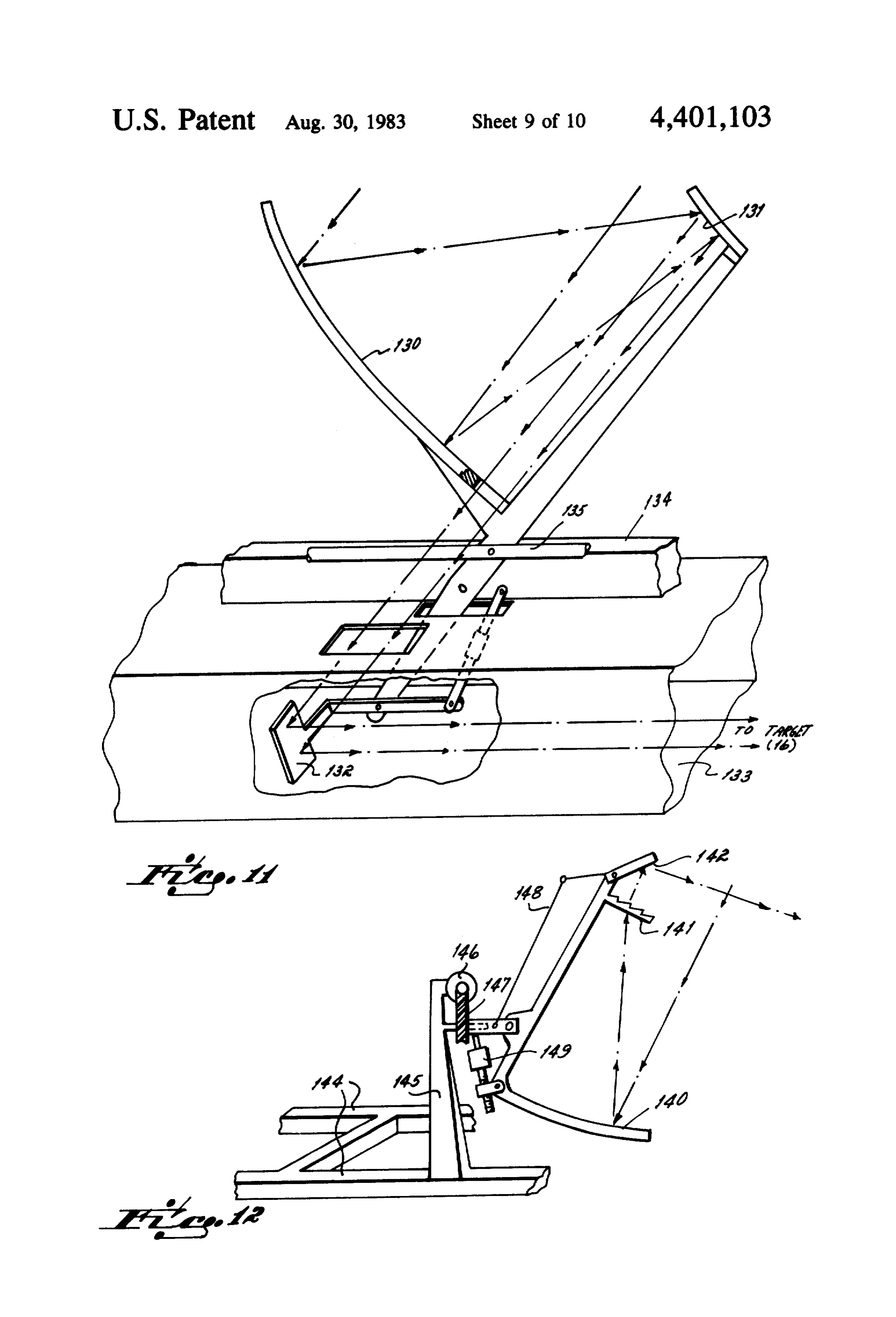
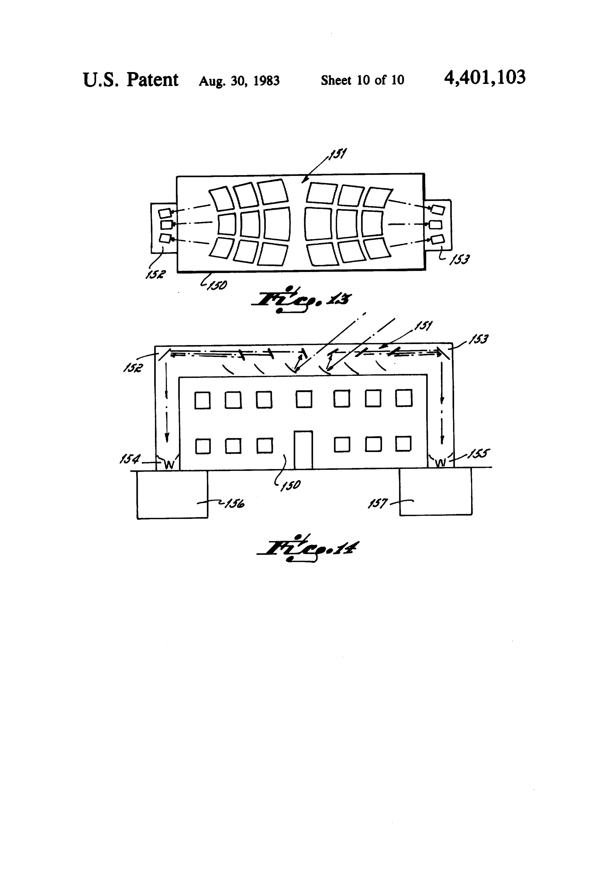
FIG. 6 is a diagrammatic cross-sectional view of the In the operation of the system, the incident rays of portion of the system which includes the target and the solar energy 14 impinge upon the individual collectors. storage system; The reflectors and/or lenses of the individual collectors FIG. 7 is a diagrammatic perspective view with por concentrate the solar energy impinging on a wide area tions broken away illustrating the target; into a small column of energy which is directly trans FIG. 8 is a disassembled perspective view partly mitted to the target 16. The combined effect of the broken away illustrating a target element; columns of radiant energy from the several groups of FIG. 9 is a flow sheet of the solar energy conversion collectors which form the array is to create an ex system; tremely high temperature at the target of, for example, FIG. 10 is a graphic display of the manner in which O 1500 F. A fluid medium such as air is circulated around the total energy received is broken up into losses, en and through the target, which acts as a heat exchanger, ergy used and the like over a twelve month period; so that the heat of the target created by the sun's energy FIG. 11 is a diagrammatic perspective view of an is given up to the air. The air is then forced through the alternative collector system; storage room where it transfers its heat to a storage FIG. 12 is a diagrammatic perspective view of an 15 medium such as rocks. Heat can be transmitted directly alternative collector and tracking system; from the target to the engine/generator combination 28. FIG. 13 is a diagrammatic top plan view of an alter Alternatively, heated air can be directed from the stor native layout for a solar energy system for a larger age room to the target and thence to the engine/genera establishment; tor combination in order to generate the electricity FIG. 14 is a diagrammatic elevational view, partly in 20 needed dwelling to satisfy the general energy requirements in the during periods when no sun impinges on the section, of the establishment of FIG. 13. collector array.
GENERAL, ORGANIZATION The heat discharged from the engine to a cooling fluid may be used for space heating the dwelling or may
The general organization of the system of the present 25 be invention is illustrated in FIGS. 1 and 2. There, a dwell used to supply energy for air conditioning equipment ing 10 projecting above the ground 11 has a pitched in the summer.
roof 12. The invention could be used with a dwelling Collector System having a flat roof, but such a dwelling would require a The collector system (FIGS. 3, 4 and 5) includes a different arrangement for the collector system, as can be 30 plurality of primary reflectors 35, the reflectors being seen with reference to FIGS. 13 and 14. Mounted on the roof is an array of collectors 13. Each collector in the matically illustrated in FIGS. 3 atobar5,37.theAsbar array concentrates solar energy indicated at 14 and mounted for rotation about a tracking axis 38. A support transmits that energy, as indicated by the arrows 15, to frame 39 mounted on the roof carries a pin 40 to which a target 16. The target 16 is adjacent a storage room 20 35 an arm 41 fixed to the bar 37 is rotatably mounted. which is located below ground level. Immediately Another support frame 42 mounted on the roof adjacent above the storage room and adjacent the target is a the upper end of the bar 37 carries a shaft 43 which is power room 21 which contains accessory elements such rotatably mounted in the support frame 42. The shaft 43 as an engine (preferably a Stirling engine) and generator has a pinion gear 44 and has fixed to it an arm 45 which combination 28 for converting the solar energy to elec is integral with the bar 37. The pinion gear 44 is en trical energy. On the opposite side of the target 16 a gaged by a worm gear 46 which is driven by a tracking room is provided to contain power conditioning equip motor 47.
ment, microprocessor controls and monitors, electrical In the illustrated form of the invention, each collector storage batteries, air conditioning unit, vacuum pump, unit includes a primary parabolic reflector 35 and a etc. which control and utilize the solar energy. 45 secondary flat reflector 50. Interposed between the The collector array is preferably enclosed by a trans primary and secondary reflectors is a Fresnel lens 51. parent roof 25. The transparent roof is preferably The reflectors 35, 50 and lens 51 are carried on a lever equipped with a cleaning system 26 consisting of means 52 which is pivoted at 53 to a post 54 projecting from for discharging a stream of water across the roof to the carrier bar 37. A tracking link 5.5 extends substan wash away particulate material which may have settled tially the length of the bar 37 and is threaded at 56 at its on the transparent roof between cleaning periods. A upper end. The threaded upper end 56 is received in an similar emergency protection system 27 may optionally internally threaded sleeve 57 which is fixed to a shaft 58 be provided for discharging an opaque fluid across the of a tracking motor 59. The tracking motor 59 rotates transparent roof in order to block out substantially all shaft 58 causing the link 55 to extend or retract which in solar energy in the event of malfunction and in order to 55 turn causes the lens assembly to pivot about an axis 60 permit emergency repairs to be made on the collector (FIG. 4) at the pivot 53.
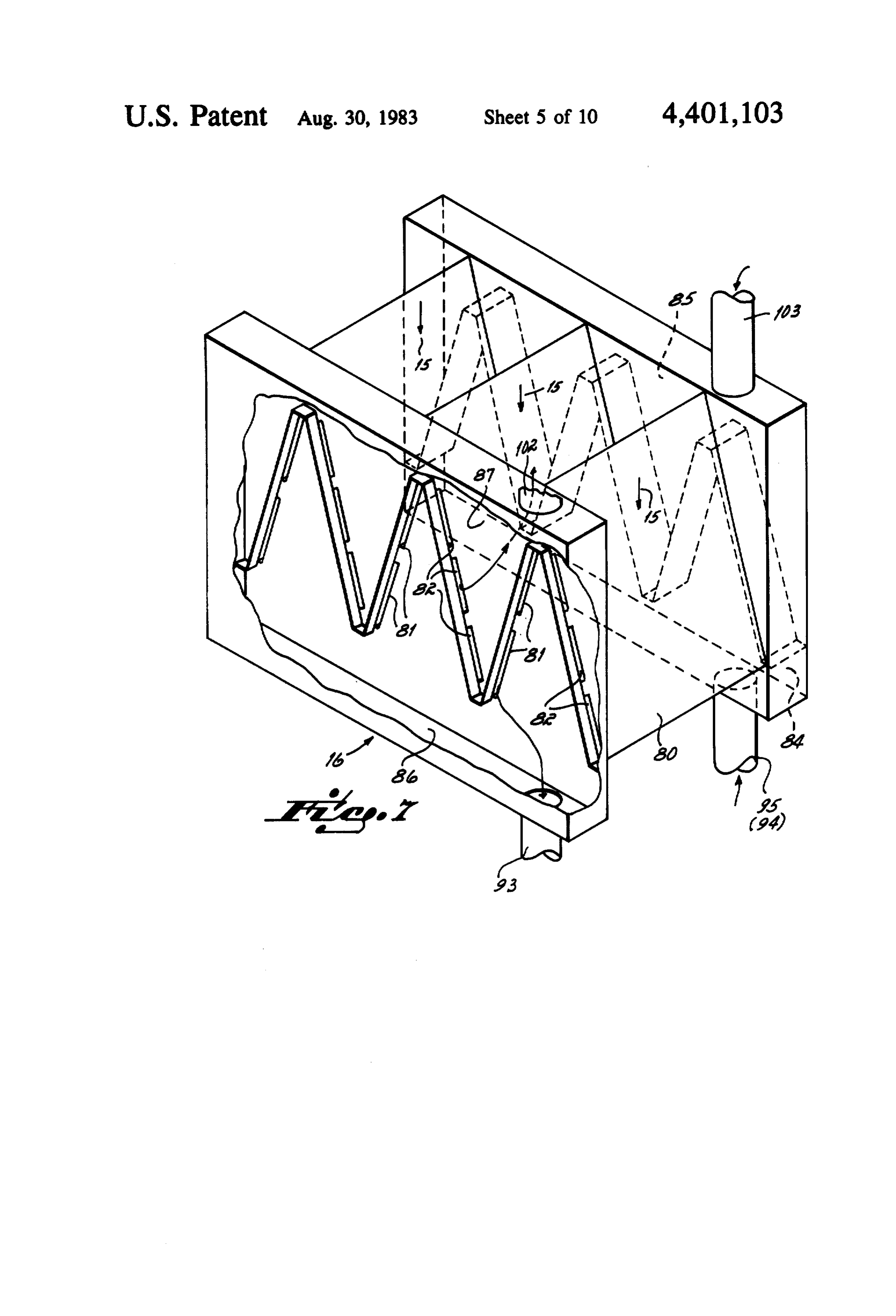
system. Alternatively and preferably, a system of lou The secondary reflector 50 is pivoted at 65 to the vers 29 is positioned under the transparent roof 25. lever 52 and has an arm 66. The arm 66 is pivotally Tracking means 32 (FIG. 3) are provided to maintain connected at 67 to a link 68 which is pivoted at its other the plane of the louvers parallel to the sun's rays during end at axis 69 to an extension 70 of the post 54. The link normal operation. In emergencies the tracking means 32 68 is formed of two elements 71 and 72 interconnected will shift the louvers to a position totally blocking out by a threaded sleeve 73 which permits the length to be the sun's rays, thereby shutting down the system. varied in order to adjust the output direction of the The space 30 between the collector array 13 and the secondary reflector. The distance between pivot points target 16 is surrounded by a shield 31 which prevents 65 65 and 67 is twice that of the distance between pivot any living thing from passing through the area where points 53 and 69. Thus, when the tracking link 5.5 causes highly concentrated sun's rays are transmitted to the the lever 52 and the primary parabolic reflector to target 16. swing through an angle, the secondary reflector will 14 swing through half that angle with respect to the arm 52 In the form of the invention illustrated in FIGS. 7 and in order to maintain the radiation from the secondary 8, the target consists of a series of flat heat exchangers reflector directed onto the target 16. 80 which are interconnected in a zigzag form as illus It appears to be extremely important that there be a trated in FIG. 7. Each heat exchanger has two sets of precise 2:1 ratio between the movement of the second slots 81, 82. As viewed in FIG. 7, the slots 81 in the downward-facing portions of the heat exchanger 80 are ary reflector 50 and the primary reflector 35 in order to prevent an undesirable beam divergence. It would be connected to the circulation system for storage, as will described in more detail below. The slots 82 in the therefore be preferred to utilize a nearly parallelogram upwardly-facing linkage driving a 2:1 gear at the secondary reflector O portions of the heat exchanger are rather than to have a pure linkage system illustrated. connected to accept the working fluid of the heat en As best seen in FIGS. 3 and 4, the incoming rays from gine, also to be described in greater detail below. The the sun are parallel and impinge upon the primary para slots for the storage system are of substantially larger bolic reflector 35. There, the rays are converted until size and greater volume than the slots for the Stirling they strike the Fresnel lens 51. The Fresnel lens 51 15 volumesystem.
engine of the
Since the latter form part of the working engine, engine efficiency is enhanced by converts the converging rays to parallel rays which low volume. On the storage side this constraint is ab impinge upon the secondary reflector 50 and are then sent, and somewhat larger slots are desirable to avoid directed in parallelism, as at 15, toward the target 16.
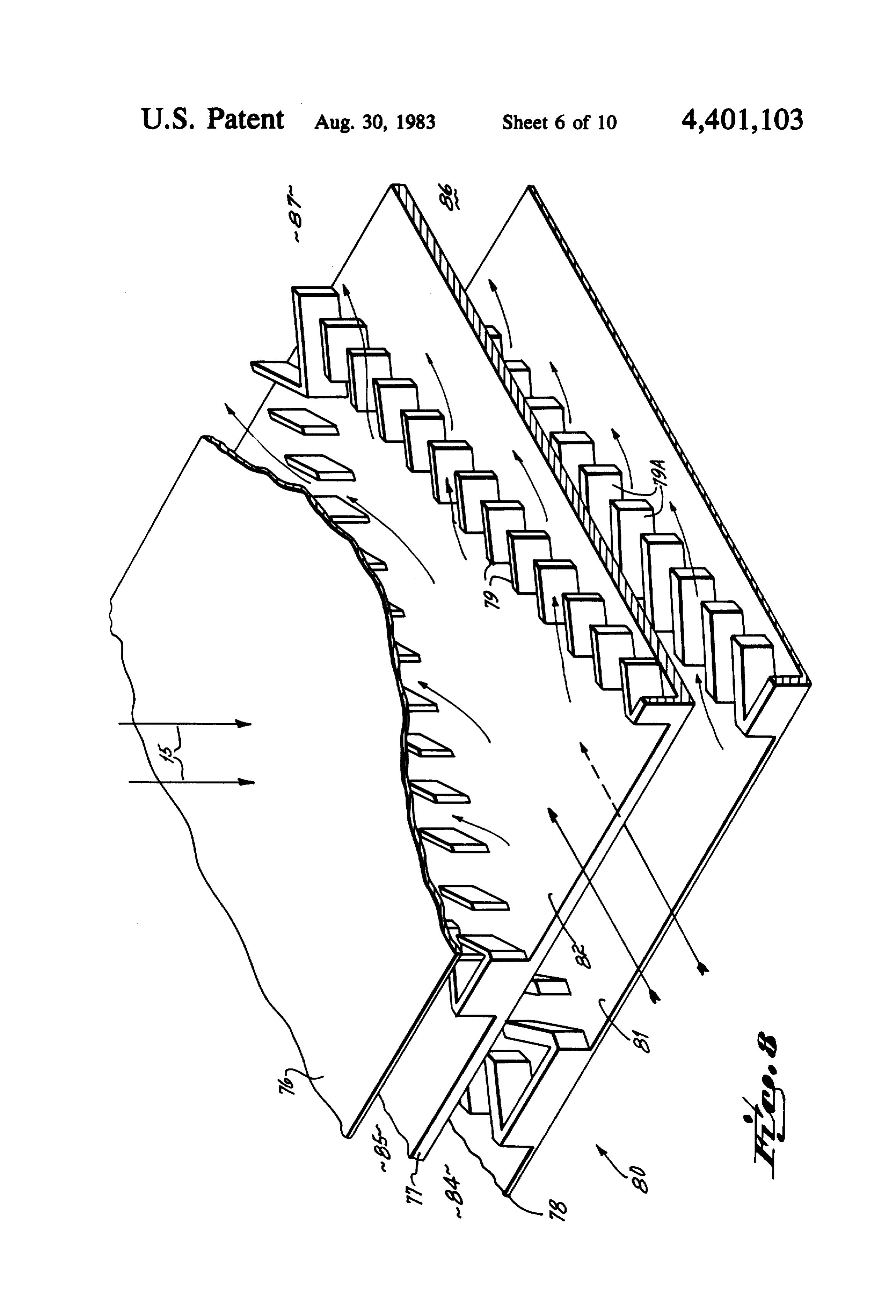
The flat reflector may be given a slight curvature in clogging from particlates. order to tend to cause the rays 15 to converge slightly andEach group of slots has its own inlet header (84, 85) outlet header (86, 87), the headers 84, 86 being in order to offset any divergence due to distortion in the provided reflector and lens system and due to the finite size of the headers 85,for87 thefor storage circulation system and the the engine and generator circulation solar disk. As shown in FIG. 5, the secondary reflectors system. The heat exchangers may be formed from cop 50 are in staggered relationship to one another so that per, stainless steel, ceramic, graphite or composite mate the lower lenses of the group do not obstruct transmis 25 rials.
sion of radiant energy from the upper reflectors. The orientation of the target is such that the concen To further correct for a divergence, it is contem trated radiation 15 impinges on the plates at acute angles plated that a Fresnel lens be located immediately down to the surface of the plates. The zigzag form gives a low stream of the collector system for the purpose of captur frontal area for low heat losses (re-radiation and con ing stray rays and directing them toward the target 16. 30 vection) while giving large fin area. The Fresnel lens has an aperture 64 through which the As illustrated in FIG. 8, each heat exchanger plate is main body of the concentrated rays pass directly formed as a sandwich of an upper plate 76, a middle toward the target 16. That aperture 64 is surrounded by plate 77 and a lower plate 78 with good thermal con the Fresnel lens portion 74 so that the diverging rays are duct being maintained among all plates. The space be focused into the target. 35 tween the plates 76 and 77 carry fins 79 in compara A sun locator 75, which is a commercially available tively spaced relation, the fins 79 forming a V at a rela device, is mounted on each group in order to detect the tively acute angle. The low volume fluid passing around position of the sun and to generate signals to the track the fins 79 through the space between the plates 76 and ing motor 47 of axis 38 and the tracking motor 59 of axis 77 is directed to the Stirling engine. 60 in order to cause the primary reflectors to follow the 40 Similarly, between the plates 77 and 78 are fins 79A, sun and receives as directly as possible the radiant en the fins 79A forming a V at a larger angle than that ergy from the sun. The axes 38, 60 are perpendicular to formed by the fins 79. These fins 79A receive the air, at each other but not necessarily in the same plane. As high volume, passing through the space between the viewed in FIG. 2, for the central group of reflectors, the plates 77 and 78. The fins 79 and 79A should be integral rotation of the carrier bar about the axis 38 (azimuth 45 with both adjacent plates between which they are se tracking) primarily causes the collector group to follow cured. The fluid passing through that space picks up the the sun as it moves from the east horizon to the west heat created at the target and delivers it to storage dur horizon. The pivoting of the levers 52 about the axis 60 ing the time that the sun is shining on the system. At (elevation tracking) causes the individual collector units other times, the fluid conveys heat from storage to the to follow the sun in an elevational track as the sun 50 target, giving up heat to the target which is in turn moves between its lowest and highest positions with picked up by the fluid passing through the alternate respect to the horizon. For the outboard group of re space between plates 76, 77 which is directed to the flectors, the tracking east to west and low to high is Stirling engine.
shared by the rotation with respect to both axes. In Storage Room (Heat Storage System) either event, it is the combined motions which keep the 55 primary reflector directed at the sun all day. A typical storage room is illustrated in FIG. 6. The In general. the collection system is of lightweight storage room is preferably located immediately adja design, since there are no forces on it other than its own cent the target 16 so that the system will incur minimal weight. Foamed and reinforced plastics can be exten heat losses due to transmission of heat from the target to sively used. the storage room. A blower 96 having a motor 97 is Target provided to force the circulation of air between the target and the store room. Air is preferred for simplic
The overall function of receiver or target 16 is to ity, but other high temperature fluids are not precluded. convert concentrated radiation into sensible heat; send Note that this air is never cold. Typically it would pick that to the heat engine or to storage or both; send stored 65 up heat at perhaps 1550 F. and deliver it to a body heat to the engine when there is no sun; and to do these already at 1500" F. The storage room is totally enclosed at good thermal efficiency without significant moving by walls 90 of insulative material. If possible, the walls parts. should consist of dual walls having space in between 15 with provision for evacuating the walls by means of a of the target 16 to approximately 1550 F. and to deliver vacuum pump 91, as indicated. approximately 0.6 million Btu during an average winter Contained within the storage room are multiple com day to the target. When the sun has passed below the partments 92 containing a thermal media 88 in the form western horizon, or when clouds appear, the cover 110 of bricks, rocks, or other material which can absorb is closed over the target by photoelectric control means sensible or latent heat. Inlet passageways 93 are pro so as to minimize the escape of heat from the target, vided for the flow of heated air from the target into the engine, storage room and the like. The energy absorbed storage room. The passageways are perforated so as to by the target 16 is picked up by the air which continu permit flow of the air from the passageways 93 into the ally flows through the first set of slots 81 carrying the compartments 92. Return passageways 94 are also pro 10 heat away from the target. The thus heated air passing vided. Return passageways are also perforated so as to through the storage room gives up the heat to the ther permit the air, after it has given up its heat to the ther mal media 88. High temperature heat from the system, mal medium, that is, the rocks, to pass into the return that is, from the storage room or from the target itself, passageways 94. The air returned from the storage is used principally for driving the engine which in turn room through the passageways 94 would pass through 15 drives the generator to create electrical energy. Low a passageway 95 into the inlet header 84 to the target 16 temperature heat carried from the engine by a cooling where additional heat is picked up from the target. medium through a heat exchanger system, not shown, is The same air circulation occurs for heat withdrawal used for space heating or for absorption-type air condi from storage, except then the target 16 is slightly cooler tioning. In operation it is preferred that the target 16 be and picks up heat. kept hot at all times so that the Stirling engine has heat The passageways to the headers 84, 85, 86, 87 are not for operation on demand.
illustrated in FIG. 6. It should be understood that the During the spring months, the heat delivered to the passageway 94 is connected to the inlet header 84 and store room is in excess of that which would be required the passageways 93 are connected to the outlet header for normal daily usage. At the end of the spring, the 86 of the target 16. 25 storage room should normally have approximately In the power room an engine, preferably a Stirling twenty-five days of stored heat for use without sun engine 100, is connected to a generator 101 to make up shine.
the engine/generator combination 28. The engine/gen During summer and fall, the excess heat may be used erator combination is connected by way of an inlet to generate surplus electricity for sale to a utility net passageway 102 to the discharge header 87 of the target 30 work.
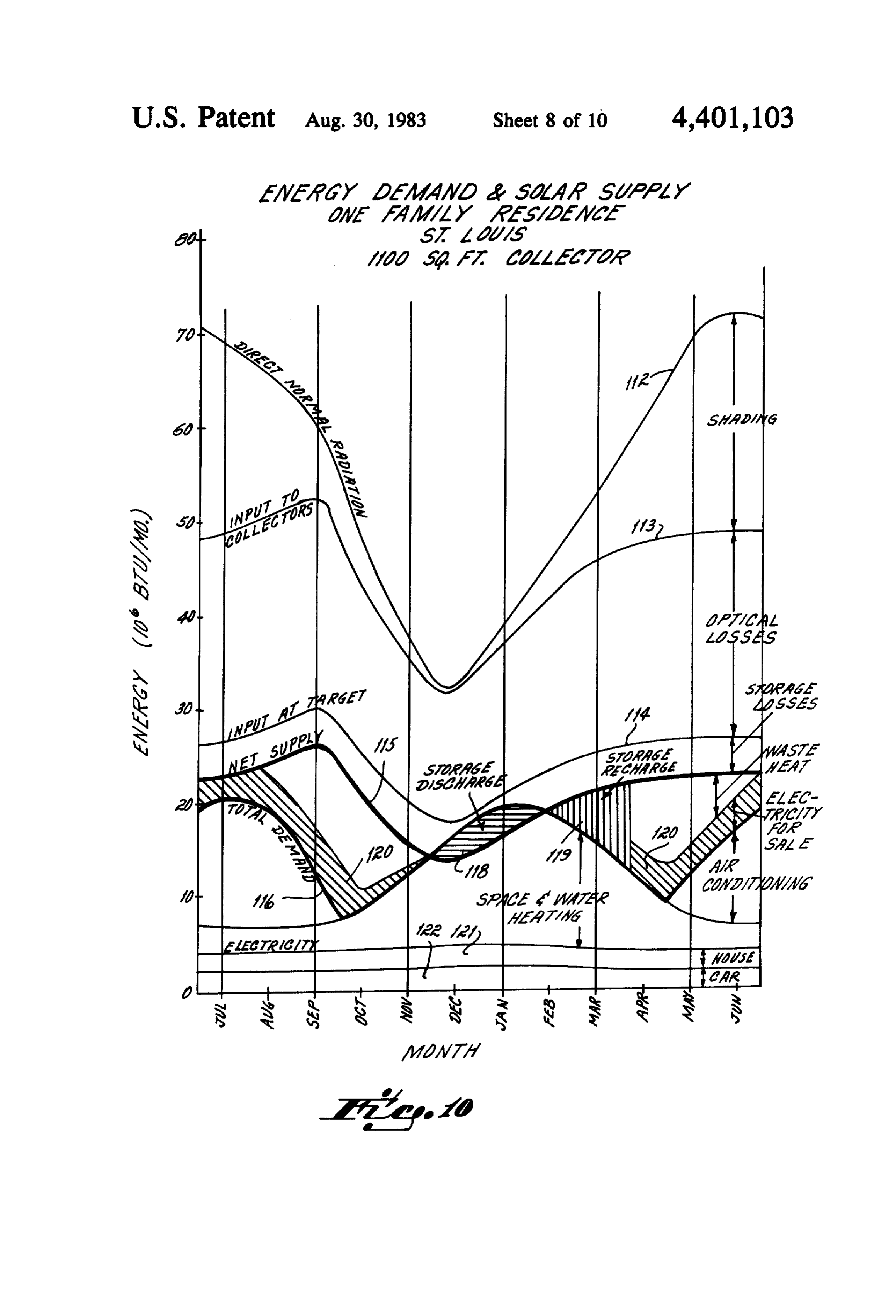
16 and air is returned to the target 16 by way of passage The curves of FIG. 10 illustrate generally the energy way 103 connected to the inlet header 85 of the target which would be available during different parts of the 16. year. By way of example, the energy available in a Other means for utilizing the heat of the solar energy typical year in St. Louis, Mo. is depicted. It is assumed to drive an engine connected to a generator in order to 35 that a single family residence has a 1100 sq. foot collec generate the usable voltage would be well within the tor to receive the solar energy, skill of the art. So also would non-heat-engine methods The uppermost curve 112 depicts the Btu emanating of electricity generation, such as photovoltaic, thermi from the sun which, if unshaded, would impinge upon onic, and thermoelectric devices. Heat engines are pre the collector. The curve 113 depicts the energy actually ferred, however. Cascaded types, e.g., heat engine plus 40 impinging on the collectors. The space between the thermoelectric, are also practical. Insulation 105 includ curves 112 and 113 illustrate average losses arising out ing a pivoted cover 110 surrounds most of the target of shading by adjacent collectors.
except for the opening 106 through which the collected The curve 114 depicts the energy received at the sun's rays pass. The pivoted cover is preferably pro target 16. The space between the curves 113 and 114 vided with automatic controls for opening and closing it 45 represents the energy lost due to the optical system during periods when solar energy is available and un involved.
available, respectively. The insulation also surrounds The curve 115 depicts the actual energy available for the hot end of the Stirling engine. The opening 106 may work. The space between the curves 114 and 115 indi be covered by a window to inhibit heat losses by con cates the losses in the system which are primarily stor vection and re-radiation when the cover 110 is open. SO age losses.
The curve 116 illustrates the total dermani. it can be
Operation seen that the total demand is higher in the winter and On any sunny day, the sun locator 75 will control the summer months due to the need for greater heating and motors 47 and 59 of each group of collectors to rotate cooling. For most of the year, the net supply curve the bar 37 and to reciprocate the link 5.5 in order to aim 55 15) is greater than the total demand (curve 116. the primary reflectors with respect to the sun so that Around December through February, the demand they most efficiently capture the heat of the sun's radia will be normally greater than the supply. A section 118 tions. Each primary reflector 35 causes the sun's rays to which is cross hatched is indicative of a discharge from converge and to pass through a Fresnel lens associated storage in order to supply the energy requirement. It with it. The parallel rays emanating from the Fresnel O should be observed that that energy in the cross hatched lens are then reflected from a flat mirror directly to the area 118 is considerably less than the excess between target 16 in a very concentrated form. Because the supply and demand in the other areas and hence there reflector and lens system is located above the carrier bar should always be a comfortable annount of energy in 37, there is only minimal obstruction and interference storage available for use when the demand exceeds the with the sun's rays impinging upon the array of collec 65 daily supply.
tOS. The area cross hatched at 119, where supply is The combined effect of the array of collectors direct greater than demand, indicates storage recharge. When ing sunlight to the target 16 is to raise the temperature sufficient energy is in storage, the remaining energy 16 received which is in excess of demand generates elec system in which the energy is concentrated by the re tricity which can be sold to local utilities. That electri flectors and directed in a concentrated form to a target. cal energy is indicated at 120. The previous embodiments have contemplated a Included below the total demand curve is energy solar energy system for a single dwelling, the system used for space and water heating, the electricity nor being located on the pitched roof of the dwelling. mally used in the home as depicted by the block 121 and Alternative systems for different types of buildings energy needed to operate an electric vehicle indicated are within the scope of the present invention. One such in the block 122. alternative system is depicted in FIGS. 13 and 14. The chart of FIG. 9 illustrates the manner in which There, a large building, perhaps an industrial building, is the energy is received from the sun and converted to 10 indicated at 150.
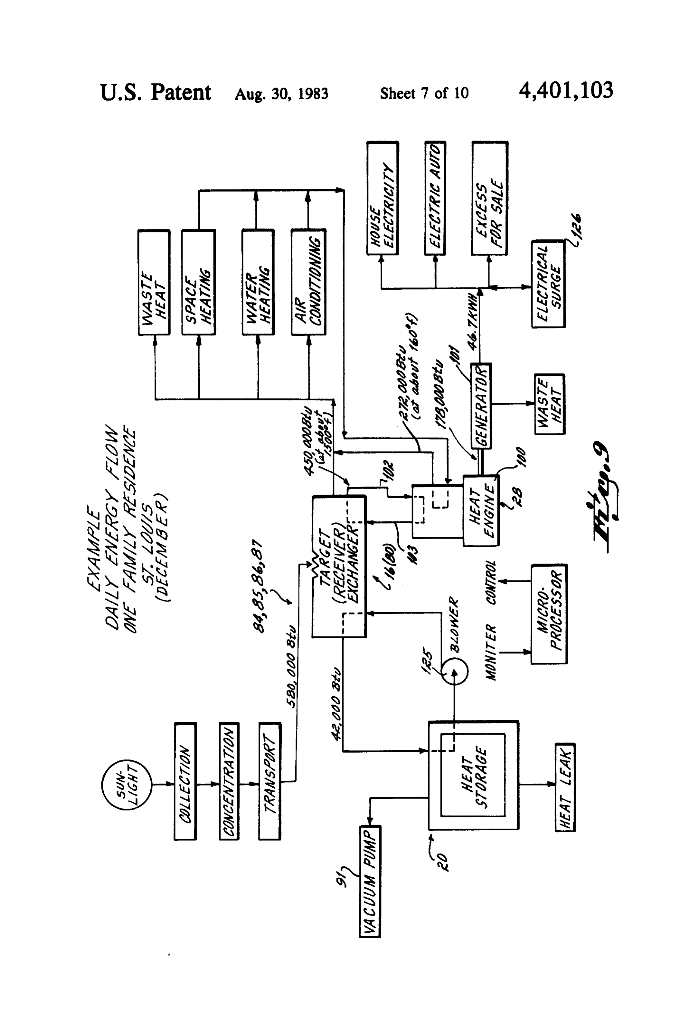
useful power in the system depicted in FIGS. 1-8. The flat roof of the building has two sets of reflector On a typical day, the sunlight, with losses in the col systems 151, the reflector systems being oriented to lection, concentration and transportation from the col direct a concentrated beam toward reflectors 152 and lector to the receiver, delivers 580,000 Btu to the target 153 at the corners of the building. At the base of each 16. Of that, 42,000 Btu might be sent to storage. The air 15 end of the building a target 154 and 155 is located, each carrying the energy is circulated by a blower 125. target being associated with other equipment of the 450,000 Btu are directed to the heat engine 28 driving type previously described, including a storage area 156, the generator to create electricity for home use, an 157.
electric automobile and any excess for sale. A battery In addition to the configuration thus far described, it bank indicated at 126 is available for surges beyond the 20 should be understood that the collector systems would capacity of the generator. not have to be mounted on the roof of the building for It is contemplated that air would be circulated to the which they are designed. Rather, they could be cool side of the heat engine and that would deliver mounted on the ground. However, since the system of 272,000 Btu for air conditioning, water heating, space the present invention is primarily for use in heating heating and the like. 25 single family residences, in some situation the mounting In the event excess heat is developed at the cool side of a collector system of the order of 1,000 sq. feet on the of the heat engine and which cannot be otherwise used, ground also would require extra shielding to prevent it could be dissipated through a water system on the inadvertent contact by living things.
shaded side of the roof. I claim:
30 1. A solar energy conversion system comprising,
ALTERNATIVE EMBODIMENTS a target,
FIG. 11 illustrates an alternative optical system. It an elongated bar substantially longitudinally aligned includes a primary reflector 130 which receives the with said target, means for rotating said bar about sun's rays directly. The primary reflector concentrates a first axis pointed at said target, that energy and reflects it onto a secondary reflector 35 a plurality of longitudinally spaced collector units 131. Generally parallel rays from the secondary reflec mounted on said bar, means to rotate each said unit tor are directed to a tertiary reflector 132 located within about a second axis which is generally perpendicu a housing 133. A suitable carrier 134 for a plurality of lar to said first axis, the reflectors just described is provided and a tracking each said collector unit having a first receiving ele link 135 is provided to enable the reflector system to 40 ment causing the sun's rays to converge, a second follow the sun as previously described. In this embodi element adjacent said first element for receiving ment, the sun's rays are directed to the target 16 gener said converging rays and forming a narrow beam ally below the reflector system as contrasted to the of substantially parallel rays, a third element adja original embodiment. The path of the rays to the target cent said second element for directing said beam to 16 is through a protective housing 133. 45 said target, and means for moving said third ele In the previous embodiments, groups of collector ment relative to said first element. systems have been ganged together on a common car 2. A conversion system as in claim 1 further compris rier bar, such as bar 134, and the reflectors track the sun 1ng, in unison through the rotation of the carrier system for lens means between said collector units and said tar the reflectors. SO get to further concentrate said energy before it In the embodiment of FIG. 12, a system is diagram impinges on said target.
matically illustrated in which units are provided with 3. The system as in claim 1 further comprising, independent tracking means. A primary reflector 140 a transparent housing overlying said plurality of col directs incoming rays through a Fresnel lens 141 to a lector units to protect them from particulate matter secondary reflector 142 and thence to target 16. This 55 in the atmosphere, and reflector system is mounted, along with as many other means for cleaning the dust from said housing. reflector systems as are required, on a frame 144 by 4. The system as in claim 1 further comprising, means of a bracket 145. The bracket carries a motor 146 a louvered screen covering said collector units for operating through a gear train 147 and rotates the re temporarily shutting said system down, and flector system to follow the sun from horizon to hori means for normally maintaining said louvers parallel Z). to the sun's rays,
A motor 149 is connected to the primary reflector 5. A solar energy conversion system for a dwelling and a linkage system 148 is provided to cause the reflec having a roof, the system comprising, tor system to track the sun from its lowest to its highest a small target for receiving concentrated solar energy points on the horizon. 65 and located close to said dwelling, A wide variety of reflector systems can also be cre an array of individual collector units mounted on the ated without departing from the scope of the present roof of said dwelling, said collector unit being invention which has as a primary concept a collector mounted on a plurality of bars, said bars being 17 mounted on said roof in spaced relation to each each collector unit having a first receiving element other, means for rotating said bars about one axis causing the sun's rays to converge, a second ele and means for rotating said collector units about a ment adjacent said first element for receiving said second axis to track the sun, converging rays and forming a narrow beam of each collector unit comprising, substantially parallel rays, a third element adjacent a support lever pivoted to said bar for movement said second element for directing said beam to said about said second axis, target, and means for moving said third element a primary reflector mounted on said lever and a relative to said first element, secondary reflector pivotally mounted on said means for rotating each said collector unit individu lever for movement about an axis parallel to said 10 ally about two axes perpendicular to each other to second axis, track the sun as it moves substantially from horizon means for rotating said secondary reflector at one to horizon, half the speed of said primary reflector, a louvered screen covering said collector array for said primary reflector receiving energy from the temporarily shutting said system down, and means sun and transmitting it via said second reflector for normally maintaining said louvers parallel to to said target. the sun's rays.
6. A solar energy conversion system for a dwelling 9. A solar energy conversion system for a dwelling having a roof, the system comprising, having a roof, the system comprising, a small target for receiving concentrated solar energy a small target for receiving concentrated solar energy and located close to said dwelling, 20 and located close to said dwelling, a storage system close to said target for receiving and a storage system close to said target for receiving and storing heat transmitted from said target in the storing heat transmitted from said target in the form of a hot fluid, said target including means for form of a hot fluid, converting radiant energy impinging on said target said target including means for converting radiant to a hot fluid, 25 energy inpinging on said target to a hot fluid, means for directing said fluid to said storage system, means for directing said fluid to said storage sys said fluid giving up its heat to said storage system, tem, said fluid giving up its heat to said storage an array of individual collector units mounted on the system, roof of said dwelling, said collector units being said target comprising, mounted on a plurality of bars, said bars being a housing which presents a large surface area for mounted on said roof in spaced relation to each impingement of said concentrated energy, other, means for rotating said bars about one axis two separate passageways in said housing, and and means for rotating said collector units about a inlet and outlet headers for each said passageway, second axis to track the sun, an array of individual collector units mounted on the each collector unit comprising, 35 roof of said dwelling, a support lever pivoted to said bar for movement each collector unit having a first receiving element about said second axis, causing the sun's rays to converge, a second ele a primary reflector mounted on said lever and a ment adjacent said primary element for receiving secondary reflector pivotally mounted on said said converging rays and forming a narrow beam lever for movement about an axis parallel to said of substantially parallel rays, a third element adja second axis, cent said second element for directing said beam to means for rotating said secondary reflector at one said target, and means for moving said third ele half the speed of said primary reflector, ment relative to said first element, said primary reflector receiving energy from the means for rotating each said collector unit individu sun and transmitting it via said second reflector 45 ally about two axes perpendicular to each other to to said target. track the sun as it moves substantially from horizon 7. A solar energy conversion system as in claim 6 in to horizon, which said primary reflector is parabolic and of substan a heat engine and electrical generator, tial dimension so that the array of reflector units collec means connecting one of said passageways to said tively receive a substantial amount of energy, 50 heat engine to circulate fluid from said passage a Fresnel lens interposed between said primary and ways to said engine, secondary reflector, and means connecting the other of said passageways said secondary reflector being generally flat and sub to said storage system to circulate fluid from said stantially smaller than said primary reflector. passageway to said storage system. 8. A solar energy conversion system for a dwelling 55 10. The system as in claim 9 in which said engine has having a roof, the system comprising, a hot side to which air from said target is directed to a small target for receiving concentrated solar energy drive said engine, and a cool side from which waste heat and located close to said dwelling, is exhausted, a storage system close to said target for receiving and means connecting said cool side to apparatus in said storing heat transmitted from said target in the dwelling for utilizing said waste heat for space form of a hot fluid, heating and the like.
said target including means for converting radiant 11. A solar energy conversion system for a dwelling energy impinging on said target to a hot fluid, having a roof, the system comprising, means for directing said fluid to said storage sys a small target for receiving concentrated solar energy tem, said fluid giving up its heat to said storage and located close to said dwelling, system, a storage system close to said target for receiving and an array of individual collector units mounted on the storing heat transmitted from said target in the roof of said dwelling, form of a hot fluid, 18 said target including means for converting radiant said converging rays and forming a narrow beam energy impinging on said target to a hot fluid, of substantially parallel rays, a third element adja means for directing said fluid to said storage sys cent said second element for directing said beam to tem, said fluid giving up its heat to said storage said target, and means for moving said third ele system, ment relative to said first element, a housing consisting of a sandwich of three spaced a shield surrounding the path of said concentrated parallel plates having a zigzag configuration to energy from said collector units to said target. create two passageways in the spaces between 13. A solar energy conversion system for a dwelling said plates, having a roof, the system comprising, fins in said passageways connected to said plates, O a small target for receiving concentrated solar energy and inlet and outlet headers for said passageways, and located close to said dwelling, an array of individual collector units mounted on the an array of individual collector units mounted on the roof of said dwelling, roof of said dwelling, said collector units being each collector unit having a first receiving element mounted on a plurality of bars, said bars being causing the sun's rays to converge, a second ele 15 mounted on said roof in spaced relation to each ment adjacent said first element for receiving said other, means for rotating said bars about one axis converging rays and forming a narrow beam of and means for rotating said collector units about a substantially parallel rays, a third element adjacent second axis to track the sun, said second element for directing said beam to said each collector unit comprising, target, and means for moving said third element 20 a support lever pivoted to said bar for movement relative to said first element, about said second axis, means for rotating each said collector unit individu a primary reflector mounted on said lever and a ally about two axes perpendicular to each other to secondary reflector pivotally mounted on said track the sun as it moves substantially from horizon to horizon. 25 lever for movement about an axis parallel to said 12. A solar energy conversion system comprising, second axis, a target, means for rotating said secondary reflector at one an elongated bar substantially longitudinally aligned half the speed of said primary reflector, with said target, means for rotating said bar about said primary reflector receiving energy from the a first axis pointed at said target, 30 sun and transmitting it via said secondary reflec a plurality of longitudinally spaced collector units tor to said target, mounted on said bar, means to rotate each said unit a transparent roof overlying said array of collector about a second axis which is generally perpendicu units to protect them from particulate matter in lar to said first axis, the atmosphere, each said collector unit having a first receiving ele 35 and means for cleaning said particulate matter from ment causing the sun's rays to converge, a second said transparent roof.k t element adjacent said first element for receiving
Provenance
- Collection
- Patents citing this work
- Pages
- 18
- Method
- pdftotext (the PDF's own text layer) + pdftoppm 300dpi page scans
- Patent office record
- patents.google.com →
- Source
- Google Patents citing-documents table
- Assignee
- Thompson Hugh A
- Published
- 1983-08-30
- Transcribed from
- patentimages.storage.googleapis.com →