

patent · US4294227A
Apparatus for heating water by solar heat
13 October 1981
Text
Page 1bibliographic recordscan →
United States Patent (19)
Kreibich et al.
54). APPARATUS FOR HEATING WATER BY
SOLAR HEAT
Inventors: Ursula Kreibich, Riehen; Rolf
Schmid, Gelterkinden, both of
Switzerland Assignee: CIBA-GEIGY Corporation, Ardsley,
30 Foreign Application Priority Data
Jun. 16, 1978 CH Switzerland ......................... 6581/78 Aug. 29, 1978 CH Switzerland ......................... 91 4/78 Int. Cl. ................................................. F24J 3/02 52 U.S. C. ................................... 126/400; 126/427;
3,931,806 l/1976 Hayes .................................. 126/400 4,040,566 8/1977 Chiarelli........ ... 237/1 A 4,063,546 12/1977 Schmid et al. . . 126/400 4,116,222 9/1978 Seifried ............ ... 126/435 4,169,554 10/1979 Camp ............ ... 126/427 4,184,635 l/1980 Bloomfield .......................... 126/419
FOREIGN PATENT DOCUMENTS
2270535 l/1976 France ................................ 126/400
Primary Examiner-James C. Yeung
Assistant Examiner-Robert J. Marett
Attorney, Agent, or Firm-Harry Falber
Apparatus comprising a solar collector, three heat ex changers operating at different temperature levels and connected in series on the service-water side, a latent heat store, various lines and valves, a circulating pump and an electrical operation-control circuit responsive to the temperatures sensed by various temperature sensors located in the above mentioned components. The two heat-exchangers operating at the higher temperature levels are each by-passed by a mixing valve on the ser vice-water side. Depending on the solar radiation or the temperature of the circulating medium, the heat ex changers at the higher or lower temperature level or combinations thereof are successively connected to the circulating medium.
18 Claims, 3 Drawing Figures
Tmin, set
Timit
Drawings
Page 2drawing sheetscan →
Page 3drawing sheetscan →
Page 4scan →
Apparatus for heating water by solar
Although the aforementioned kind of heat exchanger
Heat
is particularly advantageous, the storage and the heatex change operation could of course be allocated to sepa
Field of the invention
rate parts of the apparatus and the invention is in no way restricted to the boiler-like heat exchangers which
The invention relates to apparatus for heating water will be described in detail.
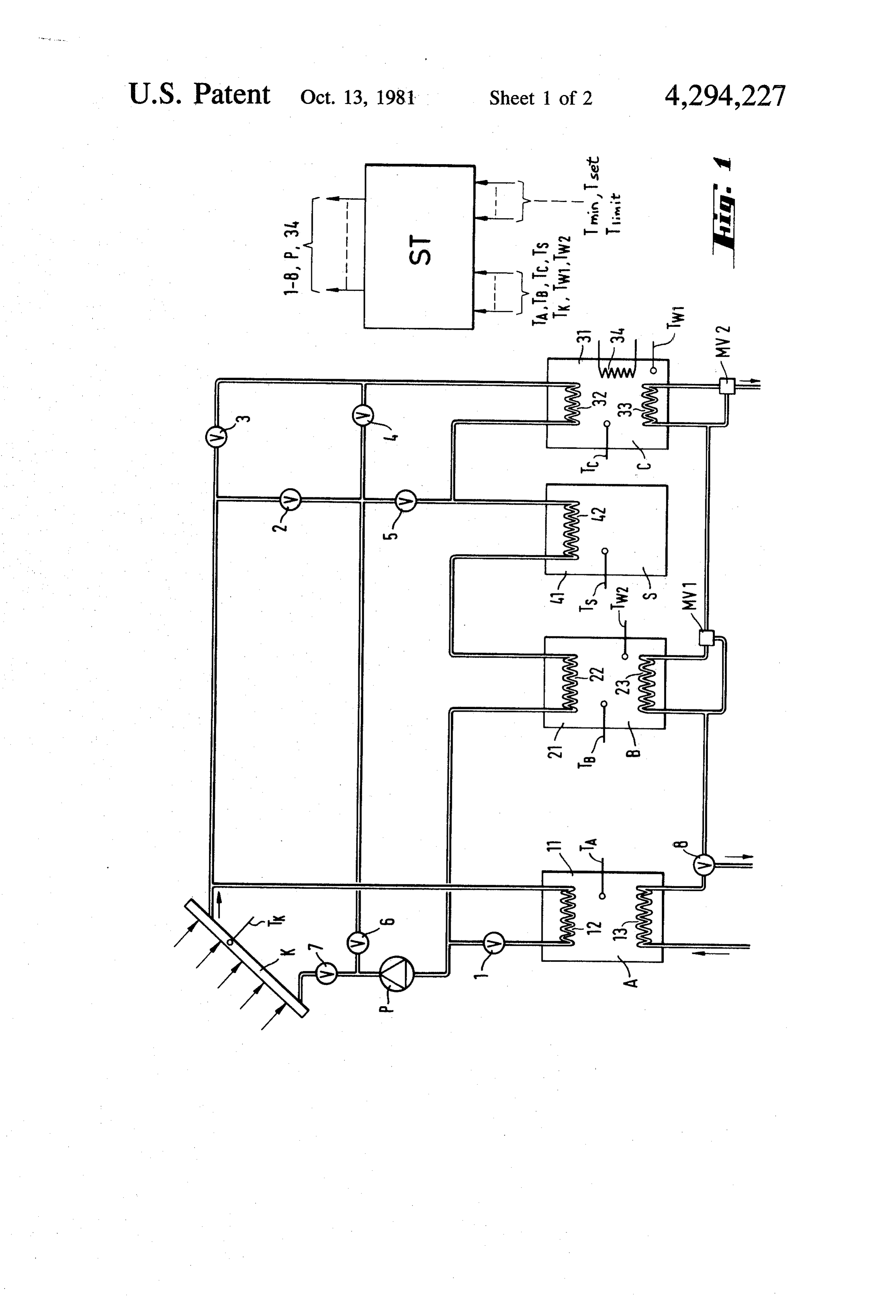
by solar energy and includes a solar collector coupled BRIEF DESCRIPTION OF DRAWINGS to first and second heat exchangers, one of which oper ates at a higher temperature than the other. A preferred embodiment of the invention will now be 10 described with reference to the accompanying draw
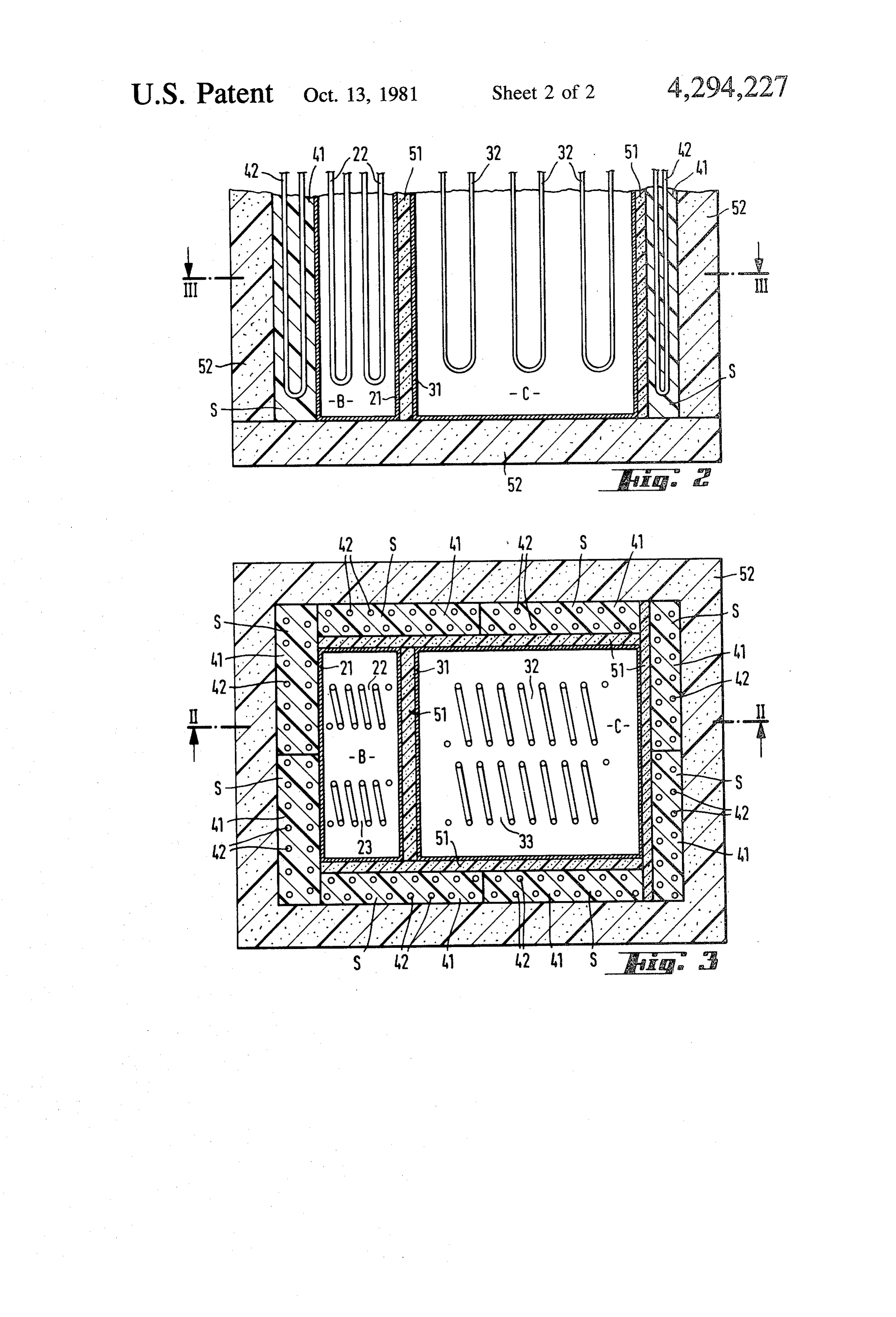
Numerous variants of devices using solar energy with FIG. 1 is a block diagram of apparatus in accordance have been exhaustively described in a number of publi this invention and cations, including the article by R. Scharer in "Elek 15 FIGS. 2 and 3 are two sections through a part of the trizitatsverwertung' No. 7/8 (1974) published by Elek apparatus shown in FIG. 1.
trowirtschaft, Zurich; in a lecture by E. Schnyder at the DETAILED DESCRIPTION OF PREFERRED "Heizen mit Sonne' Conference of the Schweizerische EMBODIMENT and Deutsche Gesellschaft für Sonnenenergie dated 8/9
November 1977 at Freiburg, W. Germany, and in 20 As shown in the figures, the apparatus comprises a "Solar Energy Thermal Processes' by J. A. Duffie and solar collector K, three heat exchangers, A, B and C W. A. Bechmann, Wiley Interscience 1974. All these connected in series on the service-water side, a latent devices suffer from the disadvantage that they do not heat store S, a circulating pump P, 8 valves 1-8, two make adequate use of solar energy, more particularly mixing valves MV1 and MV2 and lines or pipes (not the less valuable part at a lower temperature. denoted by reference numbers) connecting the afore A considerable improvement in this respect was 25 mentioned parts. The apparatus also comprises seven made by the two-stage solar energy installation de temperature sensors TK, TA, TB, TC, TS, TW and TW2 scribed e.g. in U.S. Pat. Spec. No. 4063546. This sys and a control circuit ST which is actuated by the sen tem comprises two substantially independent systems sors and actuates the valves 1-8. The temperature Sen each having a collector, a store and a heat exchanger, 30 sors detect the temperature of the water flowing in one system operating at a lower temperature and the collector K, the operating temperatures of the three other at a higher temperature. A similar installation but heat exchangers A-C, the temperature of store S and the temperature of the warm water leaving the heat without a latent-heat store is disclosed in Swiss Pat.
Spec. No. 578 718. It has been shown in practice, how exchangers B and C. For simplicity, the drawings do ever, that the efficiency of even the lastmentioned de 35 not show the connecting line between the control cir cuit and the temperature sensors or valves.
vice can be improved. The solar collector, the heat exchangers and the la OBJECT OF THE INVENTION tent heat store are of substantially known construction. An object of the invention therefore is to provide an Each heat exchanger substantially comprises a con apparatus that can make better, more economic use of 40 tainer 11, 21, 31, respectively, containing a heat-trans incident solar energy, or other forms of heat energy, water). Amedium mitting primary having a high thermal capacity (e.g.
coil 12, 22, 32 and a secondary coil than the prior art devices referred to above. (13, 23, 33) respectively are immersed in the medium. SUMMARY OF THE INVENTION The medium in the heat exchanger C may additionally In accordance with this invention therefore we pro 45 a material, e.g. paraffin which stores latent heat. The vide apparatus for heating water by solar energy com heat exchanger is also fitted with additional heating 34, prising a solar collector and a first and second heat such The as an electric heating coil.
latent heat store S substantially comprises one or exchanger connected in series on the service-water side, more blocks 41 (FIGS. 2 and 3) of cross-linked partly the first operating at a higher temperature level than the crystalline plastics in which a heat exchanger coil 42 is second, wherein a third heat exchanger is provided and 50 embedded.
operates at a lower temperature level than the second tioned kind is describedheat
A latent exchanger of the last-men heat exchanger and is connected in series with the other U.S. Pat. No. 4063 546.in detail in the above-mentioned two exchangers on the service-water side. Heat exchangers B and C and latent heat store S are The word "heat exchanger' as used herein means a combined into a compact structural unit. As shown by device for withdrawing heat energy from a heat trans 55 the sectional fer medium, storing at least some of the energy and exchangers aredrawings in FIGS. 2 and 3, the two heat surrounded by the plates 41 forming the delivering it to a medium which is to be heated. Such latent heat store S. Heat exchanger C is also insulated heat exchangers may comprise a liquid-filled vessel and by a layer 51 of soft foam. The entire block is insulated two heat exchange coils immersed in the liquid, the from medium heated by solar energy flowing through one layer heat 52.
losses to the exterior by an additional foam coil and service water flowing through the other coil. Blocks 41 of store S are normally provided with The liquid in the vessel acts as a storage medium and interconnected heat exchange elements 42, but elements also provides a thermal connection between the two 42 can be partly or completely omitted and the store can coils. In that case, the "operating temperature' of the be heat exchanger is the temperature of the liquid in the 65 heatcharged by the large surface area in contact with exchanger B.
vessel. In special cases the service water can itself be Heat exchanger A is a separate structural unit. It used as a storage medium, in which case of course one operates at the lowest temperature level and therefore of the heat exchange coils can be omitted. does not require special insulation.
Page 5scan →
The sizes and/or volumes of the three heat exchang flows directly to the consumer instead of first to the ers A-C and the latent heat store S are approximately in heat exchanger C.
the ration A:B:C:S= 1:1:2-8:2, i.e. the capacity of ves During particularly intense solar irradiation it may sels 11,21,31 of heat exchangers A-C is approx. 400 and happen that the heat exchangers become excessively 800-3200 liter. The volume of the latent heat store, i.e. hot. To avoid this, an anti-overheating device is pro plates 41, is approx. 800 liter. These values are of course vided and operates as follows: given only by way of example and can be adapted to As soon as the temperature of heat exchanger C rises particular requirements. above a preset limiting temperature Timit, e.g. 85 C. The apparatus operates as follows: (=353 K.), circuit ST switches over from the third When the sun begins to shine, the water in collector 10 charging circuit to the second charging circuit, which K begins to warm up. As soon as the temperature TK of does not contain heat-exchanger C. As a result, ex the water in the collector exceeds the temperature T4 of changer B begins to heat up. As soon as its temperature heat exchanger A, the control circuit ST opens valves 1 rises above a given limiting value Timit, e.g. 80 C., and 7 so that the water can flow in a first charging 15 circuit ST switches back to the first charging circuit, circuit from collector K via heat exchanger A and which apart from pump P contains only the heat ex pump P back to the collector. changer A. If exchanger A then becomes excessively As soon as the solar radiation increases and heats the hot, the control circuit switches three-way valve 8 so water above the operating temperature TB of heat ex that cold service water flows through exchanger A out changer B or (depending on the method of control) as into a sewer system symbolically indicated by the arrow soon as the difference between the water temperature 20 at the bottom of valve 8 and thereby cools exchanger A. and the temperature of heat exchanger B exceeds a Thus, the protection against overheating is adequate in preset threshold, the control circuit switches over to a all cases, without using the variable energy stored at a second charging circuit, in which valves 2, 5 and 7 are high temperature in exchangers C and B and in store S. open and valves 1, 3, 4 and 6 are closed. The warm If the water temperature is lower than the tempera water now flows from collector K via store S, heat 25 ture least of heat exchanger A and if the latent heat store is at partly charged, i.e. its temperature T is higher exchanger B and pump P back to the collector and in the process charges the store and also heats the service than a preset minimum temperature Tnin, and if the water flowing through the heat exchanger. store temperature is also above that of exchanger B, the If the water temperature rises above the (preset mini 30 control circuit switches over to a discharge circuit in mum) operating temperature TC of heat exchanger C or which valves 5 and 6 are open and valves 1, 2, 3, 4 and if the temperature difference between the water and 7viaareexchanger closed. Accordingly, the water flows from store S
B and pump P back to store S, thus heat heat exchanger C exceeds a preset value, the control circuit ST switches over to another charging circuit in ing the service water in exchanger Band simultaneously which valves 3 and 7 are open and valves 1, 2, 4, 5 and 35 discharging the store.
During winter or long periods of bad weather, store 6 are closed. The water then flows from the collector via heat exchanger C, store S, heat exchanger B and tional S can be charged in an additional circuit by the addi pump Pback to the collector. In the process it transmits cheap nightheating system in heat exchanger C, e.g. using the thermal energy from heat exchangers B and C to the ated, either by electricity. To this end, circuit ST is actu hand or by a time switch, so as to open service water and simultaneously adds to the latent heat 40 valves 4 and 6 and close valves , 2, 3, 5 and 7 and stored in S.
In normal weather, the service water, at least in ex switch on the additional electric heating 34 in ex changer C, reaches the desired set temperature Tet, i.e. changer C. The water then flows from exchanger C through store S, exchanger B and pump P back to ex approx. 55 C. = 328 K. During bad weather or in win changer C.
ter it may be necessary to switch on the additional heat 45 The control ing 34 in heat exchanger C. This is also done automati struction. It cancircuit
ST may have any required con electromechanical or purely elec cally via control circuit ST, which permanently moni tronic; in addition to the inputs for the various tempera tors the temperature TW1 in heat exchanger C via sensor ture sensors, the outputs for the valves and the actuating TW1. means for the additional heating system, the circuit On the service-water side, the two heat exchangers B 50 contains inputs for adjusting the set temperature Tset, and C are each bridged via a mixing valve MV1 and the limiting temperatures Tini and the minimum tem MV2 respectively. The two mixing valves are e.g. of peratures Train. The circuits may have any required the kind normally used in bathroom fittings. They regu electrical construction provided that the aforemen late the inflow of cold and hot water so as to produce the desired temperature-e.g. approx. 55 C.-at their tioned operation is ensured, at least in a general sense. output. The mixing-valves ensure the lower-tempera Of course, modifications and variants are possible ture heat exchanger is more strongly loaded and is ordinarythetemperature within scope of the invention. More particularly, therefore readier to receive lower-quality energy. This ential thermostats. sensors can be replaced by differ saves the higher-quality energy from the hotter heat The aforementioned apparatus, besides making maxi exchanger, thus considerably improving the total effi mum use of irradiated solar energy, including lower ciency. value energy, has the advantage of relative cheapness, In a simpler variant, not shown in the drawings, mix For example, the various circuits require only one col ing valve MV is omitted and valve MV2 is replaced by lector and only a single circulating pump. Relatively an ordinary three-way solenoid valve actuated by the cheap solar collectors can be used, and even the heat control circuit ST. In good weather, the service water 65 exchangers do not require any expensive special con may already reach the set temperature in exchanger B. struction.
if this is detected, via sensor Tw, circuit ST switches The lowest-temperature heat exchanger stage A can the valve (not shown) so that the hot service water also make considerable use of the less valuable solar 6 energy, e.g. that which is present even in cloudy 'activate the second circuit if the collector tempera weather. : ' ture is higher than the operating temperature of the The higher-temperature heat exchanger or exchang second heat exchanger, and ers can be by-passed so that the service water is heated: activate the third circuit if the collector temperature only to the desired minimum temperature. This reduces is lower than the operating temperature of the first the consumption of relatively valuable, higher tempera heat exchanger and if the temperature of the stor ture energy and also reduces the temperature of the age means is simultaneously higher than the operat lowest-level heat exchanger, so that it can use the less. ing temperature of the second heat exchanger. valuable energy more efficiently. As a result, in the 2. Apparatus according to claim 1, including, three-stage system described, exchanger A is more 10 a third heat exchanger defined as said first and second often ready to store diffuse heat which can then be used heat exchangers in claim 1 with the second conduit for pre-heating cold service water. The lower tempera thereof connected in series on the service-water tures of the exchanger Band particularly of exchanger outlet side with said second conduits of the other A result in low circuit temperatures and thus considera two heat exchangers, said third exchanger operat bly improve the efficiency of the collector and thus of 15 ing at a higher temperature level than the second the entire system. It is also possible to use lower-quality heat exchanger, waste heat, more particularly in the stage A. the third heat-exchanger being connected to the sec The construction of the heat exchangers and store ond heat exchanger, the storage means and the from plate-shaped elements is particularly advanta 20 ancollector to form a fourth circuit, and additional sensor to sense the operating tempera geous. It ensures good thermal exchange and the heat ture of the third heat exchanger; transfer medium which need not necessarily be water, is wherein the control circuit not under pressure and need not be renewed and can activates the fourth circuit if the collector tempera thus be protected against corrosion as required. ture is higher than the operating temperature of the The preceding description relates to a three-stage 25 third heat exchanger as sensed by the additional apparatus comprising a latent heat store. The latent heat SeSO. .. store can be omitted inless demanding applications or at 3. Apparatus as claimed in claim 2, wherein said cir places with above-average solar radiation, in which culating case the installation can be simplified by omitting some circuits. means comprises a pump common to all said valves. w . 30. 4. Apparatus for heating water by solar energy, com The apparatus according to the invention need not be prising solar collector; a first heat exchanger; a second used only for solar energy, but can also use waste heat heat exchanger; a third heat exchanger; and a service or the like, e.g. for space heating, water heating, or water outlet side; the first exchanger operating at a commercial or agricultural drying installations. The higher temperature level than the second exchanger, apparatus can also be used in combination with air-con 35 the third heat exchanger operating at a lower tempera ditioning plants, cooling units or the like. ture level than the second heat exchanger, each of said What we claim is: heat exchangers comprising a container having a first 1. Apparatus for heating water by solar energy, com-. heat exchange material therein, a first conduit passing prising a solar collector, a latent-heat storage means, through said container for conveying a second heat first and second heat exchangers, and a service-water 40 exchange material in indirect heat exchange with said outlet side, the first exchanger operating at a lower first heat exchange material and a second conduit pass temperature than the second, each of said heat exchang ing through said container conveying a third heat ex ers comprising a container having a first heat exchange change material in indirect heat exchange with said first material therein, a first conduit passing through said heat exchange material, the second conduit of each heat container for conveying a second heat exchange mate 45 exchanger being connected in series on the service rial in indirect heat exchange with said first heat ex water outlet side; and means selectively coupling said change material and a second conduit passing through tor. first conduit of each heat exchanger to said solar collec said container conveying a third heat exchange material 5. Apparatus according to claim 1, including a latent in indirect heat exchange with said first heat exchange 50 heat material, storage means the second conduit of each heat aturestorage of the means and means for detecting the temper solar collector, said selectively coupling exchanger being connected in series on the service means also including water outlet side, means coupling the heat exchangers storage means to one ormeans for connecting said heat more of the heat exchangers in to the and collector to form three circuits, the first dependence on the temperature of the solar collector. containing the collector and the first heat exchanger, 55 6. Apparatus according to claim3, wherein said selec the second containing the collector, the storage means tively coupling means includes a plurality of valves and the second heat exchanger, and the third containing coupling said heat exchangers, the storage means and the storage means and the second heat exchanger, a the collector to form four circuits, the first containing circulating means in each circuit, and the collector and the third heat exchanger, the second a plurality of sensors to sense the temperature of the containing circulating medium in the collector, the operating second heat the collector, the storage means and the exchanger, the third containing the storage temperatures of the two heat exchangers and the means and the second heat exchanger and the fourth temperature of the storage means, and a control containing the collector, the first heat exchanger, the circuit responsive to said sensors to, storage means and the second heat exchanger; wherein activiate the first circuit if the collector temperature 65 said apparatus further includes circulating means for is higher than the operating temperature of the first each circuit, a plurality of sensors for the temperature of heat exchanger and lower than that of the second the circulating medium in the collector, the operating heat exchanger, temperatures of the three heat exchangers and the tem 7 perature of the storage means, and a control circuit second heat exchanger and the circulating means forms responsive to said sensors to, a fifth circuit operable by the control circuit. activate the first circuit if the collector temperature is 10. Apparatus according to claim 6, including an higher than the operating temperature of the third additional temperature sensor, an outlet for heated ser heat exchanger and lower than that of the second vice water connectable by the control circuit to the service-water outlet of the second or first heat ex heat exchanger, changer, depending on whether the service-water tem activate the second circuit if the collector tempera perature at the outlet of the second heat exchanger is ture is higher than the operating temperature of the above or below a given set temperature sensed by said second heat exchanger, 10 additional sensor.
activate the third circuit if the collector temperature 11. Apparatus according to claim 1, wherein the third is lower than the operating temperature of the third heat exchanger is a separate unit and the first and sec heat exchanger and if the temperature of the stor ond heat exchangers are an integral unit. age means is simultaneously higher than the operat 15 12. Apparatus according to claim 1, including a mix ing valve to by-pass the service-water outlet side of the ing temperature of the second heat exchanger, and first activate the fourth circuit if the collector temperature heat exchanger.
is higher than the operating temperature of the first secondApparatus 13. according to claim 12, including a mixing valve to by-pass the service-water outlet heat exchanger. side of the second heat exchanger.
7. Apparatus according to claim 6, wherein the con 20 14. Apparatus according to claim 1 wherein the first trol circuit is operable to switch over from the fourth to heat exchange material in the first heat exchanger in the second circuit and from the second to the first cir cludes a latent heat-storing medium. cuit when the operating temperature of the first or sec 15. Apparatus according to claim 5, wherein the third ond heat exchanger rises above a limiting value as 25 heat exchanger is a separate unit and the first and sec sensed by said sensors. ond heat exchangers are an integral unit. 8. Apparatus according to claim 7, wherein the con and16.secondApparatus according to claim 15, wherein the first heat exchangers are at least partly directly trol circuit is operable to cause cold service water to surrounded by the heat storage means. pass through the third exchanger if its operating tem 17. Apparatus according to claim 16, wherein the perature rises above a limiting value as sensed by the 30 storage means contains a partly crystalline cross-linked sensor associated with said third heat exchanger. plastics which acts as the heat-storing medium. 9. Apparatus according to claim 6, wherein the first 18. Apparatus according to claim 17, wherein the heat exchanger is equipped with heating means and is storage means is formed by block-like elements. connected to the latent-heat storage means and the
Page 8scan →
United states patent and trademark office
Certificate of correction
Nventor(s) : ursula kreibich et al
it is certified that error appears in the above-identified patent and that said Letters Patent is hereby Corrected as shown below:
Claim l, Column 5, line 54 reads:
"to the and collector to form three circuits, the first" Should read:
-- to the storage means and collector to form three circuits, the first - -
Signed and sealed this
Thirtlet Day of March 192
Geraldj. mossinghoff
Mttesting officer Commissioner of Patents and Trademarks
Provenance
- Collection
- Patents citing this work
- Pages
- 8
- Method
- pdftotext (the PDF's own text layer) + pdftoppm 300dpi page scans
- Patent office record
- patents.google.com →
- Source
- Google Patents citing-documents table
- Assignee
- Ciba-Geigy Corporation
- Published
- 1981-10-13
- Transcribed from
- patentimages.storage.googleapis.com →