

patent · US4187982A
Apparatus for increasing the transmission capacity of remote heating grids
12 February 1980
Text
Page 1bibliographic recordscan →
United States Patent (19)
Laing et al.
54 APPARATUS FOR INCREASING THE
TRANSMISSION CAPACITY OF REMOTE
HEATING GROS
76 Inventors: Nikolaus Laing; Ingeborg Laing;
Oliver Laing, all of Hofener Weg
Germany
(30) Foreign Application Priority Data
Jul. 9, 1976 AT Austria ............................... 95061/76 Jan. 14, 1977 Austria ................................... 206/77 Int. Cl’........................................... G05D 23/00 52 U.S. Cl. .................................... 237/2 B; 126/400;
247,529 9/1881 Baker ..................................... 237/13 2,532,608 12/1950 Dalin ...... . 237/8 RX 2,560,282 7/1951 Geisseier .................................. 237/8 2,796,743 6/1957 McFarian ... ... 62/324 X 3,595,476 7/1971 Eaton ....................................... 237/8 3,960,136 6/1976 Moan et al. ... 237/1 A 3,996,759 12/1976 Meckler ...... ... 65/18 X 4,007,776 2/1977. Alkasab ................................. 165/18 4,020,895 5/1977 Schafer ....... ... 165/18 X 4,021,895 5/1977 Morse et al. ......................... 126/400 4,030,312 6/1977 Wollin ........ ... 62/324 X
4,034,738 7/1977 Barber, Jr. ........................... 237/1 A 4,044,949 8/1977 ... 126/400X 4,052,001 10/1977 Vogt ................................ 126/400X 4,061,267 12/1977 Lof ................. ... 126/400X 4,063,546 12/1977 Schmid et al. ....................... 126/400 4,064,931 12/1977 Laing ................. ... 126/400X 4,070,870 1/1978 Bahel et al. ........................ 62/324 X
4,077,464 3/1978 Moog ............................... 126/400X
FOREIGN PATENT DOCUMENTS
920460 2/1973 Canada ..................................... 126/400 2305694 10/1976 France ....................................... 62/324
OTHER PUBLICATIONS
"Solor Energy Research", Dec. 1972, FIG, 10, Staff
Report of the Committee on Science and Astronautics of the House of Rep.
Primary Examiner-Leslie Braun
Attorney, Agent, or Firm-Pennie & Edmonds
For the purpose of improving the utilization of remote heating grids, particularly for space air heating, at least one heat storage device is connected in series with the heaters of a hot water heating circuit, whereby the water conduit from the remote heating grid to the heat ing circuit can be operated 24 hours a day at its full capacity, so that for any given diameter of the conduit approximately twice the heat quantity previously trans mitted can be transmitted with a consequent increase in the rating of the remote heating grid.
6 Claims, 2 Drawing Figures
Drawings
Page 2drawing sheetscan →
Page 3scan →
heat consumers then receive the heat at a high tempera
APPARATUS FOR INCREASING THE ture, a subsequent group utilizing the return water from TRANSMISSION CAPACTY OF REMOTE the first consumer group. A third group is, for example, HEATING GRDS supplied with the return water from the second con 5 sumer group. For this group the invention preferably
The invention relates to a heating circuit comprising proposes the provision of heat pumps, which enables a radiators, which is supplied with heat from a remote remote substantial reduction in the water temperature of the heating grid, particularly for space air heating. Remote heating grid, this resulting in a high efficiency of heating grids have the disadvantage of high investment the power station whose condenser supplies the heat. cost. The maximum heating capacity is determined by O As a further measure for increasing the energy ob the diameter of the pipe conduits. This maximum heat tainable from a remote heating grid over a year, the ing capacity is utilized only during the morning heating invention proposes the introduction of an auxiliary heat up period for the buildings, during the day the capacity ing installation, preferably using gas or oil, for the pur required drops, and is reduced to a fraction during the pose of additionally heating the heating circuit when night. Consequently the transmission of the heat flow is 15 the heat demand is extremely high. Preferably this addi cyclic, the mean value of the capacity over a day being tional heat is introduced partly for the purpose of charg only approximately half of the maximum capacity. ing storage devices. A further measure in accordance The invention eliminates this disadvantage, in that it with the invention consists in providing the heat pumps introduces into the heating circuits of the buildings, in a form in which they can be switched over in order which are supplied by remote heat, latent heat storage 20 to impose the unwanted heat during the summer on the devices, latent heat storage devices of different crystal remote heating circuit, preferably in the reverse direc lization temperatures preferably being connected in tion of flow.
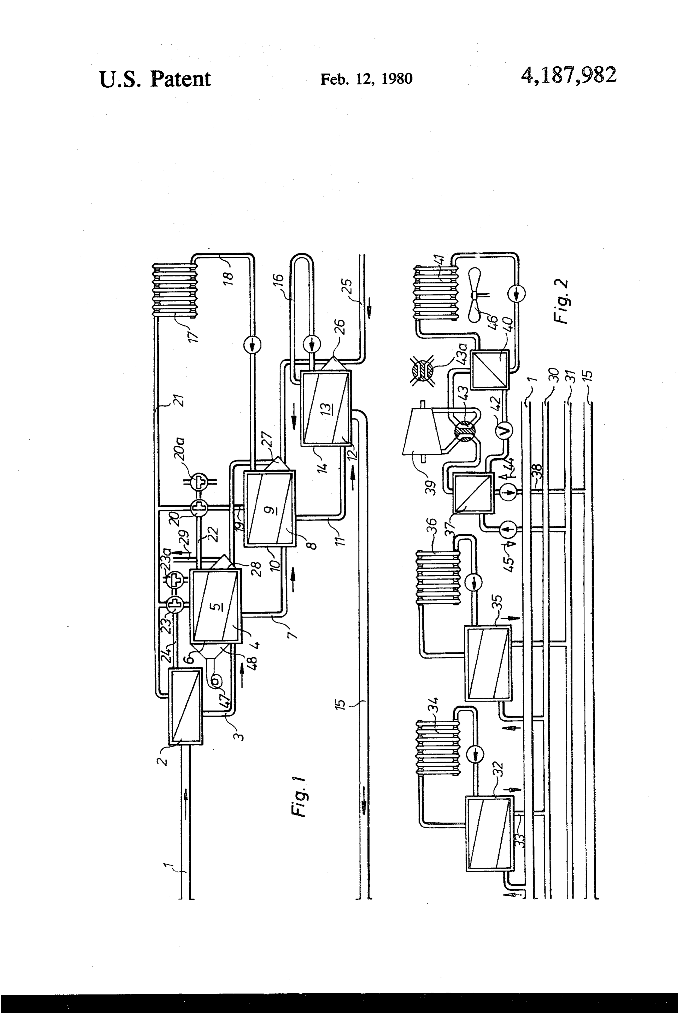
series and arranged for the passage therethrough of a The invention will be described with reference to stream of water from a remote heating grid. Thereby drawings.
they become charged simultaneously and the remote 25 FIG. 1 shows an embodiment of the invention in heating water leaves the building of the heat consumer which the heat carrier of the remote heating input first at a relatively low temperature. By means of this inven flows through the heat exchanger. tion the remote heating conduit comprising part of a FIG. 2 shows a remote heating grid having the input heat supply circuit can be operated continuously over a conduit and the return conduit and two compensating period of 24 hours at its full capacity, so that for any 30 conduits.
given diameter of the pipe conduit of the remote heat FIG. 1 shows an arrangement embodying the inven ing grid, approximately twice the heat quantity previ tion, in which the heat carrier of the remote heating ously transmitted can be transmitted, with a consequent input 1 first flows through the heat exchanger 2. Then it increase in the rating of the remote heating grid. is conducted via the conduit 3 through a heat exchanger The flow in the internal heat user circuit of the build 35 4, with which the storage mass 5 in the storage con ing is in the opposite direction to that of the remote tainer 6 is in good heat-conducting contact. Thereafter heating water stream which charges it. The invention the heat carrier flows through the conduit 7 into the proposes the introduction of heating elements which heat exchanger 8, which is in good heat-conducting cause the heating water to be cooled to a substantial contact with the storage mass 9 of the storage device 10. extent. These include especially counter-current con In the same way it then flows through the conduit 11 vectors as well as large area heating elements; there is and the heat exchanger 12, which is in heat-conducting moreover provided a series circuit of consumers at contact with the storage mass 13 of the storage device differential working temperatures, the arrangement, for 14 and then enters the return conduit 15. Input 1, con example, being such that the flow takes place first duits 3, 7, 11 and return conduit 15 all form part of a through a radiator, then a ceiling heating installation 45 heat supply circuit. The heat storage device 14 having and finally a floor heating installation. The relatively the lowest crystallization temperature supplies the cold return water of the heating circuit of the consumer large-area heating element 16. From the remaining radi is preheated by the latent heat storage device at the ators 17 of the house, the discharge 18 from the radiator lowest temperature and finally flows through the latent is conducted through the heat storage device 10. There heat storage device having the highest crystallization 50 the water is subjected to a first increase in temperature temperature. Moreover it is thereafter yet heated by a and then reaches the three-way valve 20 through the heat exchanger from the remote heating input tempera conduit 19. If by now the temperature of the water is ture to a temperature corresponding to the remote heat adequate for space heating, then the heat carrier again ing temperature. If the maximum heating capacity is not reaches the input 21. If the water temperature is not required in the heating circuit, flow takes place only 55 adequate for the heating demand, then the three-way through the latent heat storage devices of appropriately valve is pivoted to the position shown at 20a. The water low crystallization temperature; i.e. the latent heat stor then reaches the heat storage device 6 via the conduit age devices operating at a higher temperature are not 22, whence it may again selectively by means of the discharged. three-way valve 23, proceed directly into the input The heating of water for consumption also takes 60 conduit 21 or, when the further three-way valve is in place via a plurality of heat exchangers disposed in the the position shown at 23a, it may be conducted via the latent heat storage devices, through which, beginning conduit 24 through the heat exchanger 2 and then enter with the lowest temperature, flow takes place in the the input conduit 21 only when it has reached its maxi opposite direction to that of the remote heating circuit. mun temperature. Discharge 18 and input 21 as well as In accordance with the invention it is possible not 65 conduits 19-24 all form part of a heat user circuit. only to sub-divide the heat storage devices into such In accordance with the invention heat is consumed at devices of differential temperature within a building, any time only at the lowest possible temperature, and but also within a district being supplied. Some of the only on extremely cold days is an input temperature 4 achieved in the conduit 21 owing to the valve positions changer for exchanging heat between said supply cir 20a and 23a, which corresponds approximately to the cuit and said user circuit, a first latent heat storage de temperature of the remote heating conduit 1. vice having a first heat storage mass in heat conducting The heating of the water for consumption also takes contact with said one heat exchanger and where said place by counter-flow through the conduit 25 which first mass experiences a phase change at a temperature leads from the water supply conduit to the heat ex below the temperature of said heat carrier medium changer 26, thence flows through the heat exchanger 27 coming from the remote heat grid whereby heat sup and thereafter the heat exchanger 28, in order finally to plied by said heat carrier medium may charge said heat be supplied via the conduit 29 to the hot water supply storage mass during periods of low withdrawal of heat grid of the consumer. For the purpose of meeting an 10 by said heat user circuit, a second heat exchanger for extreme peak demand, the burner 47 is provided which exchanging heat between said supply circuit and said gives off its heat via the heat exchanger 48 to the heat user circuit and a second latent heat storage device storage device 6 as well as the heat exchanger 4, so that containing a second heat storage mass in heat conduct the heat which is additionally provided by it can also be ing contact with the second heat exchanger and where transmitted to the other heat storage devices. The 15 the second mass has a lower phase change temperature burner 47 may alternatively be provided in the circuit than the first mass and whereby said first heat ex (23-18). changer is positioned upstream of said second heat ex FIG. 2 shows a remote heating grid having the input changer with respect to the direction of flow of said conduit 1 and the return conduit 15 and two compensat heat carrier medium from said remote heating grid. ing conduits 30 and 31 where all of the conduits form 20 2. A heating circuit according to claim 1 wherein said part of a heat supply circuit. Between the input 1 and heat supply circuit includes a return circuit connected the compensating conduit 30 a first group of consumers to an output of the second heat exchanger and which 34 is connected, whose heating systems require a high connects with an input to said heat grid whereby cooled water temperature. The remote heat carrier stream is heat carrier supply medium may be recirculated back to subjected to slight cooling in the latent heat storage 25 said remote heating grid.
device 32 and reaches the compensating conduit 30 3. A heating circuit according to claim 2 wherein said through the return conduit 33. From there the latent heat user circuit includes first conduits connecting the heat storage devices for the consumers 36, operating at downstream sides of said heat exchangers with said a lower temperature, are supplied. From the compensat heating elements and a second conduit connecting the ing conduit 31 water which has by now been cooled to 30 downstream side of a substantial extent reaches such buildings in which a upstream side of thethe second heat exchanger with the first heat exchanger and a valve in heat pump is installed, the evaporator 37 and thence via said conduits for controlling flow of said heat user me the conduit 38 the return conduit 15. The compressor 39 dium sequentially through said heat exchangers to said sucks an expanding working medium from the heat heating elements.
exchanger 40, which acts as a liquifier. The latter 35 4. A heating circuit according to claim 1 wherein said supplies the heating circuit 41. Via the throttle valve 42 the working medium condensate again reaches the heat grid comprises an input, a first compensating conduit, a exchanger 37. By switching over the fourway valve 43 second compensating conduit, a return conduit and into the position 43a the same heat pump acts as a refrig wherein said first heat storage device is connected be eration machine. It withdraws cold water from the 40 tween said input and said first compensating circuit and return conduit in the direction of the arrow 44, heats it said second heat storage device is connected between and conducts it into the compensating conduit 31 in the the first compensating conduit and a conduit selected direction of the arrow 45. The fan 46 attends to the from a group comprising said second compensating convective heat exchange. conduit and said return conduit. We claim: 45 5. A heating circuit according to claim 4 having in 1. A heating circuit including a heat supply circuit of addition a heat pump comprising an evaporator con a predetermined transmission capacity adapted to be nected in said return conduit.
supplied with a heat carrier supply medium from a 6. A heating circuit according to claim 5 having in remote heating grid, a heat user circuit containing a addition a switch means interposed in the heat user heat carrier user medium for withdrawing heat from 50 circuit whereby waste heat from said heat pump may be said heat supply circuit including a plurality of heating imposed on heat carrier supply medium withdrawn elements where the transmission capacity of the user from said return conduit and imposed on a compensat circuit is greater than said predetermined transmission ing circuit. sk k sk ck ck capacity of the supply circuit, at least one heat ex
Provenance
- Collection
- Patents citing this work
- Pages
- 4
- Method
- pdftotext (the PDF's own text layer) + pdftoppm 300dpi page scans
- Patent office record
- patents.google.com →
- Source
- Google Patents citing-documents table
- Assignee
- Ingeborg Laing
- Published
- 1980-02-12
- Transcribed from
- patentimages.storage.googleapis.com →