

patent · US4325359A
Focusing solar heat collector
20 April 1982
Text
Page 1bibliographic recordscan →
United States Patent (19)
Fries
FOCUSING SOLAR HEAT COLLECTOR
Inventor: James E. Fries, 7860 Valley View
St., Apt. 242, Buena Park, Calif.
Int. Cl.................................................. F24J 3/02 (52) U.S. Cl. .................................... 126/438; 126/417;
1,258,405 3/1918 Harrison ............................. 126/438
3,939,819 2/1976 Minardi ........................... 126/900 X 3,986,491 10/1976 O’Hanlon ............................ 126/440
4,106,952 8/1978 Kravitz ............................... 126/440
Primary Examiner-Larry Jones
Attorney, Agent, or Firm-Lyon & Lyon
A focusing solar heat collector comprises a light reflec tive corrugated base surface, a plurality of spaced apart, light-transmitting conduits positioned in the corruga tions of the reflective surface so that light reflected by the reflective surface is focused on the conduits, and an organic black liquid of high boiling point circulated through the conduits to receive the focused solar light. 5 Claims, 3 Drawing Figures
Drawings
Page 2drawing sheetscan →
Page 3scan →
heat loss on windy days. An organic black liquid having
FOCUSING SOLAR HEAT COLLECTOR a high boiling point, preferably having a boiling point in excess of that of water, and of at least 300 F., is circu
BACKGROUND OF THE INVENTION lated within the conduits to absorb solar radiation. The present invention relates generally to solar heat When the organic black liquid is motor oil, the focusing collectors. More specifically this invention relates to a solar heat collector does not freeze at very low outside focusing solar heat collector. temperatures, i.e. below 0. F., and does not boil when Due to ever increasing usage of non-renewable en exposed to very high outside temperatures, i.e. higher ergy sources such as fossil fuels, much attention is being than 110 F.
directed toward solar energy. Solar energy has been 10 The focusing solar heat collector is oriented opti found to be effective in providing space and water heat mally to receive solar energy on a roof or other place. 1ng. The solar heated black liquid is circulated through a Many solar heat collectors are attractive in perfor heat exchanger to effect space heating or heating of mance but lack in cost-effectiveness. Many solar heating water for bathing, swimming, or operation of certain systems require several years of operation to return the heat engines.
initial investment, turning many citizens away from solar energy as an alternative energy source. Therefore, DRAWINGS there is a need for a simple, efficient, and most impor These and other features, aspects, and advantages of tantly, an inexpensive solar heat collector. the present invention will become better understood Solar heat collectors are generally divided into two 20 with reference to the following description, appended catagories depending on how they function to utilize claims, and accompanying drawings where: the sunlight.
One category of solar heat collectors utilizes the collector1 according
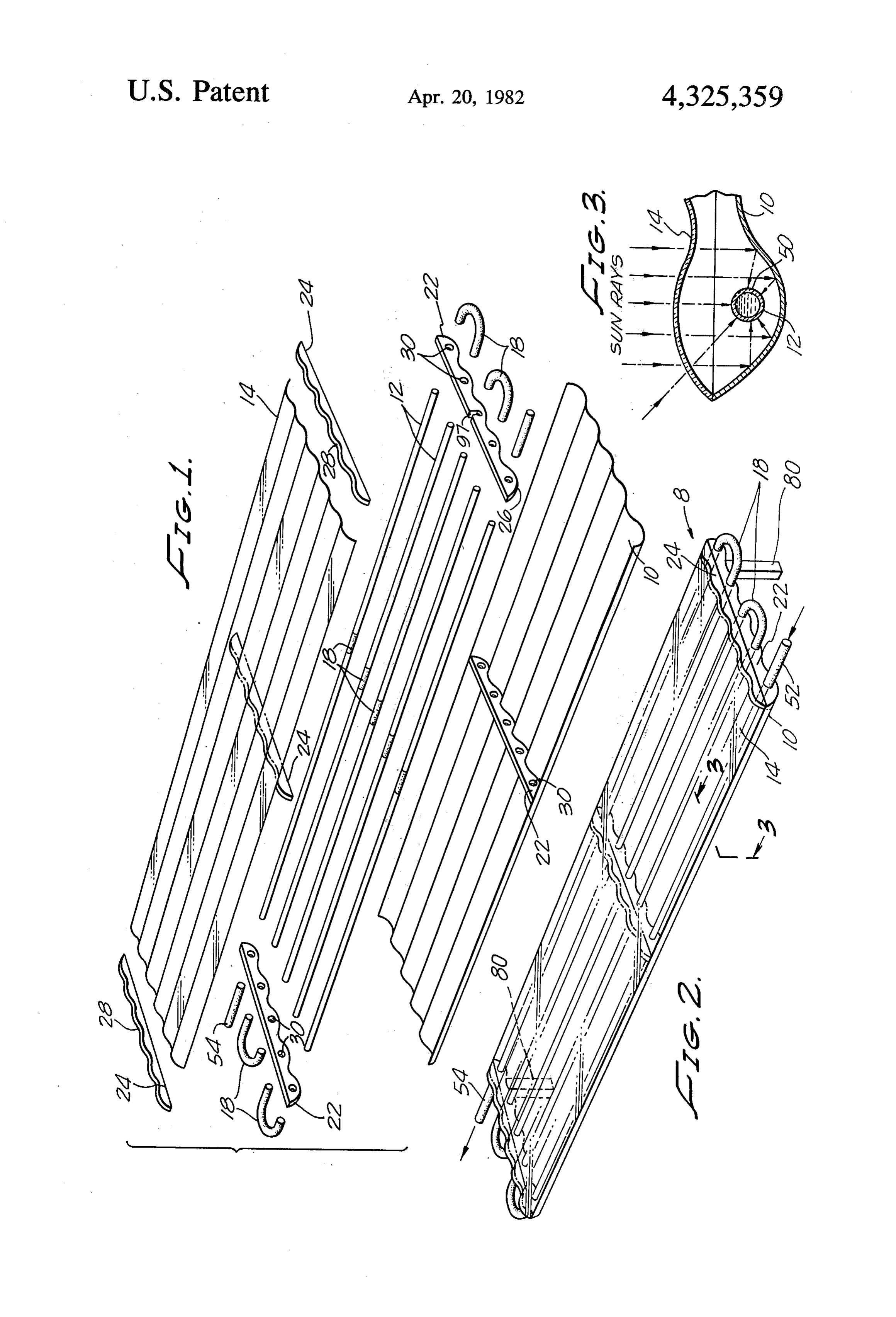
FIG. is an exploded view of a focusing solar heat to the present invention;
device of the "green-house effect'. Usually they oper ate in a stationary position, taking advantage of light- 25 collector of FIG. 1 after view FIG. 2 is a perspective of the focusing solar heat assembly; and transmitting covers which trap heat energy of longer FIG. 3 is a cross-sectional view of the focusing solar wavelengths produced by penetrating shorter wave lengths of light which are absorbed by black surfaces heat collector of FIG. 2 taken along line 3-3 in FIG. 2. situated beneath the covers. In U.S. Pat. No. 3,194,228 DESCRIPTION to Bargues, a black corrugated panel with conduits 30 With reference to the figures, a focusing solar heat attached is used to absorb solar radiation. Water is cir culated through the conduits to collect the heat. An collector prises a 8 according to the present invention com light reflective corrugated base surface 10, a other "green-house effect” type of collector is de plurality of spaced apart, light-transmitting conduits 12, scribed in U.S. Pat. No. 4,055,163 to Costello et al. This collector differs from the Bargues collector in that a 35 and a light-transmitting upper surface 14 which is air black liquid is utilized in lieu of a black corrugated panel spaced over the conduits 12. The conduits 12 are posi to absorb solar radiation. This collector employs a non tioned in correspondingly spaced apart corrugations of focusing reflective surface to remove unwanted heat. the reflective surface 10 so that light reflected by the The black fluid is circulated through a light-transmit reflective surface is focused on the conduits. ting conduit which is situated above the reflective sur- 40 The light reflective corrugated surface can be formed face substantially masking the reflective surface from of metal, metallized plastic, plastic coated with alumi sunlight when in operation. The heated black liquid is num foil, or the like. It is important that the surface 10 circulated through a heat exchanger which transfers reflects a substantial proportion of the light that im heat to water. pinges upon it. The valleys of the corrugations may be Related to the present invention are focusing type 45 parabolic in curvature. Also, the corrugations of the solar heat collectors. Focusing type solar heat collec corrugated surfaces are sufficiently large with respect tors, which represent the second category of solar heat to the conduits 12 such that the conduits do not substan collectors, obtain high efficiency by concentrating sun tially mask the reflective surface 10 which focuses sun light by means of reflectors or lenses. A large area of light upon the conduits 12. Preferably, the conduits 12 sunlight is focused onto a smaller target or conduit. A 50 can fit within the corrugation valleys without contact liquid such as water is circulated through the target or ing the light reflective surface. conduit to collect heat by conduction. In U.S. Pat. No. The conduits are substantially transparent, and of 2,907,318 to Awot, a corrugated reflected surface is necessity, transmit a substantial amount of light. The employed as means for focusing sunlight onto conduits conduits can be formed by a single tube placed in ser positioned in the valleys of the corrugations. This col- 55 pentine fashion within the corrugation. Alternatively, lector employs a light-transmitting cover air spaced as shown in the drawings, a plurality of separate tubes over the conduits. 12 interconnected by connectors 18 such as neoprene rubber connectors or teflon connectors can be used.
Summary of the invention
The conduits can be formed of a suitable transparent
The present invention is directed to a focusing solar 60 plastic, or a suitable glass, or the like. Preferably, the heat collector. The collector comprises a light reflec material used for the conduits should not be chemically tive corrugated base surface, and a plurality of spaced degraded or dissolved by the fluid circulated in the apart, light-transmitting conduits positioned in corre conduits.
spondingly spaced apart corrugations of the reflective Preferably, the conduits are maintained spaced apart surface so light reflected by the reflective surface is 65 from the corrugated surface 10; the air space acts as an focused on the conduits. A light-transmitting upper insulator because air is a relatively poor conductor of surface is air spaced over the conduits to protect the heat. Also, if the collector is not optimally oriented to reflective surface from weathering and help prevent receive solar light energy, more light rays can be re 4 flected onto the conduits than if a portion of the reflec building, or suitable heat engines which can operate in tive surface is directly masked (i.e. in contact) with the this temperature range.
conduit. At this point, it may be noted that the bottom As shown in FIG. 3, sun rays can pass through the of the base surface 10 can be layered with insulating transparent upper cover 14, and impinge directly onto material if desired. the black fluid 50 or be reflected thereto from the reflec The upper surface 14 is made of a light-transmitting tive surface 10.
material such as glass; or rigid or flexible plastics such as The focusing solar heat collector can be mounted on acrylic, Tedlar (E), and polycarbonate; or the like. One a roof or other place exposed optimally to direct sun or more layers of transparent or nearly transparent light. The collector is mounted to orient the conduits materials can be used for the upper surface cover 14. It 10 horizontally lengthwise in an east-west alignment. Ad is not necessary that the upper surface be rigid and ditionally, the collector is tilted on a north-south axis by corrugated, but it is preferable. The corrugations of the means of props 80 or supporting tilting frame such that upper surface in combination with the lower surface 10 sunlight is optimally focused upon the conduits. A provide a pleasing aesthetic effect. In addition, a corru weekly tilting is adequate. More precise focusing could gated upper surface 14 imparts added strength and ri 5 be achieved by a daily adjustment.
gidity to the collector and allows rain water drainage. In a preferred version of the present invention, the The upper transparent surface 14 helps protect the reflective surface 10 is a rectangular 26'X8' reflective lower reflective surface 10 from effects of weather aluminum corrugated panel, having 10 corrugations. which could decrease the reflectivity of the lower sur The conduits are made of transparent heat-shock resis face 10. 20 tant glass tubing of inch outer diameter which is com As shown in the drawings, the conduits 12 are air mercially available under the trademark Pyrex (E) or spaced apart from both the reflective base surface 10 under the trademark Kimax (R). Each piece of tube is 4' and the upper surface 14. It is desirable to space the long and each row consists of 2 tubes. The individual conduits away from both upper surface 14 and lower sections of tubing are connected with neoprene rubber surface 10 to help avoid conductive heat losses through 25 connectors 18 having a inch inner diameter and 3 inch these surfaces. This spacing can be effected with end outer diameter. The entrance connector 52 and dis and middle spacers in the solar collector. As best shown charge connector 54 are likewise neoprene. in FIG. 1, at each end of the solar heat collector and in Teflon (R) tubing and flexible connectors can also be the middle there are located a bottom spacer 22 and an used in lieu of neoprene rubber. Also, the collector can upper spacer 24. The bottom spacers have a scalloped 30 be modified to accommodate glass or plastic tubing bottom surface 26 to match the corrugations of the which has been performed into a serpentine or manifold reflective surface 10. Likewise, the top surface 28 of shape. This can be achieved by cutting a slot 97 above each upper spacer 24 is scalloped to match the corruga all mounting holes 30 to receive the rigid glass or plastic tions of the upper surface 14. The bottom spacers 22 configuration.
have mounting holes 30 through which the conduits 12 35 The focusing solar heat collector of the present in are supported. vention is inexpensive to fabricate, an operative em An important feature of the present invention is the bodiment of the invention costs less than $15 to manu working fluid 50 circulated within the conduits 12. The facture. Moreover, the present invention is sturdy and working fluid is an organic liquid having a high boiling light-weight, and achieves a high temperature. High point, appreciably above that of aqueous liquids. Prefer 40 heats can be obtained using this focusing arrangement ably, this liquid has a boiling point temperature of at using a black working fluid of a high boiling point. It is least about 300 F. This allows the working fluid 50 to aesthetically pleasing, and the black fluid does not cor be used at a greater range of temperatures than aqueous rode the conduits, pumps, or heat exchangers. Further liquids. Unlike conventional solar heaters where water more, it can be used in winter without the addition of is used as the working fluid, the solar heater of the 45 antifreeze required with solar heat collectors using present invention can withstand even subfreezing tem water as the main constituent of the working fluid. Very peratures without need for addition of antifreeze chemi hot days or pump breakdowns could boil water in con cals. The use of a high boiling point liquid also lessens ventional solar heat collectors; pressure problems with the need for pressure relief devices which are a neces water systems could damage a solar heating system. sary fixture in aqueous systems which have a lower 50 Another advantage of the collector is that it is not boiling point. Another feature of the working fluid is mandatory that the conduits be within an air tight con that it is black. Preferably, the fluid used is motor oil tainer as required with other solar heaters. Because of containing carbon, preferably in the form of graphite. the advantages obtained through the focusing arrange Oil does not damage or corrode metal pumps or metal ment of the present invention along with the use of an heat exchangers, another advantage. Such a fluid is a 55 efficient black liquid heat absorber, the loss in efficiency commercially available motor oil sold under the trade resulting from a non-sealed enclosure is more than over mark of Arco Graphite Motor Oil (R). This is a multi COC.
viscosity oil, which permits it to be used at very low Although the present invention has been described in temperatures and very high temperatures. It is an excel considerable detail with reference to certain preferred lent solar heat absorber and can be pumped through the versions thereof, other versions are possible. For exam conduits. ple, instead of connecting the conduits 12 in series as In use, the organic black liquid 50 is pumped into the shown in the drawings, they can be connected in paral conduits 12 via an entrance 52, passes through all the lel using manifolds to minimize pressure drop through conduits, and is discharged at the opposite corner 54 of the focusing solar heat collector. Therefore, the scope the solar heater. 65 of the appended claims should not necessarily be limited The solar heated fluid is circulated through commer to the description of the preferred version contained cially available heat exchangers to effect heating of herein.
domestic hot water, swimming pools, space heating of a What is claimed is:
Page 5scan →
1. A focusing solar heater collector comprising: corrugations of the reflective surface so that light (a) a light reflective corrugated base surface; reflected by the reflective surface is focused on the (b) a plurality of spaced-apart, light-transmitting con conduits, the conduits not substantially masking the duits positioned in correspondingly spaced-apart light reflective corrugated base surface from sun corrugations of the reflective surface so that light light;
reflected by the reflective surface is focused on the (c) a light-transmitting upper surface air spaced apart conduits, the conduits not substantially masking the from the conduit;
light reflective corrugated base surface from sun (d) an organic black liquid having a boiling point of at light; least 300' F. within the conduits to receive the (c) a light-transmitting upper surface air spaced apart 10 focused light;
from the conduit; (e) means for tilting the base surface, conduits, and (d) a black liquid within the conduits to receive the upper surface together to focus sunlight upon the focused light; conduits; and (e) means for tilting the base surface, conduits, and (f) means for supporting at least a portion of the con upper surface together to focus sunlight upon the 15 duits air-spaced apart from the reflective surface. conduits; and 3. The collector of claim 1 or 2 in which the liquid is (f) means for supporting at least a portion of the con oil.
duits air spaced apart from the reflective surface. 4. The collector of claim 3 in which the oil contains 2. A focusing solar heater collector comprising: graphite.
(a) a light-reflective corrugated base surface; 20 5. The collector of claim 1 or 2 in which the light (b) a plurality of spaced-apart, light-transmitting con transmitting surface is corrugated. duits positioned in correspondingly spaced-apart k k is k
Provenance
- Collection
- Patents citing this work
- Pages
- 5
- Method
- pdftotext (the PDF's own text layer) + pdftoppm 300dpi page scans
- Patent office record
- patents.google.com →
- Source
- Google Patents citing-documents table
- Assignee
- Fries James E
- Published
- 1982-04-20
- Transcribed from
- patentimages.storage.googleapis.com →